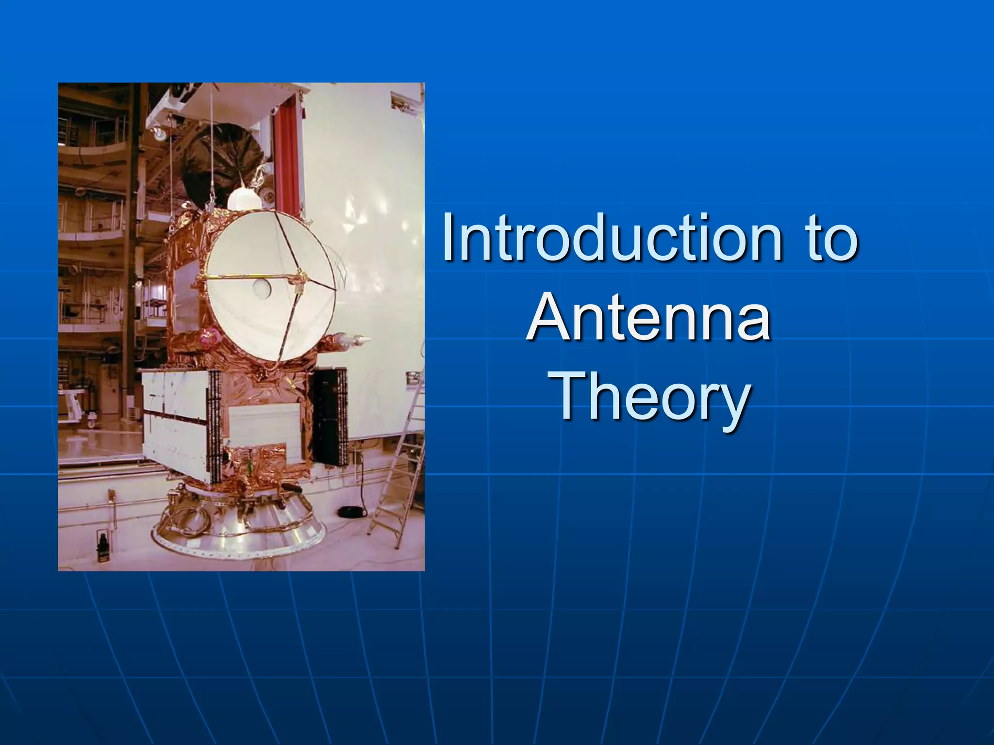
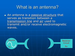
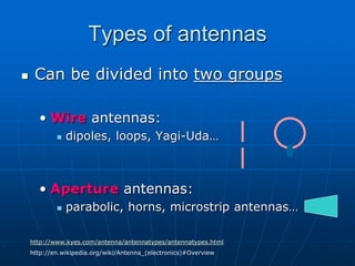
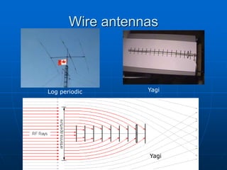
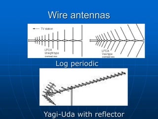
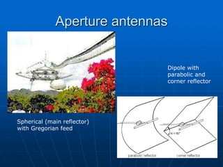
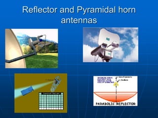
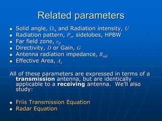
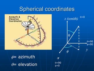
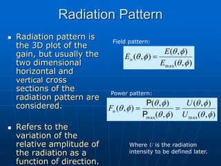
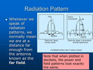
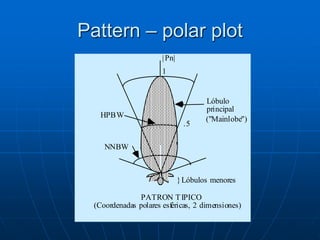
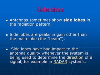
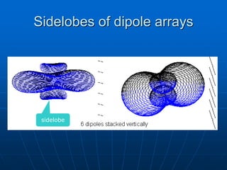
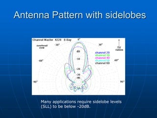
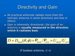
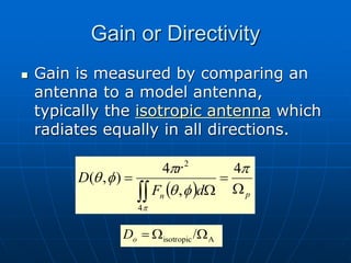
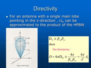
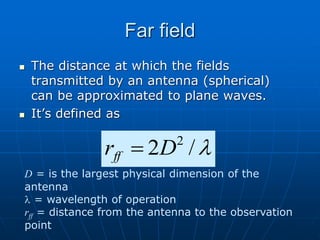
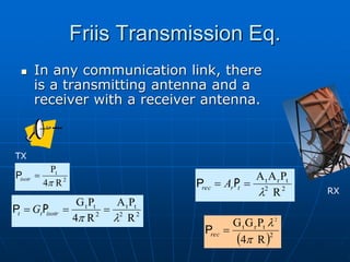
An antenna is a structure used to transmit and receive electromagnetic waves between a transmission line and the air. There are two main types of antennas: wire antennas such as dipoles and loop antennas, and aperture antennas such as parabolic and horn antennas. Key antenna parameters include radiation pattern, directivity, gain, beamwidth, impedance, polarization, and effective area. Antenna performance can be analyzed using concepts such as solid angle, radiation intensity, and the Friis transmission equation. Antenna arrays use multiple antennas to shape the radiation pattern and increase gain through pattern multiplication.

![Solid Angle
s1 = r dq s2 = r sin q dø
s = qr = arc dA = s1 s2
dA = r2 sin q dø dq
= r2 dΩ
q = Plan angle dΩ = Element of solid angle
•The arc of a complete cirlce: • Area of a complete sphere:
= 2pr = 4pr2
•Total angle: = 2p [radianes] •Total solid angle: =4p [rad2]
=4p [sr]
1 steradian (sr) = (1 radian)2](https://image.slidesharecdn.com/fdocuments-220801043430-16d88cc6/85/fdocuments-net_introduction-to-antenna-theory-ppt-11-320.jpg)
![Radiation Intensity
Is the power density per solid angle:
vector.
Poynting
as
known
also
density
power
the
is
]
[W/m
ˆ
Re 2
r
2
r
H*}
{E
½
where
r
U
r
P
P [W/sr]](https://image.slidesharecdn.com/fdocuments-220801043430-16d88cc6/85/fdocuments-net_introduction-to-antenna-theory-ppt-12-320.jpg)
![Total radiated power by antenna
Can be calculated as;
[W]
[W]
W
dS
P
or
d
U
P
r
rad
rad
P](https://image.slidesharecdn.com/fdocuments-220801043430-16d88cc6/85/fdocuments-net_introduction-to-antenna-theory-ppt-13-320.jpg)
![Total Solid Angle of an antenna
z
y
x
žA
Patrón
|P |
n
[sr]
)
,
(
4
A W
W d
Fn
p
f
q WA
Is as if you changed the
radiation pattern
beam of an antenna
into a pencil beam
shape and find out
what’s the equivalent
solid angle occupied by
this pattern.](https://image.slidesharecdn.com/fdocuments-220801043430-16d88cc6/85/fdocuments-net_introduction-to-antenna-theory-ppt-15-320.jpg)
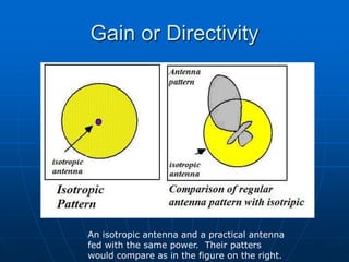
![Isotropic antenna
It’s an hypothetic antenna,
i.e., it does not exist in real
life, yet it’s used as a
measuring bar for real
antenna characteristics.
It’s a point source that
occupies a negligible space.
Has no directional
preference.
Its pattern is simply a sphere
so it has WA= Wisotropic= 4p
[steradians].
p
f
q
q
p
q
p
f
p
4
sin
)
1
(
)
1
(
0
2
0
4
isotropic
W
W
d
d
d](https://image.slidesharecdn.com/fdocuments-220801043430-16d88cc6/85/fdocuments-net_introduction-to-antenna-theory-ppt-16-320.jpg)

![Radar equation
What is a radar?
Received power by a radar from a single
target is
Where s is the backscattering coefficient of
the target [m2]
s
p
2
4
3
2
2
4
e
R
G
P
P o
o
t
r](https://image.slidesharecdn.com/fdocuments-220801043430-16d88cc6/85/fdocuments-net_introduction-to-antenna-theory-ppt-32-320.jpg)
![Antenna Arrays
Uses many antennas synchronized
with each other to increase
Pattern multiplication, AF
[ ]
Factor
Array
Pattern
Antenna
Individual
)
(
r
E
2
sin
2
sin
N
N
AFN
1
-1 1
x
|T (x)|
4
-R
x
0
°
Uniform illumination Tschebyscheff Illumination](https://image.slidesharecdn.com/fdocuments-220801043430-16d88cc6/85/fdocuments-net_introduction-to-antenna-theory-ppt-39-320.jpg)