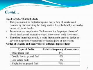
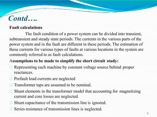
1) The document discusses fault analysis and short circuit studies, which are important for designing protective schemes for power systems. It defines different types of faults like symmetrical, shunt, series, and explains their characteristics.
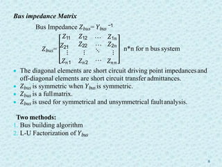
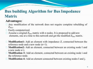
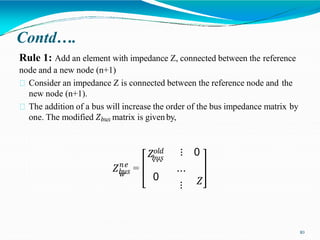
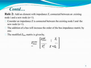
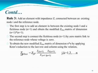
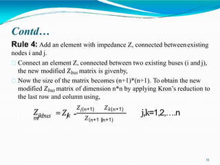
2) Bus impedance matrix calculation methods like bus building algorithm are explained. The algorithm allows modification of the matrix when network changes without complete rebuilding.
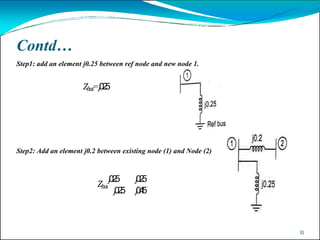
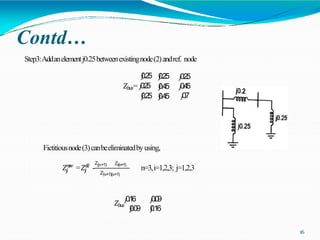
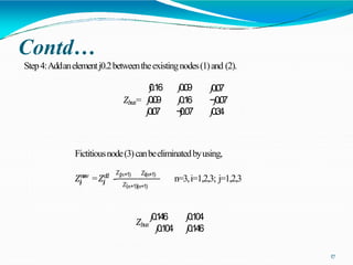
3) An example demonstrates using the bus building algorithm to determine the bus impedance matrix for a sample network. Assumptions and applications of short circuit studies in protection are also summarized.