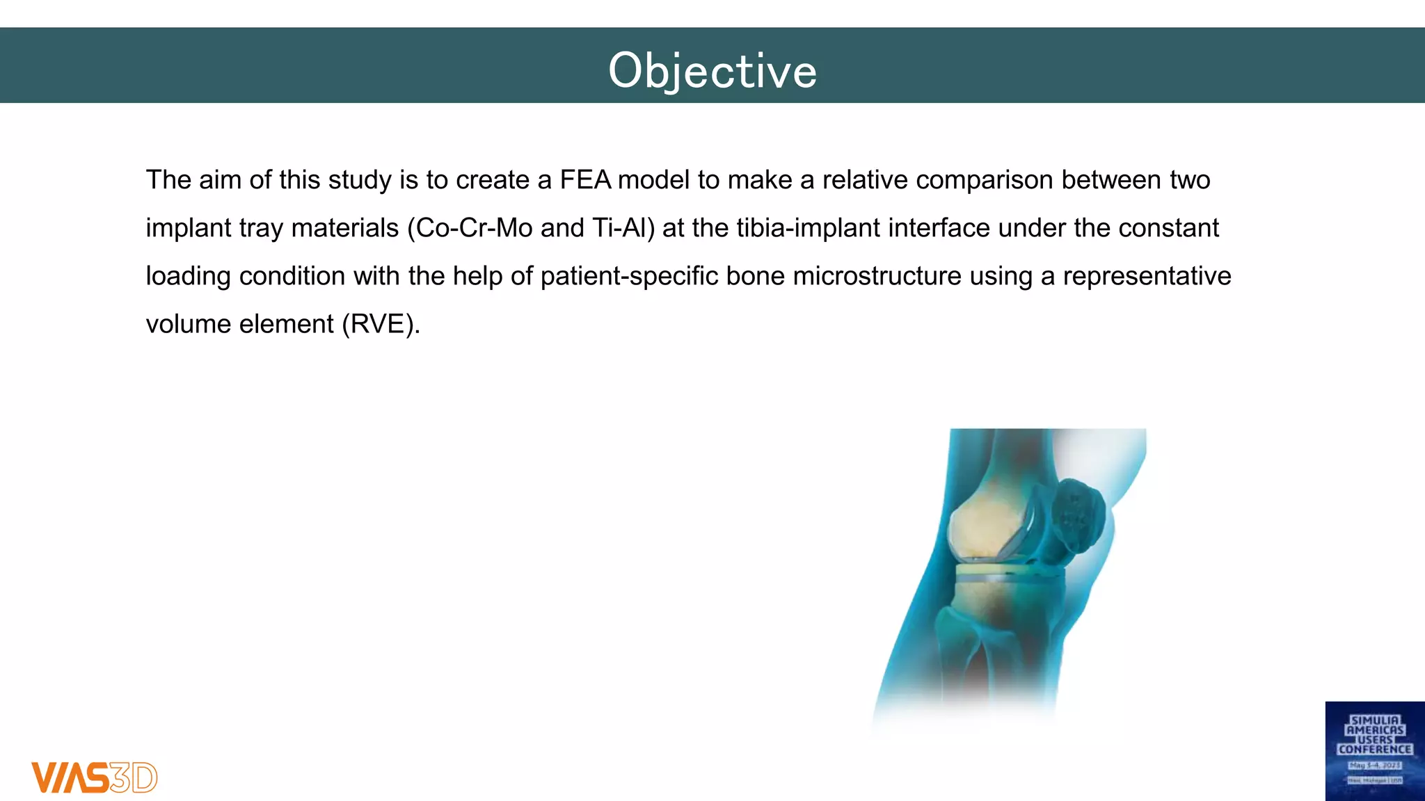
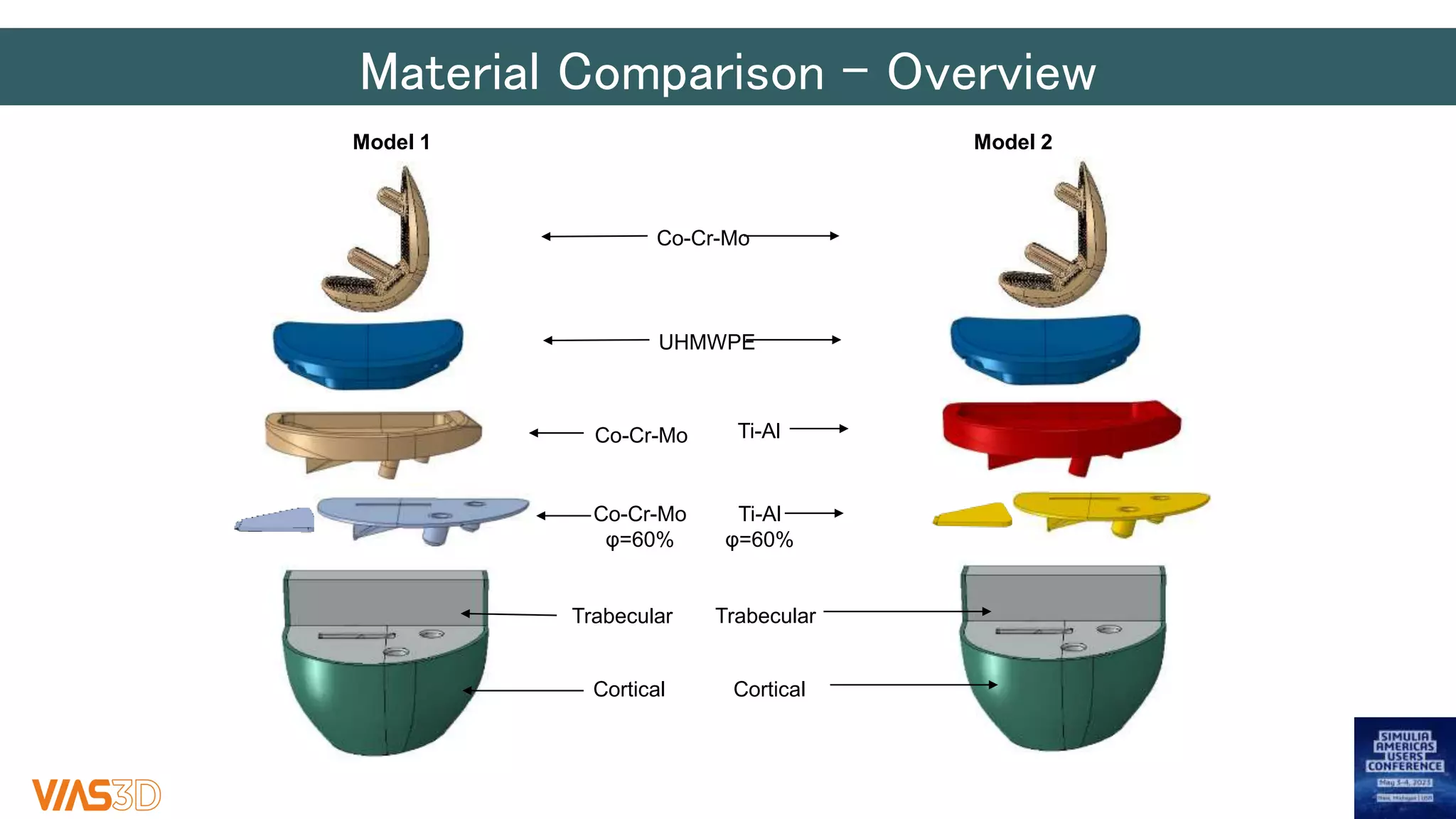
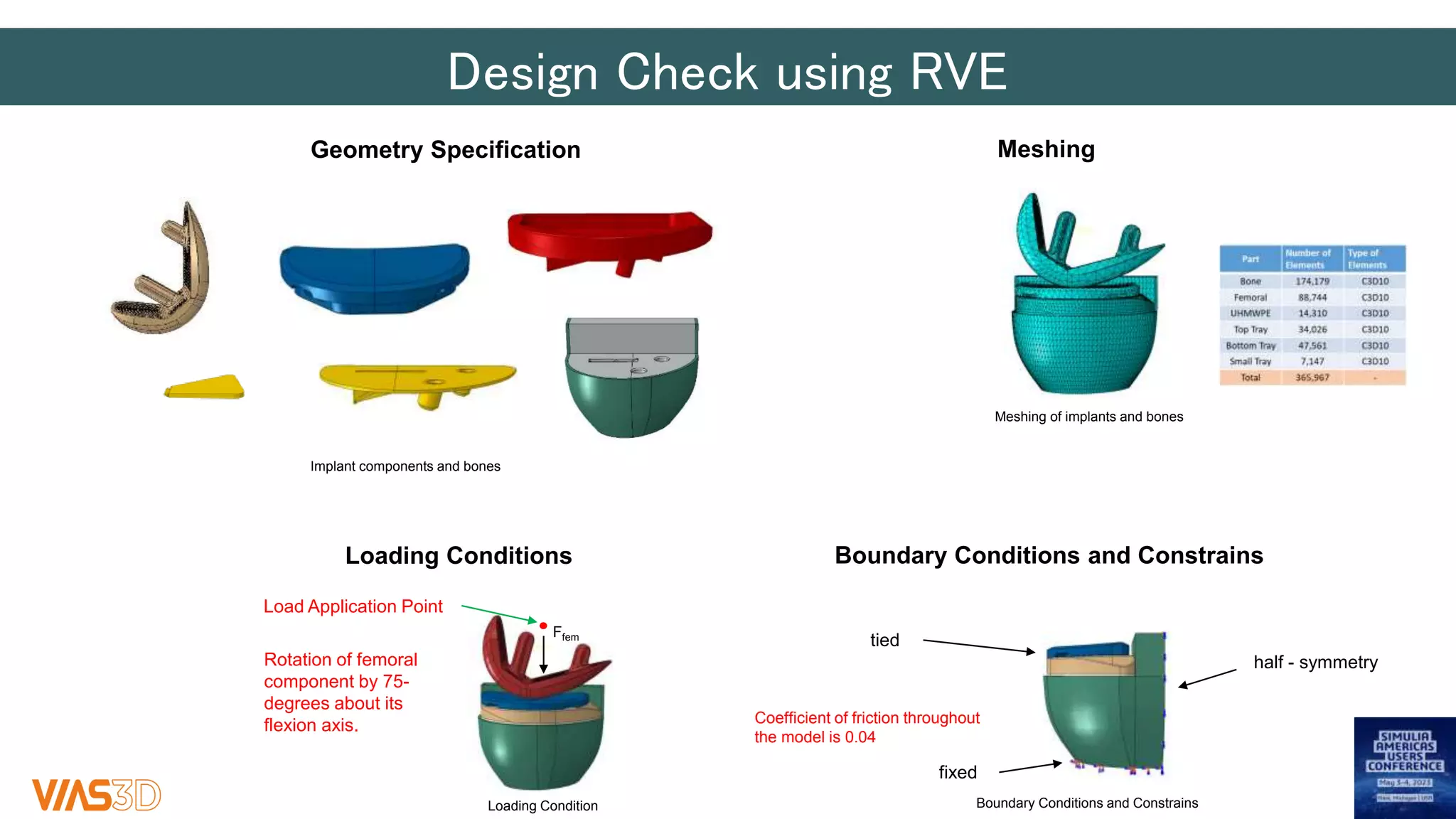
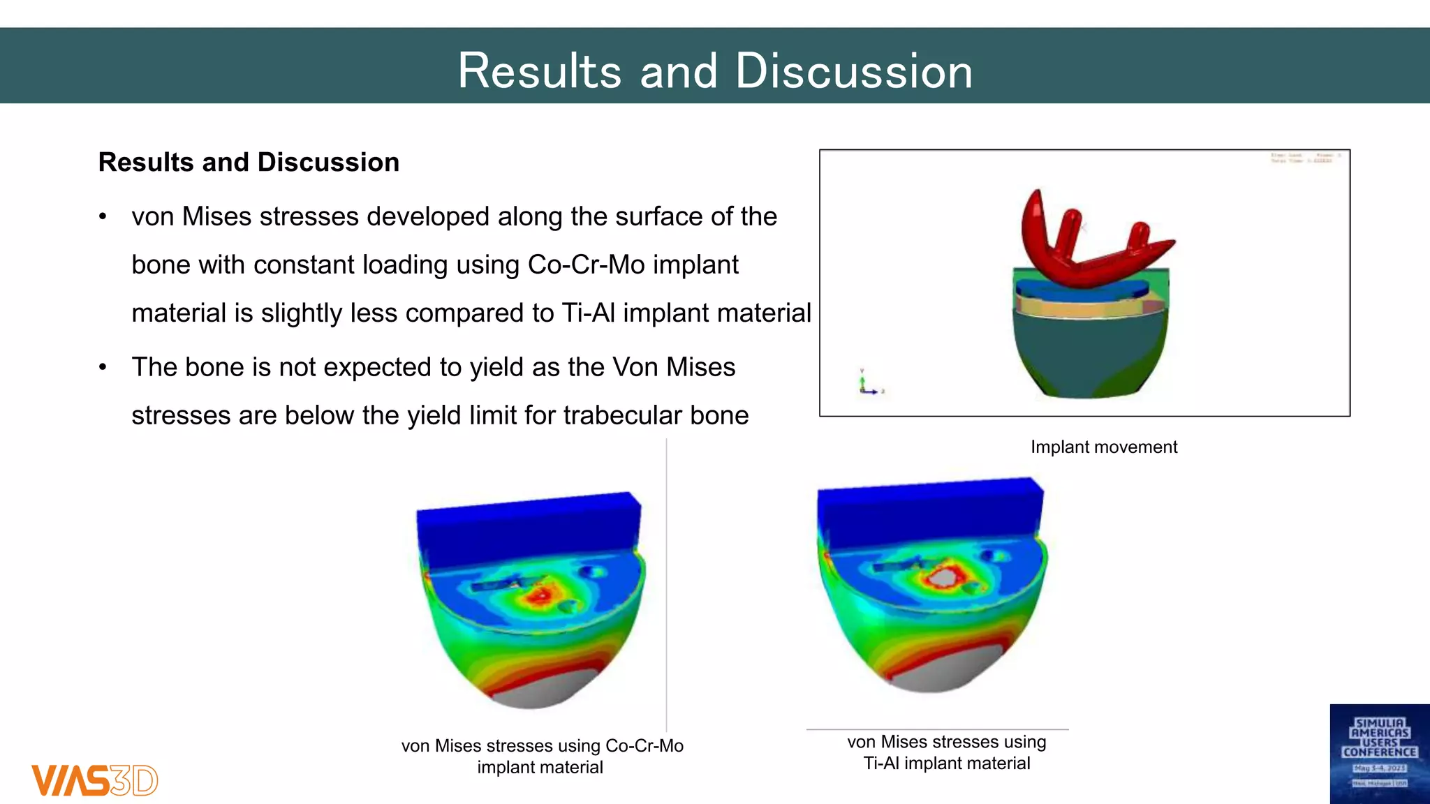
Engineered to Cure – Patient
Specific Tibial Implant Design using
Micro-Macro FEA Framework
www.VIAS3D.com
USA Canada India Mexico
May 2023
Dr. Arindam Chakraborty, CTO – Consulting Services
achakraborty@vias3d.com
Dr. Srikanth Srigiriraju​, Lead Consultant – Consulting Services​
ssrigiriraju@vias3d.com
Georgiy Makedonov, Simulation Engineer – Consulting Services
gmakedonov@vias3d.com
VIAS3D Introduction
2
Who We Are
Engineering
Consultancy
Training
& Staff
Aug.
Automation &
Customization
Software
• Multiple Industry Experience – Medical Devices, CPG, Appliances, Hi-
tech, Automotive, Oil & Gas, Petrochemical & Process, Aerospace, Industrial
Equipment, and Manufacturing
• Global Presence with Head Office in Houston, TX
• Global team of +200 professionals with Engineering Consulting team consisting
of +40 professional with more than 18 PhDs and MSc/MTechs with expertise in
Design & Manufacturing, Structural & Solid Mechanics, Fluid Mechanics,
Electromagnetics, Optimization & Reliability, Data Analytics, System
Architecture​, Bioscience and Materials, Automation, ..
• Dassault Systèmes Platinum Partner – Global Presence
• Provide Engineering consulting & technical resource augmentation, PLM
implementation, Training, Software Sales and Support, Automation and
Customization
3
Simulation Capabilities
Design by Analysis
FEA based Fracture /
Damage Mechanics /
ECA
Composites and
Elastomer Modelling
Optimization and
Reliability
Simulation Automation
Design
Pressure Drop and Fluid
Flow Regimes
Aero Acoustic Source
Modeling
Material Testing, Corrosion
Testing, Root Cause
Analysis
Fluid Structure Interaction
Electromechanical
Devices/Magnet Design
RF/Microwave Heating
5
Client Engagement Overview
Software Sales and Support
o Proof-of Concept
o Best Practices
o Installation & Post-sales Technical
Support
Support to perform MODSIM
work
o R&D+I
o Technical deep dive in nature
of problem
o Regular projects
o Overflow work
o Urgent needs
o Dedicated Support / On-site /
FTE
Democratization
o 3DX Workflow Development
o Best practices + data management
on 3DX
o Automation (GUI) and templatization
o Web App Solutions
Development of iterative processes
o Optimization
o Material calibration
Training and Knowledge-Transfer
o Standard Training - Basic and Advanced
o Industry Customized
o Project-based – Execute, Train, Hand-
over and Quality watch
6
Engineered to Cure – Patient Specific Tibial Implant Design
using Micro-Macro FEA Framework
Introduction
Background
• Using simulation for knee implant design study
• The use of patient specific-specific bone geometry via µCT
• Digital evidence in the form of virtual patients can be used
• Full digital access to all relevant information enabling to make rapid, science-based, informed
decisions.
Challenges:
• Characterization of physical and mechanical properties of multiphase materials like cancellous and
cortical bones
• Modeling efficiency and accuracy
Objective
The aim of this study is to create a FEA model to make a relative comparison between two
implant tray materials (Co-Cr-Mo and Ti-Al) at the tibia-implant interface under the constant
loading condition with the help of patient-specific bone microstructure using a representative
volume element (RVE).
Implant Selection
• Based on the bone geometry, the implant size was selected, which is slightly smaller than
the cut.
Bone Test Data
Bone Geometry
• The patient-specific bone geometry represented through a cubic volume is
reconstructed using images from a μCT scan.
• The resulting μCT image is converted to grayscale ranging from
0 (black/void) to 255 (white/bone) with the appropriately chosen cut-off
range for further analysis.
• Based on literature, the threshold 70-255 is chosen to segment out the
bone structure.
• Only the specific region of the patient-specific bone sample is used for the
FEA simulation to reduce the memory and computational time of the
analysis.​
70-255
grayscale
(selected)
95.6% bone volume
µCT scan of bone
75-255
grayscale
Selected for FEA
90.1% bone volume
Wu Y, Adeeb S, Doschak MR. Using Micro-CT Derived Bone Microarchitecture to Analyze Bone Stiffness - A Case Study on Osteoporosis Rat Bone.
Front Endocrinol (Lausanne). 2015 May 20;6:80. doi: 10.3389/fendo.2015.00080. PMID: 26042089; PMCID: PMC4438594.
Representative Volume Element (RVE)
RVE Methodology
• The RVE is designed to capture effective structural and material
properties at microscale level which are used as input parameters for
the macroscale.
• The RVE approach performs statistical averaging of
the microstructural features within the given cubic volume by applying
loading from six independent directions (Micromechanics Plugin).
RVE Sample
Bone
Air
Domain Size
Part Properties
Material Properties
Representative Volume Element (RVE) Cont.
RVE Size Selection (Trabecular and Cortical Bones)
• To save processing memory and computational time, an iterative process of determining the RVE cube
size is done such that the porosity in the cube between two consecutive sizes of cubes is not very
different.
• Several sizes of cubic samples are selected along the ML (Mediolateral) and AP (Anteroposterior)
directions of trabecular bone and are compared for porosity.
Cortical Bone Trabecular Bone
Locations of samples selected
(RVE size 1x1x1mm)
Locations of samples selected
(RVE size 5x5x5mm)
5 x 5 x 5 mm
4 samples
~96.2% bone volume average
1 x 1 x 1 mm
3 samples
~98.9% bone volume average
Treece, G M et al. “High resolution cortical bone thickness measurement from clinical CT data.” Medical image analysis vol. 14,3 (2010): 276-90.
doi:10.1016/j.media.2010.01.003
Material Comparison – Overview​
Model 2
Model 1
Co-Cr-Mo
UHMWPE
Co-Cr-Mo Ti-Al
Co-Cr-Mo
φ=60%
Ti-Al
φ=60%
Trabecular
Trabecular
Cortical Cortical
Design Check using RVE​
Geometry Specification
Implant components and bones
Meshing of implants and bones
Meshing
half - symmetry
fixed
Load Application Point
Ffem
tied
Boundary Conditions and Constrains
Loading Conditions
Loading Condition Boundary Conditions and Constrains
Rotation of femoral
component by 75-
degrees about its
flexion axis. Coefficient of friction throughout
the model is 0.04
Results and Discussion
• von Mises stresses developed along the surface of the
bone with constant loading using Co-Cr-Mo implant
material is slightly less compared to Ti-Al implant material
• The bone is not expected to yield as the Von Mises
stresses are below the yield limit for trabecular bone
von Mises stresses using Co-Cr-Mo
implant material
von Mises stresses using
Ti-Al implant material
Implant movement
Conclusions
Conclusions:
• Was able to accurately evaluate designs under different conditions leading to more tailored,
patient-specific implants.
• Using numerical modeling, it was possible to improve product performance by comparing various
design options.
• Reduced number of material testing and lead time reduction.
Future Work
Future Work
• Additional failure criteria (cyclic loading, progressive damage, cracking, etc.)
• End-to-end automated solution – Workflow integrating CAD-Bone CT-FEA
Thank You
www.VIAS3D.com
USA Canada India Mexico

Engineered to Cure – Patient Specific Tibial Implant Design using Micro-Macro FEA Framework

  • 1.
    Engineered to Cure– Patient Specific Tibial Implant Design using Micro-Macro FEA Framework www.VIAS3D.com USA Canada India Mexico May 2023 Dr. Arindam Chakraborty, CTO – Consulting Services achakraborty@vias3d.com Dr. Srikanth Srigiriraju​, Lead Consultant – Consulting Services​ ssrigiriraju@vias3d.com Georgiy Makedonov, Simulation Engineer – Consulting Services gmakedonov@vias3d.com
  • 2.
  • 3.
    Who We Are Engineering Consultancy Training &Staff Aug. Automation & Customization Software • Multiple Industry Experience – Medical Devices, CPG, Appliances, Hi- tech, Automotive, Oil & Gas, Petrochemical & Process, Aerospace, Industrial Equipment, and Manufacturing • Global Presence with Head Office in Houston, TX • Global team of +200 professionals with Engineering Consulting team consisting of +40 professional with more than 18 PhDs and MSc/MTechs with expertise in Design & Manufacturing, Structural & Solid Mechanics, Fluid Mechanics, Electromagnetics, Optimization & Reliability, Data Analytics, System Architecture​, Bioscience and Materials, Automation, .. • Dassault Systèmes Platinum Partner – Global Presence • Provide Engineering consulting & technical resource augmentation, PLM implementation, Training, Software Sales and Support, Automation and Customization 3
  • 4.
    Simulation Capabilities Design byAnalysis FEA based Fracture / Damage Mechanics / ECA Composites and Elastomer Modelling Optimization and Reliability Simulation Automation Design Pressure Drop and Fluid Flow Regimes Aero Acoustic Source Modeling Material Testing, Corrosion Testing, Root Cause Analysis Fluid Structure Interaction Electromechanical Devices/Magnet Design RF/Microwave Heating
  • 5.
    5 Client Engagement Overview SoftwareSales and Support o Proof-of Concept o Best Practices o Installation & Post-sales Technical Support Support to perform MODSIM work o R&D+I o Technical deep dive in nature of problem o Regular projects o Overflow work o Urgent needs o Dedicated Support / On-site / FTE Democratization o 3DX Workflow Development o Best practices + data management on 3DX o Automation (GUI) and templatization o Web App Solutions Development of iterative processes o Optimization o Material calibration Training and Knowledge-Transfer o Standard Training - Basic and Advanced o Industry Customized o Project-based – Execute, Train, Hand- over and Quality watch
  • 6.
    6 Engineered to Cure– Patient Specific Tibial Implant Design using Micro-Macro FEA Framework
  • 7.
    Introduction Background • Using simulationfor knee implant design study • The use of patient specific-specific bone geometry via µCT • Digital evidence in the form of virtual patients can be used • Full digital access to all relevant information enabling to make rapid, science-based, informed decisions. Challenges: • Characterization of physical and mechanical properties of multiphase materials like cancellous and cortical bones • Modeling efficiency and accuracy
  • 8.
    Objective The aim ofthis study is to create a FEA model to make a relative comparison between two implant tray materials (Co-Cr-Mo and Ti-Al) at the tibia-implant interface under the constant loading condition with the help of patient-specific bone microstructure using a representative volume element (RVE).
  • 9.
    Implant Selection • Basedon the bone geometry, the implant size was selected, which is slightly smaller than the cut.
  • 10.
    Bone Test Data BoneGeometry • The patient-specific bone geometry represented through a cubic volume is reconstructed using images from a μCT scan. • The resulting μCT image is converted to grayscale ranging from 0 (black/void) to 255 (white/bone) with the appropriately chosen cut-off range for further analysis. • Based on literature, the threshold 70-255 is chosen to segment out the bone structure. • Only the specific region of the patient-specific bone sample is used for the FEA simulation to reduce the memory and computational time of the analysis.​ 70-255 grayscale (selected) 95.6% bone volume µCT scan of bone 75-255 grayscale Selected for FEA 90.1% bone volume Wu Y, Adeeb S, Doschak MR. Using Micro-CT Derived Bone Microarchitecture to Analyze Bone Stiffness - A Case Study on Osteoporosis Rat Bone. Front Endocrinol (Lausanne). 2015 May 20;6:80. doi: 10.3389/fendo.2015.00080. PMID: 26042089; PMCID: PMC4438594.
  • 11.
    Representative Volume Element(RVE) RVE Methodology • The RVE is designed to capture effective structural and material properties at microscale level which are used as input parameters for the macroscale. • The RVE approach performs statistical averaging of the microstructural features within the given cubic volume by applying loading from six independent directions (Micromechanics Plugin). RVE Sample Bone Air Domain Size Part Properties Material Properties
  • 12.
    Representative Volume Element(RVE) Cont. RVE Size Selection (Trabecular and Cortical Bones) • To save processing memory and computational time, an iterative process of determining the RVE cube size is done such that the porosity in the cube between two consecutive sizes of cubes is not very different. • Several sizes of cubic samples are selected along the ML (Mediolateral) and AP (Anteroposterior) directions of trabecular bone and are compared for porosity. Cortical Bone Trabecular Bone Locations of samples selected (RVE size 1x1x1mm) Locations of samples selected (RVE size 5x5x5mm) 5 x 5 x 5 mm 4 samples ~96.2% bone volume average 1 x 1 x 1 mm 3 samples ~98.9% bone volume average Treece, G M et al. “High resolution cortical bone thickness measurement from clinical CT data.” Medical image analysis vol. 14,3 (2010): 276-90. doi:10.1016/j.media.2010.01.003
  • 13.
    Material Comparison –Overview​ Model 2 Model 1 Co-Cr-Mo UHMWPE Co-Cr-Mo Ti-Al Co-Cr-Mo φ=60% Ti-Al φ=60% Trabecular Trabecular Cortical Cortical
  • 14.
    Design Check usingRVE​ Geometry Specification Implant components and bones Meshing of implants and bones Meshing half - symmetry fixed Load Application Point Ffem tied Boundary Conditions and Constrains Loading Conditions Loading Condition Boundary Conditions and Constrains Rotation of femoral component by 75- degrees about its flexion axis. Coefficient of friction throughout the model is 0.04
  • 15.
    Results and Discussion Resultsand Discussion • von Mises stresses developed along the surface of the bone with constant loading using Co-Cr-Mo implant material is slightly less compared to Ti-Al implant material • The bone is not expected to yield as the Von Mises stresses are below the yield limit for trabecular bone von Mises stresses using Co-Cr-Mo implant material von Mises stresses using Ti-Al implant material Implant movement
  • 16.
    Conclusions Conclusions: • Was ableto accurately evaluate designs under different conditions leading to more tailored, patient-specific implants. • Using numerical modeling, it was possible to improve product performance by comparing various design options. • Reduced number of material testing and lead time reduction.
  • 17.
    Future Work Future Work •Additional failure criteria (cyclic loading, progressive damage, cracking, etc.) • End-to-end automated solution – Workflow integrating CAD-Bone CT-FEA
  • 18.