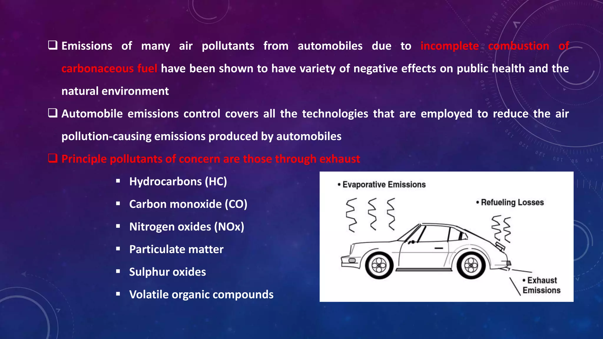
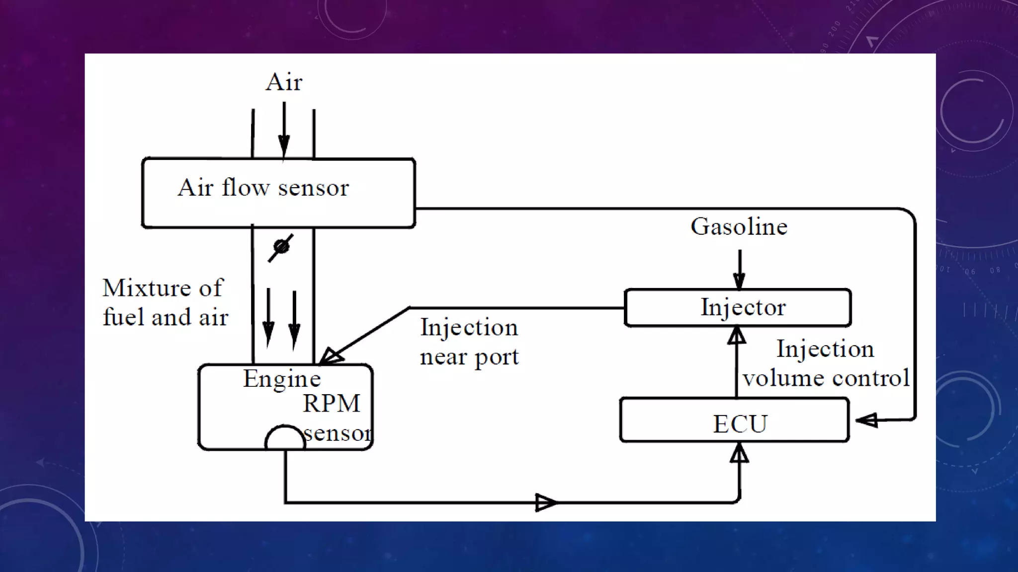
EMISSION CONTROL TECHNOLOGIES 
FOR AUTOMOBILES 
BY 
SHIRIL SAJU
 Emissions of many air pollutants from automobiles due to incomplete combustion of 
carbonaceous fuel have been shown to have variety of negative effects on public health and the 
natural environment 
 Automobile emissions control covers all the technologies that are employed to reduce the air 
pollution-causing emissions produced by automobiles 
 Principle pollutants of concern are those through exhaust 
 Hydrocarbons (HC) 
 Carbon monoxide (CO) 
 Nitrogen oxides (NOx) 
 Particulate matter 
 Sulphur oxides 
 Volatile organic compounds
BHARAT STAGE EMISSION STANDARDS (BS) 
 Emission standards are instituted by the Government of India to regulate the output of air 
pollutants from automobile 
 Based on European regulations (EURO) 
 BS First introduced in 2000 (some other regulations were there from 1983 onwards) 
PRESCRIBED EMISSION LIMITS 
CO (HC + NOx) Sulphur 
gm/Km gm/Km ppm 
BS I 2.72 0.97 
BS II 2.3 0.5 500 
HC NOx 
BS III 2.2 0.2 0.15 350 
BS IV 1 0.1 0.08 50
BS vs. EURO 
 BS stages are of same standards as euro stages in terms of causing pollution 
 i.e. a EURO IV car makes same pollution as that of BS IV 
 Differences are in terms of testing conditions 
 Atmospheric temperature 
Sub-zero temp in Europe and avg 24-28 degree Celsius in India 
 Car speed during testing 
Max 120kmph in Europe and max 90kmph in India 
 Road Conditions
 Bharat norms are lagging behind euro norms by two stages in terms of implementation 
 Higher stage means less pollution 
 Meeting these regulations will need 
 Latest auto-technologies 
 Better Fuel quality 
 New Fuel additives 
lagging period
EMISSION CONTROL TECHNOLOGIES 
• ELECTRONIC FUEL INJECTION SYSTEMS 
• MULTI POINT FUEL INJECTION SYSTEM (MPFI) 
• AIR ASSISTED FUEL INJECTION SYSTEM 
• GASOLINE DIRECT INJECTION SYSTEM 
• COMMON RAIL DIRECT INJECTION SYSTEM (CRDI) 
• CATALYTIC CONVERTERS 
• NANO FUEL ADDITIVES
 Engine efficiency has been steadily improved with improved engine design, more precise 
ignition timing and electronic ignition, more precise fuel metering, and computerized engine 
management. 
 More efficiency => more power => less emission because of better combustion process and 
efficient use of air-fuel mix 
 Advances in engine and vehicle technology continually reduce the toxicity of exhaust leaving 
the engine – Electronic Fuel Injection Systems 
 Technologies to detoxify the exhaust are an essential part of emissions control – Catalytic 
Converter 
 Fuel which contains special nano particles will detoxify the exhaust without any special device- 
Nano fuel additives
ELECTRONIC FUEL INJECTION SYSTEMS 
 Inherent parts an Electronic Fuel Injection (EFI) system 
 Fuel Injectors- The fuel injector sprays the appropriate amount of fuel as directed by the vehicle's 
on-board computer (ECU) 
 Fuel pump- The fuel pump sends the fuel from the gas tank through the fuel lines and to the 
throttle body or fuel rail for delivery to the combustion chamber via the fuel injectors 
 Engine Control Unit (ECU)- determines the amount of fuel needed according to the driving 
conditions. The engine control unit, located within the engine compartment, follows a program 
that gives the criteria for how much fuel is delivered in various situations. Programming of ECU is 
basically called engine tuning. 
 Sensors- Sensors located within the vehicle fuelling system help the engine control unit determine 
when certain functions need to happen. Crank and Cam Position Sensor, Airflow Sensor and 
Exhaust Gas Oxygen Sensor are important.
MULTI POINT FUEL INJECTION SYSTEM (MPFI)- for Petrol Engines 
 Carburetor and SPFI was not able to deliver uniform air-fuel mixture into different cylinders 
 MPFI- to supply proper ratio of air-fuel mixture to the cylinders by electrically injecting fuel in 
accordance with various driving conditions 
 More accurate amount of air-fuel mixture will be supplied in this injection system. As a result complete 
combustion will take place. This leads to effective utilization of fuel supplied and hence low emission 
level 
 Fuel was delivered to outside the cylinder, just upstream of the intake valve for that cylinder 
 Types of MPFI 
 For all cylinders together - simultaneous 
 For a group of cylinders - batched 
 For each cylinder sequentially according each ones intake stroke - sequential
GASOLINE DIRECT IGNITION SYSTEM (GDi)- for Petrol Engines 
 Direct fuel injection is a fuel-delivery technology that allows gasoline engines to burn fuel more 
efficiently, resulting in more power, cleaner emissions, and increased fuel economy 
 In a direct-injection system, the air and gasoline are not pre-mixed; air comes in via the intake 
manifold, while the gasoline is injected directly into the cylinder 
 Combined with ultra-precise computer management, direct injection allows more accurate control 
over fuel metering (the amount of fuel injected) and injection timing (exactly when the fuel is 
introduced into the cylinder)
COMMON RAIL DIRECT IGNITION SYSTEM (CRDi)- for petrol and diesel engines 
 Modern variant of direct injection system- GDi uses CRDi technology- so the term more significant to 
diesel engines 
 Direct injection of the fuel into the cylinders of a diesel engine via a single, common line, called the 
common rail which is connected to all the fuel injectors 
 More accurately measured and timed mixture spray in the combustion chamber significantly reducing 
unburned fuel gives CRDi the potential to meet future emission guidelines such as Euro V 
 Ordinary diesel direct fuel-injection systems have to build up pressure anew for each and every 
injection cycle, the new common rail (line) engines maintain constant pressure regardless of the 
injection sequence. This pressure then remains permanently available throughout the fuel line. 
 The engine's electronic timing regulates injection pressure according to engine speed and load 
 CRDi engines are now being used in almost all Mercedes-Benz, Toyota, Hyundai, Ford and many other 
diesel automobiles
AIR ASSISTED FUEL IGNITION SYSTEM-not very common 
 Air is mixed with fuel at high pressure and is directly injected into the cylinder 
 The rich mixture is injected during the suction stroke (petrol engine) or compression stroke (diesel 
engine) 
 The time of injection and duration of injection depends on the load, speed and other parameters and 
will be as guided by ECU 
 Air compressor driven by the engine is used for obtaining the pressurized air 
 High pressure fuel pump is used for obtaining the pressurized fuel 
 Fuel will be injected as more number of atomized particles which results in more surface area, better 
combustion and less emission 
SINGLE FLUID FUEL INJECTOR 
AIR ASSISTED FUEL INJECTOR
Injection 
quantity 
5 mg 
Single Fluid injector 
30 micron SMD 
471500 droplets 
Total surface area : 14cm2 
8 micron SMD 
24,900,000 droplets 
Total surface area : 50cm2 
Better 
atomization 
Air assisted direct injector 
Fuel 
Economy/ 
Low 
Emission
CATALYTIC CONVERTERS 
 The use of catalytic converters leads to a dramatic reduction in the emissions of CO, HC and NOx 
 The catalytic converter is a device fitted into the front part of the exhaust system as close as 
physically possible to the engine 
 It works with a combination of heat and a precious metal catalyst 
 The converter is constructed of a case which houses, a normally ceramic, honeycomb monolith, the 
internal surfaces of which are coated with a combination of noble metals 
 Endways on this monolith is visually similar to drinking straws, with hundreds of flow channels, to 
increase surface area, that allow gases to come into contact with the catalysts material 
 In a catalytic converter, there are two types of catalysts at work, oxidation catalyst and reduction 
catalyst
 Reduction catalyst is the first stage of the catalytic converter. It uses platinum and rhodium to help 
reduce the NOx emissions 
 When an NO or NO2 molecule contacts the catalyst, the catalyst rips the nitrogen atom out of the 
molecule and holds on to it, freeing the oxygen in the form of O2 
 The nitrogen atoms bond with other nitrogen atoms that are also stuck to the catalyst, forming N2 
 2NO => N2 + O2 or 2NO2 => N2 + 2O2 
 The oxidation catalyst is the second stage of the catalytic converter. It reduces the unburned 
hydrocarbons and carbon monoxide by burning(oxidizing) them over a platinum and palladium 
catalyst. This catalyst aids the reaction of the CO and HC with the remaining oxygen in the exhaust 
gas. 
 Example : 2CO + O2 => 2CO2
Emission  control technologies for automobiles

Emission control technologies for automobiles

  • 1.
    EMISSION CONTROL TECHNOLOGIES FOR AUTOMOBILES BY SHIRIL SAJU
  • 2.
     Emissions ofmany air pollutants from automobiles due to incomplete combustion of carbonaceous fuel have been shown to have variety of negative effects on public health and the natural environment  Automobile emissions control covers all the technologies that are employed to reduce the air pollution-causing emissions produced by automobiles  Principle pollutants of concern are those through exhaust  Hydrocarbons (HC)  Carbon monoxide (CO)  Nitrogen oxides (NOx)  Particulate matter  Sulphur oxides  Volatile organic compounds
  • 3.
    BHARAT STAGE EMISSIONSTANDARDS (BS)  Emission standards are instituted by the Government of India to regulate the output of air pollutants from automobile  Based on European regulations (EURO)  BS First introduced in 2000 (some other regulations were there from 1983 onwards) PRESCRIBED EMISSION LIMITS CO (HC + NOx) Sulphur gm/Km gm/Km ppm BS I 2.72 0.97 BS II 2.3 0.5 500 HC NOx BS III 2.2 0.2 0.15 350 BS IV 1 0.1 0.08 50
  • 4.
    BS vs. EURO  BS stages are of same standards as euro stages in terms of causing pollution  i.e. a EURO IV car makes same pollution as that of BS IV  Differences are in terms of testing conditions  Atmospheric temperature Sub-zero temp in Europe and avg 24-28 degree Celsius in India  Car speed during testing Max 120kmph in Europe and max 90kmph in India  Road Conditions
  • 5.
     Bharat normsare lagging behind euro norms by two stages in terms of implementation  Higher stage means less pollution  Meeting these regulations will need  Latest auto-technologies  Better Fuel quality  New Fuel additives lagging period
  • 6.
    EMISSION CONTROL TECHNOLOGIES • ELECTRONIC FUEL INJECTION SYSTEMS • MULTI POINT FUEL INJECTION SYSTEM (MPFI) • AIR ASSISTED FUEL INJECTION SYSTEM • GASOLINE DIRECT INJECTION SYSTEM • COMMON RAIL DIRECT INJECTION SYSTEM (CRDI) • CATALYTIC CONVERTERS • NANO FUEL ADDITIVES
  • 7.
     Engine efficiencyhas been steadily improved with improved engine design, more precise ignition timing and electronic ignition, more precise fuel metering, and computerized engine management.  More efficiency => more power => less emission because of better combustion process and efficient use of air-fuel mix  Advances in engine and vehicle technology continually reduce the toxicity of exhaust leaving the engine – Electronic Fuel Injection Systems  Technologies to detoxify the exhaust are an essential part of emissions control – Catalytic Converter  Fuel which contains special nano particles will detoxify the exhaust without any special device- Nano fuel additives
  • 8.
    ELECTRONIC FUEL INJECTIONSYSTEMS  Inherent parts an Electronic Fuel Injection (EFI) system  Fuel Injectors- The fuel injector sprays the appropriate amount of fuel as directed by the vehicle's on-board computer (ECU)  Fuel pump- The fuel pump sends the fuel from the gas tank through the fuel lines and to the throttle body or fuel rail for delivery to the combustion chamber via the fuel injectors  Engine Control Unit (ECU)- determines the amount of fuel needed according to the driving conditions. The engine control unit, located within the engine compartment, follows a program that gives the criteria for how much fuel is delivered in various situations. Programming of ECU is basically called engine tuning.  Sensors- Sensors located within the vehicle fuelling system help the engine control unit determine when certain functions need to happen. Crank and Cam Position Sensor, Airflow Sensor and Exhaust Gas Oxygen Sensor are important.
  • 9.
    MULTI POINT FUELINJECTION SYSTEM (MPFI)- for Petrol Engines  Carburetor and SPFI was not able to deliver uniform air-fuel mixture into different cylinders  MPFI- to supply proper ratio of air-fuel mixture to the cylinders by electrically injecting fuel in accordance with various driving conditions  More accurate amount of air-fuel mixture will be supplied in this injection system. As a result complete combustion will take place. This leads to effective utilization of fuel supplied and hence low emission level  Fuel was delivered to outside the cylinder, just upstream of the intake valve for that cylinder  Types of MPFI  For all cylinders together - simultaneous  For a group of cylinders - batched  For each cylinder sequentially according each ones intake stroke - sequential
  • 11.
    GASOLINE DIRECT IGNITIONSYSTEM (GDi)- for Petrol Engines  Direct fuel injection is a fuel-delivery technology that allows gasoline engines to burn fuel more efficiently, resulting in more power, cleaner emissions, and increased fuel economy  In a direct-injection system, the air and gasoline are not pre-mixed; air comes in via the intake manifold, while the gasoline is injected directly into the cylinder  Combined with ultra-precise computer management, direct injection allows more accurate control over fuel metering (the amount of fuel injected) and injection timing (exactly when the fuel is introduced into the cylinder)
  • 12.
    COMMON RAIL DIRECTIGNITION SYSTEM (CRDi)- for petrol and diesel engines  Modern variant of direct injection system- GDi uses CRDi technology- so the term more significant to diesel engines  Direct injection of the fuel into the cylinders of a diesel engine via a single, common line, called the common rail which is connected to all the fuel injectors  More accurately measured and timed mixture spray in the combustion chamber significantly reducing unburned fuel gives CRDi the potential to meet future emission guidelines such as Euro V  Ordinary diesel direct fuel-injection systems have to build up pressure anew for each and every injection cycle, the new common rail (line) engines maintain constant pressure regardless of the injection sequence. This pressure then remains permanently available throughout the fuel line.  The engine's electronic timing regulates injection pressure according to engine speed and load  CRDi engines are now being used in almost all Mercedes-Benz, Toyota, Hyundai, Ford and many other diesel automobiles
  • 14.
    AIR ASSISTED FUELIGNITION SYSTEM-not very common  Air is mixed with fuel at high pressure and is directly injected into the cylinder  The rich mixture is injected during the suction stroke (petrol engine) or compression stroke (diesel engine)  The time of injection and duration of injection depends on the load, speed and other parameters and will be as guided by ECU  Air compressor driven by the engine is used for obtaining the pressurized air  High pressure fuel pump is used for obtaining the pressurized fuel  Fuel will be injected as more number of atomized particles which results in more surface area, better combustion and less emission SINGLE FLUID FUEL INJECTOR AIR ASSISTED FUEL INJECTOR
  • 15.
    Injection quantity 5mg Single Fluid injector 30 micron SMD 471500 droplets Total surface area : 14cm2 8 micron SMD 24,900,000 droplets Total surface area : 50cm2 Better atomization Air assisted direct injector Fuel Economy/ Low Emission
  • 16.
    CATALYTIC CONVERTERS The use of catalytic converters leads to a dramatic reduction in the emissions of CO, HC and NOx  The catalytic converter is a device fitted into the front part of the exhaust system as close as physically possible to the engine  It works with a combination of heat and a precious metal catalyst  The converter is constructed of a case which houses, a normally ceramic, honeycomb monolith, the internal surfaces of which are coated with a combination of noble metals  Endways on this monolith is visually similar to drinking straws, with hundreds of flow channels, to increase surface area, that allow gases to come into contact with the catalysts material  In a catalytic converter, there are two types of catalysts at work, oxidation catalyst and reduction catalyst
  • 18.
     Reduction catalystis the first stage of the catalytic converter. It uses platinum and rhodium to help reduce the NOx emissions  When an NO or NO2 molecule contacts the catalyst, the catalyst rips the nitrogen atom out of the molecule and holds on to it, freeing the oxygen in the form of O2  The nitrogen atoms bond with other nitrogen atoms that are also stuck to the catalyst, forming N2  2NO => N2 + O2 or 2NO2 => N2 + 2O2  The oxidation catalyst is the second stage of the catalytic converter. It reduces the unburned hydrocarbons and carbon monoxide by burning(oxidizing) them over a platinum and palladium catalyst. This catalyst aids the reaction of the CO and HC with the remaining oxygen in the exhaust gas.  Example : 2CO + O2 => 2CO2