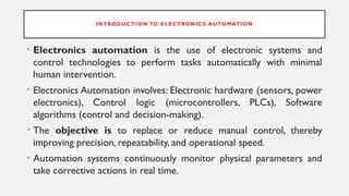
INTRODUCTION TO ELECTRONICS AUTOMATION
• Electronics automation is the use of electronic systems and
control technologies to perform tasks automatically with minimal
human intervention.
• Electronics Automation involves: Electronic hardware (sensors, power
electronics), Control logic (microcontrollers, PLCs), Software
algorithms (control and decision-making).
• The objective is to replace or reduce manual control, thereby
improving precision, repeatability, and operational speed.
• Automation systems continuously monitor physical parameters and
take corrective actions in real time.
5.
NEED FOR AUTOMATION
•Automation is required due to:
• Increasing demand for high-volume and high-quality production.
• Human limitations such as fatigue and error.
• Requirement of continuous (24×7) operation.
• Need for cost reduction and efficient resource utilization.
• In industries such as manufacturing, chemical processing, and
telecommunications, manual control is neither practical nor reliable,
making automation essential.
6.
BASIC COMPONENTS OF
ELECTRONICSAUTOMATION
An electronics automation system consists of four major blocks:
1. Sensors – Convert physical quantities into electrical signals
2. Controllers – Process sensor data and generate control decisions
3.Actuators – Execute physical actions based on controller output
4. Power Electronics – Provide controlled electrical power to actuators
7.
ROLE OF SENSORS
•Sensors act as the interface between the physical world and electronic systems.
• They measure parameters such as:
Temperature
Pressure
Speed
Displacement
Voltage and current.
• The sensor output is usually analog and must be conditioned and converted into
a digital form before being processed by controllers. Accurate sensing is critical
for system stability and performance.
8.
CONTROLLERS IN AUTOMATION
•Controllers are the decision-making units of automation systems.
• Microcontrollers: Used in embedded automation, consumer electronics, and low-cost
systems.
• PLC (Programmable Logic Controller):Designed for industrial environments; highly
reliable, rugged, and easy to program using ladder logic.
• Industrial Computers: Used in advanced automation requiring high computational
power.
• Controllers implement control algorithms such as ON–OFF, PID, or adaptive control.
9.
ACTUATORS
• Actuators convertelectrical control signals into mechanical or physical action.
• Common actuators include:
• DC and AC motors
• Stepper and servo motors
• Relays
• Solenoids (When electric current flows through a coil of wire, it creates a
magnetic field that moves a metal plunger in or out.)
• For example, in an automated conveyor system, motors act as actuators to
move materials based on controller commands.
APPLICATIONS OF ELECTRONICS
AUTOMATION
•Industrial manufacturing
• Home automation (smart lighting, security)
• Robotics
• Automotive systems
• Medical equipment
• Energy management systems
12.
ADVANTAGES OF ELECTRONICS
AUTOMATION
•High efficiency and accuracy
• Reduced human involvement in hazardous environments
• Consistent product quality
• Scalability and flexibility
• Continuous operation without fatigue
13.
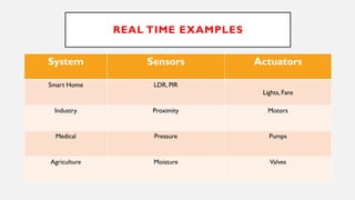
REAL TIME EXAMPLES
SystemSensors Actuators
Smart Home LDR, PIR
Lights, Fans
Industry Proximity Motors
Medical Pressure Pumps
Agriculture Moisture Valves
UNIT 1: SENSORSUSED IN ELECTRONICS
AUTOMATION
Motion Sensor:
• A motion sensor is an electronic device that detects movement of people or
objects and converts it into an electrical signal.
• It is widely used in automation, security, and smart systems.
1. PIR (Passive Infrared) Sensor (Most common)
2. Ultrasonic Motion Sensor
3. Microwave Motion Sensor
4. Infrared Beam Sensor
17.
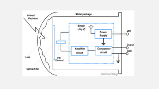
PIR MOTION SENSOR
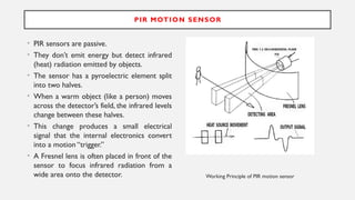
•PIR sensors are passive.
• They don’t emit energy but detect infrared
(heat) radiation emitted by objects.
• The sensor has a pyroelectric element split
into two halves.
• When a warm object (like a person) moves
across the detector’s field, the infrared levels
change between these halves.
• This change produces a small electrical
signal that the internal electronics convert
into a motion “trigger.”
• A Fresnel lens is often placed in front of the
sensor to focus infrared radiation from a
wide area onto the detector. Working Principle of PIR motion sensor
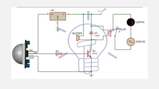
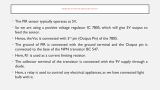
W O RK I N G O F M O T I O N D E T E C T O R C I R C U I T
• The PIR sensor typically operates at 5V,
• So we are using a positive voltage regulator IC 7805, which will give 5V output to
feed the sensor.
• Hence, theVcc is connected with 3rd
pin (Output Pin) of the 7805.
• The ground of PIR is connected with the ground terminal and the Output pin is
connected to the base of the NPN transistor BC 547.
• Here, R1 is used as a current limiting resistor.
• The collector terminal of the transistor is connected with the 9V supply through a
diode.
• Here, a relay is used to control any electrical appliances, as we have connected light
bulb with it.
21.
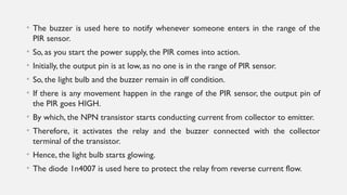
• The buzzeris used here to notify whenever someone enters in the range of the
PIR sensor.
• So, as you start the power supply, the PIR comes into action.
• Initially, the output pin is at low, as no one is in the range of PIR sensor.
• So, the light bulb and the buzzer remain in off condition.
• If there is any movement happen in the range of the PIR sensor, the output pin of
the PIR goes HIGH.
• By which, the NPN transistor starts conducting current from collector to emitter.
• Therefore, it activates the relay and the buzzer connected with the collector
terminal of the transistor.
• Hence, the light bulb starts glowing.
• The diode 1n4007 is used here to protect the relay from reverse current flow.