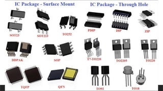
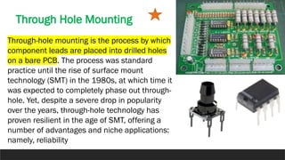
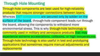
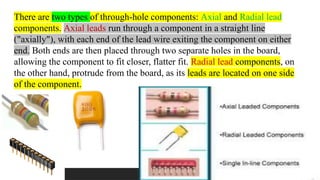
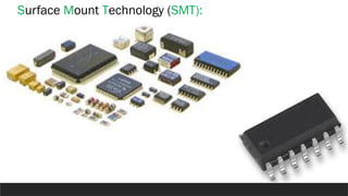
Electronic
Workshop
CHAPTER 2
Types of components used in PCB
In recent years, semiconductor packaging has evolved with an
increased demand for greater functionality, smaller size, and
added utility. A modern PCBA design has two main methods
for mounting components onto a PCB: Through-Hole Mounting
and Surface Mounting.
Through Hole Mounting
Through-hole mounting is the process by which
component leads are placed into drilled holes
on a bare PCB. The process was standard
practice until the rise of surface mount
technology (SMT) in the 1980s, at which time it
was expected to completely phase out through-
hole. Yet, despite a severe drop in popularity
over the years, through-hole technology has
proven resilient in the age of SMT, offering a
number of advantages and niche applications:
namely, reliability
Through-hole components are best used for high-reliability
products that require stronger connections between layers.
Whereas SMT components are secured only by solder on the
surface of the board, through-hole component leads run through
the board, allowing the components to withstand more
environmental stress. This is why through-hole technology is
commonly used in military and aerospace products that may
experience extreme accelerations, collisions, or high temperatures.
Through-hole technology is also useful in test and prototyping
applications that sometimes require manual adjustments and
replacements
Through Hole Mounting
There are two types of through-hole components: Axial and Radial lead
components. Axial leads run through a component in a straight line
("axially"), with each end of the lead wire exiting the component on either
end. Both ends are then placed through two separate holes in the board,
allowing the component to fit closer, flatter fit. Radial lead components, on
the other hand, protrude from the board, as its leads are located on one side
of the component.
Advantages: THM provides stronger mechanical bonds than SMT, making
through-hole ideal for components that might undergo mechanical stress,
such as connectors or transformers. Good for test and prototyping.
Disadvantages: On the bare PCB side, THM requires the drilling holes,
which is expensive and time consuming. THM also limits the available
routing area on any multilayer boards, because the drilled holes must pass
through all the PCB’s layers. On the assembly side, component placement
rates for THM are a fraction of surface mount placement rates, making THM
prohibitively expensive. Further, THM requires the use of wave, selective, or
hand-soldering techniques, which are much less reliable and repeatable
than reflow ovens used for surface mount. Most of all, through-hole
technology requires soldering on both sides of the board, as opposed to
surface-mounts, which only -- for the most part -- require attention to one
side of the board
Surface Mount Technology (SMT):
SMT:
SMT the process by which components are mounted directly onto the
surface of the PCB. Known originally as “planar mounting,” the method was
developed in the 1960s and has grown increasingly popular since the
1980s. Nowadays, virtually all electronic hardware is manufactured using
SMT. It has become essential to PCB design and manufacturing, having
improved the quality and performance of PCBs overall, and has reduced the
costs of processing and handling greatly.
The key differences between SMT and through-hole mounting are:
(a) SMT does not require holes to be drilled through a PCB.
(b) SMT components are much smaller than TH components.
(c) SMT components can be mounted on both side of the board.

ELECTRONIC WORK SHOP USING EASY EDA PROG

  • 1.
  • 2.
    Types of componentsused in PCB In recent years, semiconductor packaging has evolved with an increased demand for greater functionality, smaller size, and added utility. A modern PCBA design has two main methods for mounting components onto a PCB: Through-Hole Mounting and Surface Mounting.
  • 4.
    Through Hole Mounting Through-holemounting is the process by which component leads are placed into drilled holes on a bare PCB. The process was standard practice until the rise of surface mount technology (SMT) in the 1980s, at which time it was expected to completely phase out through- hole. Yet, despite a severe drop in popularity over the years, through-hole technology has proven resilient in the age of SMT, offering a number of advantages and niche applications: namely, reliability
  • 5.
    Through-hole components arebest used for high-reliability products that require stronger connections between layers. Whereas SMT components are secured only by solder on the surface of the board, through-hole component leads run through the board, allowing the components to withstand more environmental stress. This is why through-hole technology is commonly used in military and aerospace products that may experience extreme accelerations, collisions, or high temperatures. Through-hole technology is also useful in test and prototyping applications that sometimes require manual adjustments and replacements Through Hole Mounting
  • 6.
    There are twotypes of through-hole components: Axial and Radial lead components. Axial leads run through a component in a straight line ("axially"), with each end of the lead wire exiting the component on either end. Both ends are then placed through two separate holes in the board, allowing the component to fit closer, flatter fit. Radial lead components, on the other hand, protrude from the board, as its leads are located on one side of the component.
  • 7.
    Advantages: THM providesstronger mechanical bonds than SMT, making through-hole ideal for components that might undergo mechanical stress, such as connectors or transformers. Good for test and prototyping. Disadvantages: On the bare PCB side, THM requires the drilling holes, which is expensive and time consuming. THM also limits the available routing area on any multilayer boards, because the drilled holes must pass through all the PCB’s layers. On the assembly side, component placement rates for THM are a fraction of surface mount placement rates, making THM prohibitively expensive. Further, THM requires the use of wave, selective, or hand-soldering techniques, which are much less reliable and repeatable than reflow ovens used for surface mount. Most of all, through-hole technology requires soldering on both sides of the board, as opposed to surface-mounts, which only -- for the most part -- require attention to one side of the board
  • 8.
  • 9.
    SMT: SMT the processby which components are mounted directly onto the surface of the PCB. Known originally as “planar mounting,” the method was developed in the 1960s and has grown increasingly popular since the 1980s. Nowadays, virtually all electronic hardware is manufactured using SMT. It has become essential to PCB design and manufacturing, having improved the quality and performance of PCBs overall, and has reduced the costs of processing and handling greatly. The key differences between SMT and through-hole mounting are: (a) SMT does not require holes to be drilled through a PCB. (b) SMT components are much smaller than TH components. (c) SMT components can be mounted on both side of the board.