Drier Risk Management GENERIC E (2)
•
0 likes•94 views

This document discusses nozzle sealing system failures that can occur in drier plants and the risks associated with such failures. It notes that leaking nozzles pose a fire risk and can impact safety, production and insurance costs. Current nozzle sealing designs are prone to damage and may not meet pressure standards. A new axial seal design is proposed that is more robust, easier to assemble and maintain, and complies with high pressure standards, reducing risks associated with nozzle failures.

Recommended
Recommended
More Related Content
Viewers also liked
Viewers also liked (11)
Similar to Drier Risk Management GENERIC E (2)
Similar to Drier Risk Management GENERIC E (2) (20)
Drier Risk Management GENERIC E (2)
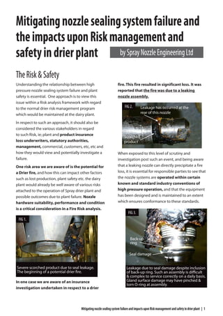
- 1. MitigatingnozzlesealingsystemfailureandimpactsuponRiskmanagementandsafetyindrierplant | 1 TheRisk&Safety Understanding the relationship between high pressure nozzle sealing system failure and plant safety is essential. One approach is to view this issue within a Risk analysis framework with regard to the normal drier risk management program which would be maintained at the dairy plant. In respect to such an approach, it should also be considered the various stakeholders in regard to such Risk, ie; plant and product insurance loss underwriters, statutory authorities, management, commercial, customers, etc, etc and how they would view and potentially investigate a failure. One risk area we are aware of is the potential for a Drier fire, and how this can impact other factors such as lost production, plant safety etc. the dairy plant would already be well aware of various risks attached to the operation of Spray drier plant and possible outcomes due to plant failure. Nozzle hardware suitability, performance and condition is a critical consideration in a Fire Risk analysis. In one case we are aware of an insurance investigation undertaken in respect to a drier fire. This fire resulted in significant loss. It was reported that the fire was due to a leaking nozzle assembly. When exposed to this level of scrutiny and investigation post such an event, and being aware that a leaking nozzle can directly precipitate a fire loss, it is essential for responsible parties to see that the nozzle systems are operated within certain known and standard industry conventions of high pressure operation, and that the equipment has been designed and is maintained to an extent which ensures conformance to these standards. Mitigatingnozzlesealingsystemfailureand theimpactsuponRiskmanagementand safetyindrierplant Leakage has occurred at the rear of this nozzle Scorched product Leakage due to seal damage despite inclusion of back-up ring. Such an assembly is difficult & complex to service correctly on a daily basis. Gland surface damage may have pinched & torn O-ring at assembly. Back-up ring Seal damage bySprayNozzleEngineeringLtd Severe scorched product due to seal leakage. The beginning of a potential drier fire. FIG 1. FIG 3. FIG 2.
- 2. 2 | MitigatingnozzlesealingsystemfailureandimpactsuponRiskmanagementandsafetyindrierplant Observingstandards&improved designcanhelp It is well known in many industries that standards of sealing integrity are covered by widely adopted standards such as AS4716A, along with pressure integrity standards for plant such as ASME B31.3, amongst other very similar international standards. Nozzles can be designed to conform to the required pressure & service duties in observance of such standards and manufacturers can provide design data to support their product duty. Such information should be pursued in any Risk management model for drier safety. Management Systems must exist to ensure that such spray nozzle hardware sealing standards are not easily compromised. This can be achieved through improved hardware design and proper maintenance so as to reduce the likely hood of such a failure in the first instance. Multiple seal gland surface damage due to mishandling. Unsuitable for service. Multiple seal gland surface damage due to lance handling impact on a NEW nozzle and lance. Unsuitable for service. Severe single point damage due to lance handling impact on a NEW nozzle. Unsuitable for service. Damage seal gland surface Even without damage, sealing standards limit such an arrangement to a max. pressure of only 103 barG. FIG 4. Radial seal gland damage with localised impact damage. Note old imbedded seal. New seals should be installed on each run. Unsuitable for service. FIG 5. FIG 6. FIG 7. FIG 8.
- 3. MitigatingnozzlesealingsystemfailureandimpactsuponRiskmanagementandsafetyindrierplant | 3 Typicaldrierpressuresrequire reliablesealingsystemsfitfor purpose We know that leaking nozzles can cause a drier fire, and this is directly related to their ability to reliably seal in their typical operating environment, The following should be understood and considered in respect to a related risk analysis: Most Spray nozzle systems in driers are required to function without failure at pressures typically up to, or in some cases even exceeding, 350 barG. This is a very high pressure by any industry standard. If the nozzle seal fails under these known pressure conditions, what are the likely risks attached to such a failure, and how would such potential risk impact safety, product quality, lost production, etc. In the interests of all concerned, it is important that stakeholders can see that known industry standards of practice have been adopted to help avoid seal failure, material and design failure (amongst a number of other potential failure conditions), particularly in the event that a significant loss has somehow occurred. Damaged seal gland surface compromising sealing integrity Severe seal gland surface damage FIG 9. Typical back up ring extrusion failure due to gland wear. The back up ring is designed to prevent O-ring extrusion. When the back up ring extrudes itself, failure is inevitable. High risk FIG 10. Similarly nozzle carriers (caps) can also exhibit damaged seal gland surfaces compromising sealing integrity. These lance components must also be risk managed. FIG 11. Nozzle carriers must be designed to function safely at the maximum operating pressure of the drier. These carriers have been over-pressured and on the verge of significant stress yield failure. Note stress bulge & crack FIG 12.
- 4. 4 | MitigatingnozzlesealingsystemfailureandimpactsuponRiskmanagementandsafetyindrierplant ReasonsforSealingSystemfailure: ______________________________________________ • PROBLEM: Poorly designed seal gland systems that lend themselves to be easily damaged during normal use and exposed sealing surface at the lance end that is easily damaged by impact during handling. Most dairy plants currently operate spray lances with readily exposed nozzle hardware seal surfaces at their end which are regularly subject to impact during handling, such impact can compromise sealing efficiency and cause failure. Click&Dry® has a Heavy duty female threaded lance fitting with heavily concealed sealing surface which is highly resistant to normal impact damage during lance handling ______________________________________________ • PROBLEM: Poorly maintained nozzle seal gland systems in drier. Seal gland damage has been observed and reported at many dairy sites. In most cases the pressure integrity of such hardware cannot be guaranteed. It is a standing recommendation that the compromised hardware is immediately replaced when such damage is observed. Regular damage inspection is an absolute must. Monitoring of seal gland condition and checking for radial dimensional conformance is critical in any nozzle hardware risk management program. Click&Dry® system will eliminate the need for radial measurement monitoring. ______________________________________________ ________________________________________ • PROBLEM: Seal gland systems that do not comply with known sealing conventions and standards in respect to the operating pressures required. It is known that most sealing glands operated by most dairy plants are of a radial type and do not comply with known sealing standard recommendations and conventions for high pressure operation, specifically, they do not deal with gland gap inherent in such radial seal designs and the resultant potential for O-ring extrusion at pressures exceeding 103.4 BarG, most dairy systems require gland conformance to 350 BarG +. It is also known that required minimal seal gland gap cannot be easily and practically maintained within normal dairy plant operational processes using current designs, even with the adoption of more stringent maintenance programs. Click & Dry® uses a non radial AXIAL SEAL which are a known & published industry preference in high pressure sealing applications since THEY HAVE NO GAPin a face to face contact. Old radial seals without back up rings should only operate at pressures well below typical operating pressures according to typical O-ring standards. Required assembly joint gap of radial seals allows seal extrusion at high pressures. Click&Dry® operates with NO GAP and therefore no seal extrusion can occur. ________________________________________ FIG 13. FIG 15. FIG 14. OLD RADIAL SEAL GLAND GAP Requires assembly joint gap. May allow seal extrusion & leaks at normal operating pressures. Should not exceed 103.4 barG without backup rings Axial compressive seal with NO GAP for use well above typical operating pressures of 350 barG plus. Seal face protection skirts for extra seal face protection NO GAP NEW AXIAL SEAL GLAND SEAL FACE PROTECTION SKIRTS SOLUTION: SOLUTION: SOLUTION:
- 5. MitigatingnozzlesealingsystemfailureandimpactsuponRiskmanagementandsafetyindrierplant | 5 ________________________________________ • PROBLEM: Seal gland systems require allowable material stress due to pressure of operation to comply with the requirement standards such as ASME B31.3. It is not shown that hardware arrangements currently in use by dairy sites comply to such pressure integrity requirements Click&Dry® system is shown to comply with satisfactory operational factors of safety in regard to allowable stress in service. ________________________________________ • PROBLEM: Difficulty in positive assembly and use. Most current nozzle systems in use by dairy sites require great deal of assembly skill and the risk of misalignment of components is high. This can lead to leakage. In particular, if radial seal backup rings are adopted as required, these can be incorrectly installed on the wrong side of the seal or can catch on assembly, compromising the seal before use. These backup rings are also very expensive. Click&Dry® axial seal does not require troublesome backup rings, it also eliminates misalignment of wear parts during assembly (clasp model) which can cause leakage ________________________________________ ________________________________________ Conclusion In conclusion, it can be seen that a significant level of risk in respect to seal gland integrity is currently being carried by dairy sites, whereby if a drier Fire did occur, that this might compromise safety, and that if such an event could be linked to a leaking nozzle, then it might be most difficult to disprove that it was as a result of any of the above mentioned weaknesses in the current nozzle systems. ________________________________________ Adopting the Click & Dry® system delivers dairy sites a state of the art nozzle design, with Design features which improve nozzle seal gland life, reduce the likely hood of handling damage, reduce the likely hood of misalignment during assembly (amongst many other benefits not mentioned here), and most importantly more readily conforms to known sealing standards and conventions for high pressure use, in particular the pressures operated by dairy sites. As such this reduces significantly the risk of leakage, and therefore fire, and the resultant potential compromises to safety) ________________________________________ _________________________________________ • PROBLEM: Lack of vendor technical support in respect to operator training and product information including technical literature and user guidelines along with product care and management accessories. Click&Dry® is a fully supported product in the field with on-site operator training and a comprehensive library of technical support material tailored for field use.Click&Dry® NOZZLE ASSEMBLY GUIDE FOR MAXI FIRST GENERATION SYSTEM O-RING GROOVE IN CAP - NON CLASP SCREW PIN This guide relates to early First Generation O-ring groove in nozzle cap. To reduce bearding and/or increase operating pressures please contact us regarding the new SEAL-IN-DISC SYSTEM now available. WARNING! 1300 Nozzle TECH TIP! ASSEMBLY SHEET #1 Click&Dry 228.3 MPa -48.9 0.0 FIG 16. FIG 17. FIG 18. SOLUTION: SOLUTION: SOLUTION:
- 6. 6 | MitigatingnozzlesealingsystemfailureandimpactsuponRiskmanagementandsafetyindrierplant Addenda I have found in the“Dichtomatik O-Ring Handbook”the following statement Extrusionisaconcernforradialsealswherethereisagap betweenthepistonandtheboreforamaleglandsealor betweentherodandtheboreforafemaleglandseal.Extrusion isnotaconcernforfacesealswherethemetalpartstobesealed aretypicallyinline-to-linecontact Ithinkweshouldagainemphasizethefollowingpoints: • Thereisanincreaseinergonomicsandhandling advantagesastheuserdoesnothavetohandlethefiddly andbrittleback-upringswiththedesign. • Ifback-upringsisnotusedoriscrackedinaradial sealingarrangement,thesealmayfailinhighpressures duetovariousstatementsinO-ringdesignhandbooks worldwide,suchasfromDichtomatikandParker.Thiswill thereforemaketheaxialsealingmethodsaferunderthese conditions. • Needtoemphasizethefeedbackwehavehadinregardsto theuseofback-upringsandhowoftentheyhavecracked orbroken. • Lessconsumablestopurchase ParkerO-ringHandbooksaysofmetalnogap: Commentsfromourengineer,CharlesVuong: