Downloaded 196 times
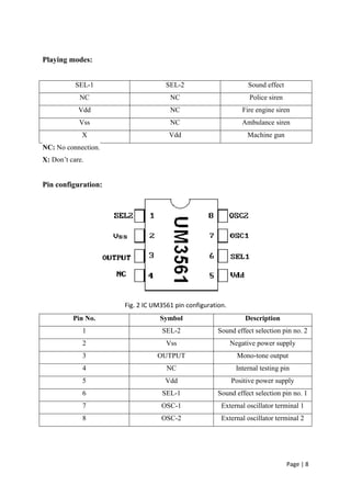
![Page | 12
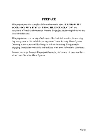
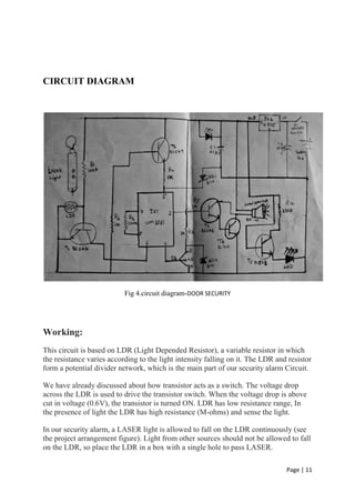
In this situation, the resistance offered by LDR is too low, since the LASER light is
continuously allowed to fall on the LDR surface. Thus the voltage drop across the
LDR is also low [V=IR (Ohm’s law)] which is insufficient to turn on the transistor, so
the transistor remains in OFF state.
When a person (eg: thief) makes a block to the continuous flow of LASER beam, then
the light falling on the LDR gets blocked or interrupted. Thus its resistance increases
to a high value in the order (M-ohms) range. While resistance increases the voltage
drop also increases, when this voltage drop exceeds the cut in voltage of the Silicon
NPN transistor (BC547), it will turn ON.
Then current from Vcc starts flowing to ground via the IC UM3561 to speaker and
transistor, which makes the sound, the musical tone from the security alarm gives the
indication of some security failures.
Thus in this circuit we built a laser security alarm which uses a laser light and a laser
light detector circuit, so when any person or object crossover the laser line the security
alarm will ring & its gets activated when someone crosses it.](https://image.slidesharecdn.com/door-170131010153/85/LASER-BASED-DOOR-SECURITY-SYSTEM-USING-SIREN-GENERATOR-12-320.jpg)


This document is a project report on a laser-based door security system using a siren generator. It describes the system's components, which include a UM3561 integrated circuit, transistors, resistors, capacitors, LEDs, and a battery. The circuit uses a laser beam and light dependent resistor (LDR) to detect intruders. When the laser beam is blocked, the LDR resistance changes and triggers the alarm circuit to sound a siren using the UM3561 IC. The report provides the circuit diagram, descriptions of major components, advantages and applications of the system. It concludes that home security technology continues to advance while security remains an important concern.


![batch_10_ppt[1][1].pptx hhtffffvhhhhhbbbv](https://cdn.slidesharecdn.com/ss_thumbnails/batch10ppt11-240830052746-76310ef2-thumbnail.jpg?width=640&height=640&fit=bounds)


