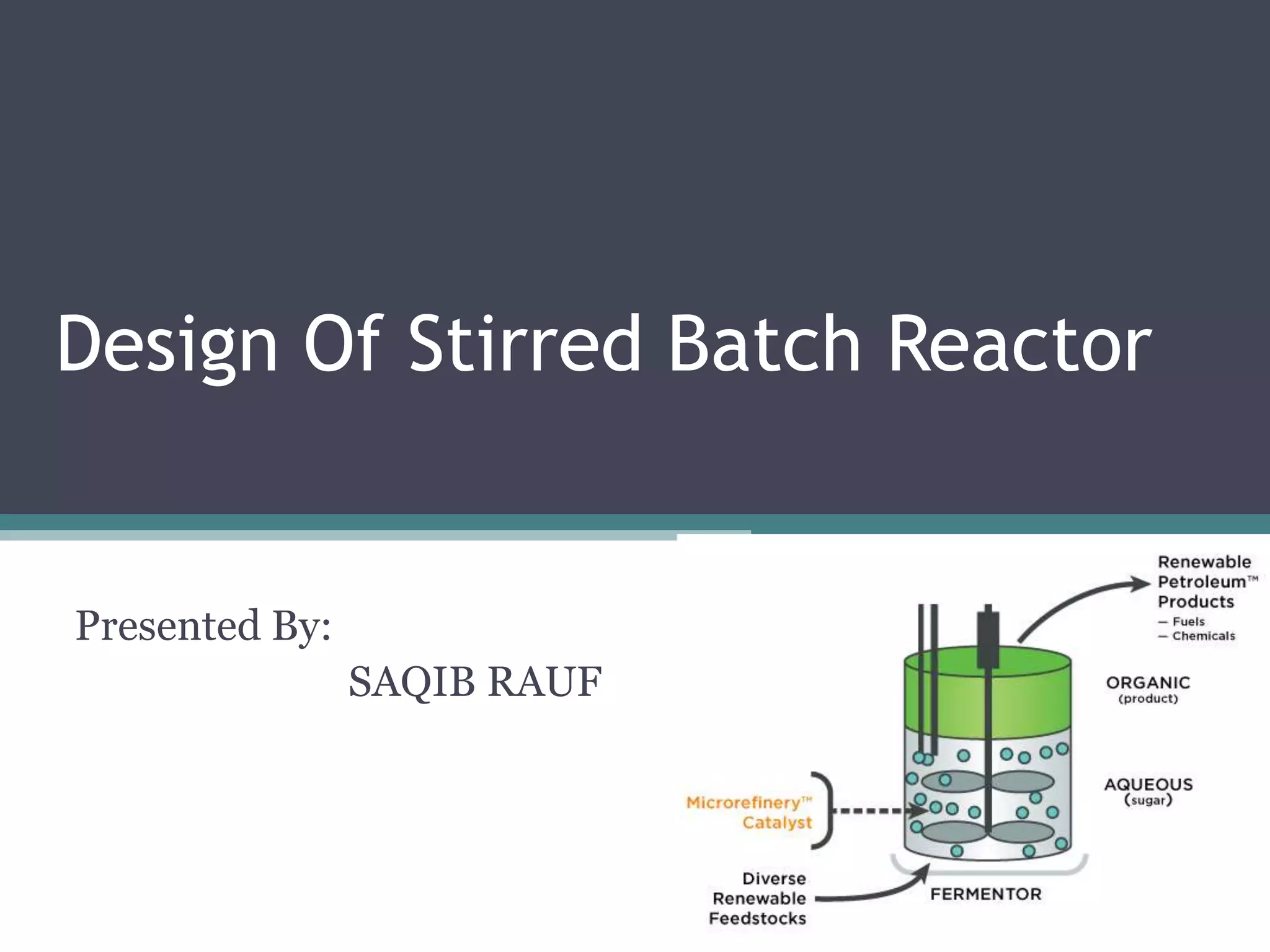
The document describes the design of a batch stirred tank reactor for producing industrial alcohol through fermentation. Key details include:
- The reactor will be a jacketed, stirred tank reactor with a volume of 377m3, 10m height, 6.8m diameter, and carbon steel construction.
- It will operate at 32°C and 1.8 atm with a 52 hour batch time and use a torispherical head.
- Cooling will be provided by a 17m2 jacket using 33 tons/hr of cooling water from 20-28°C.
- Agitation will be from three 6-bladed impellers 2.2m in diameter running at 44 RPM and requiring 60
In this document
Powered by AI
Introduction to bioreactors, definition and types including batch, fed-batch, and continuous systems.
Introduction to bioreactors, definition and types including batch, fed-batch, and continuous systems.
Overview of the fermentation process, reaction equation, and thermodynamic data related to ethanol production.
Key aspects of reactor design including selection, mechanical design, and specifics of batch reactors.
Details on batch reactor operation times, conversion rates, and specific calculations for yeast fermentation.
Details on batch reactor operation times, conversion rates, and specific calculations for yeast fermentation.
Calculation of fermenter volume based on batch time, density, and allowances for free space.
Mechanical design considerations, including wall thickness calculations and selection of reactor heads.Agitator design specifications, including dimensions and power requirements for operation.
Heat transfer calculations for reactors, including cooling requirements and removal of heat.
Identification of major components for fermenters and agitators, including specifications and materials.
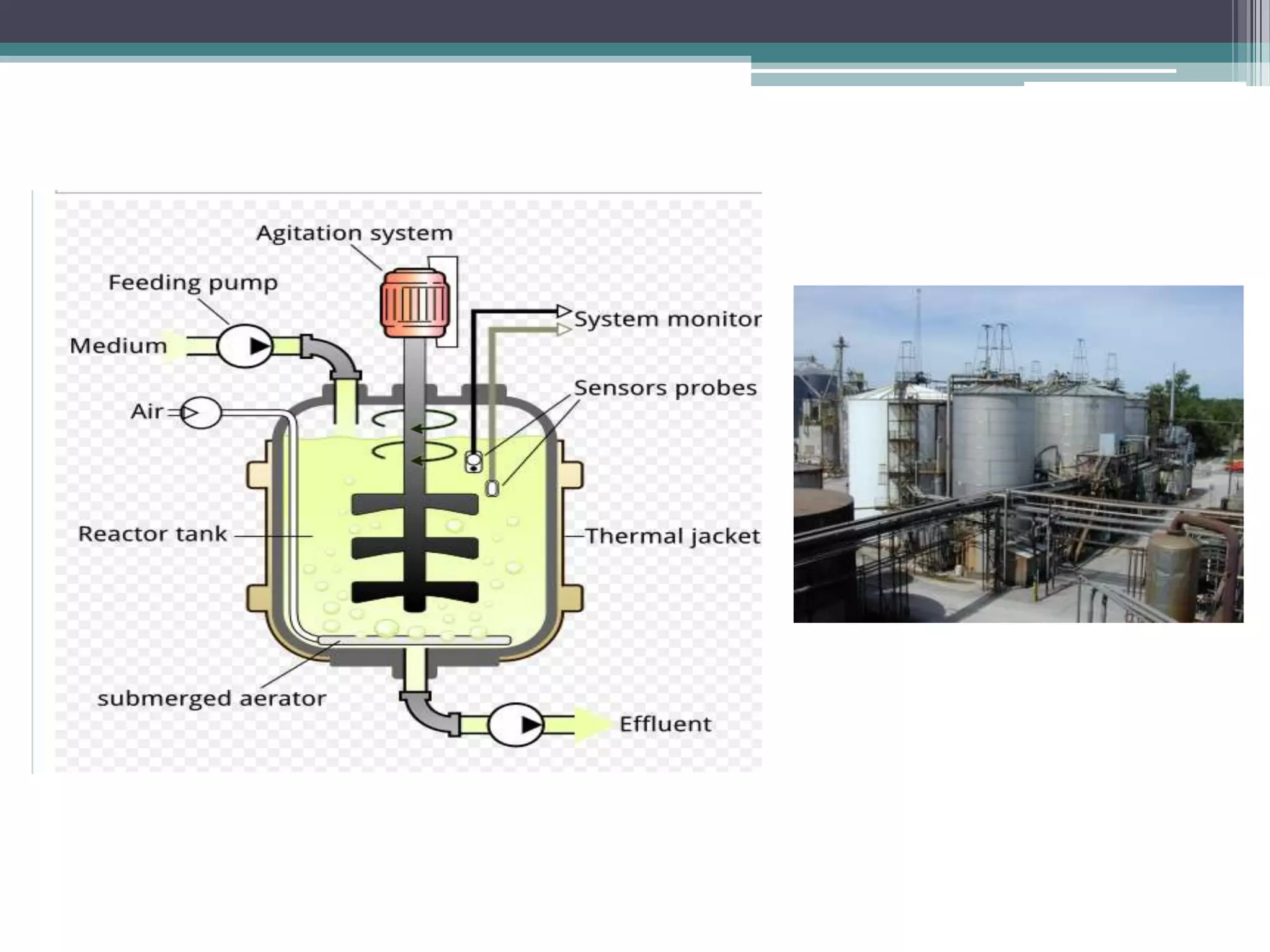
What is bio-reactor
•A bioreactor may refer to any manufactured or
engineered device or system that supports a
biologically active environment
• In one case, a bioreactor is a vessel in which a
chemical process is carried out which involves
organisms or biochemically active substances
derived from such organisms. This process can
either be aerobic or anaerobic. These bioreactors are
commonly cylindrical, ranging in size from litres to
cubic metres, and are often made of stainless steel.
5.
Cont..
• A bioreactormay also refer to a device or system
meant to grow cells or tissues in the context of
cell culture. These devices are being developed
for use in tissue engineering or biochemical
engineering
6.
Classification of bio-reactors
•On the basis of mode of operation, bioreactor
may be classified as
• Batch
• Fed batch
• continuous
• Organisms growing in bioreactors may be
• Suspended
• Immobilized
7.
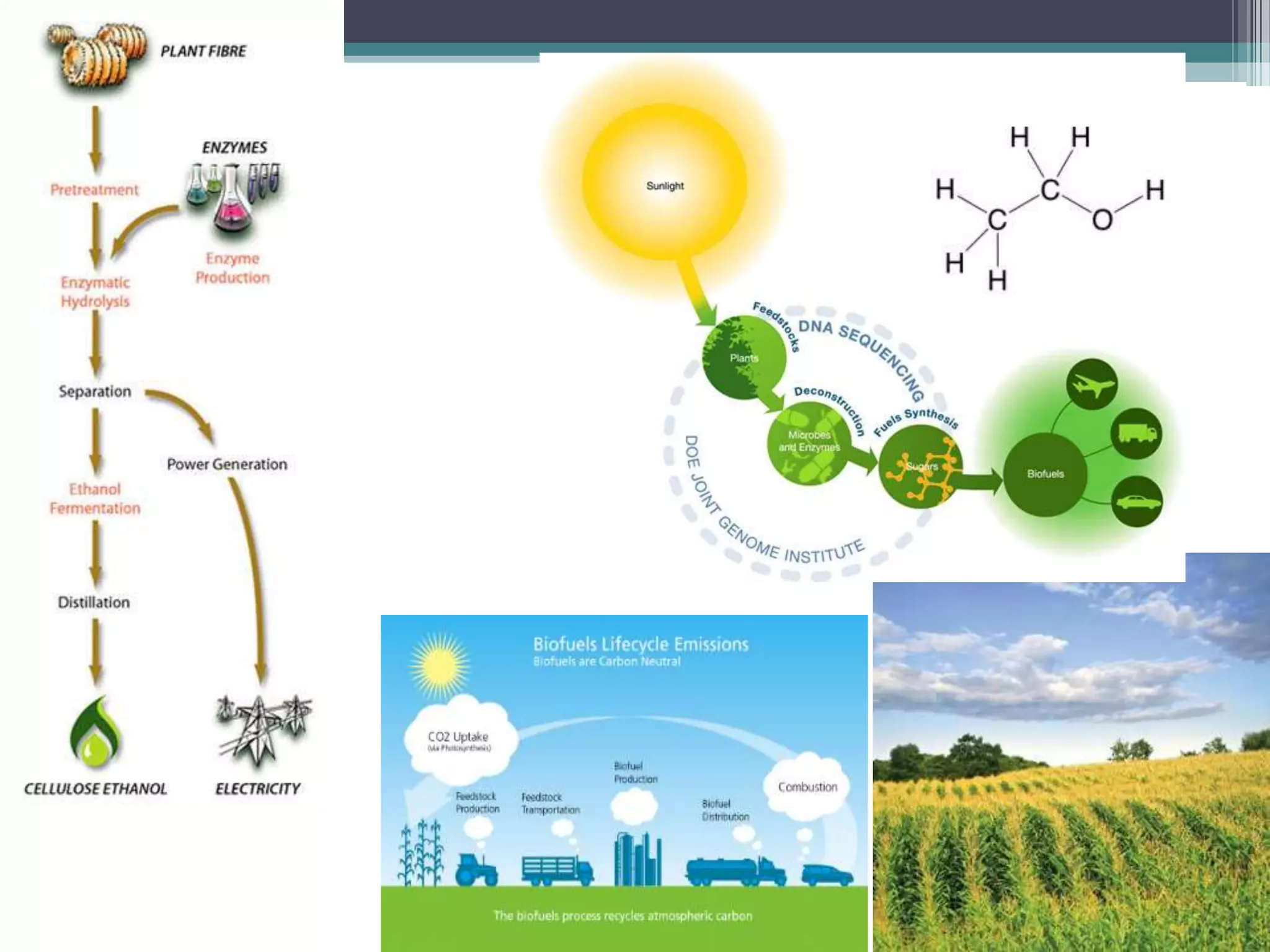
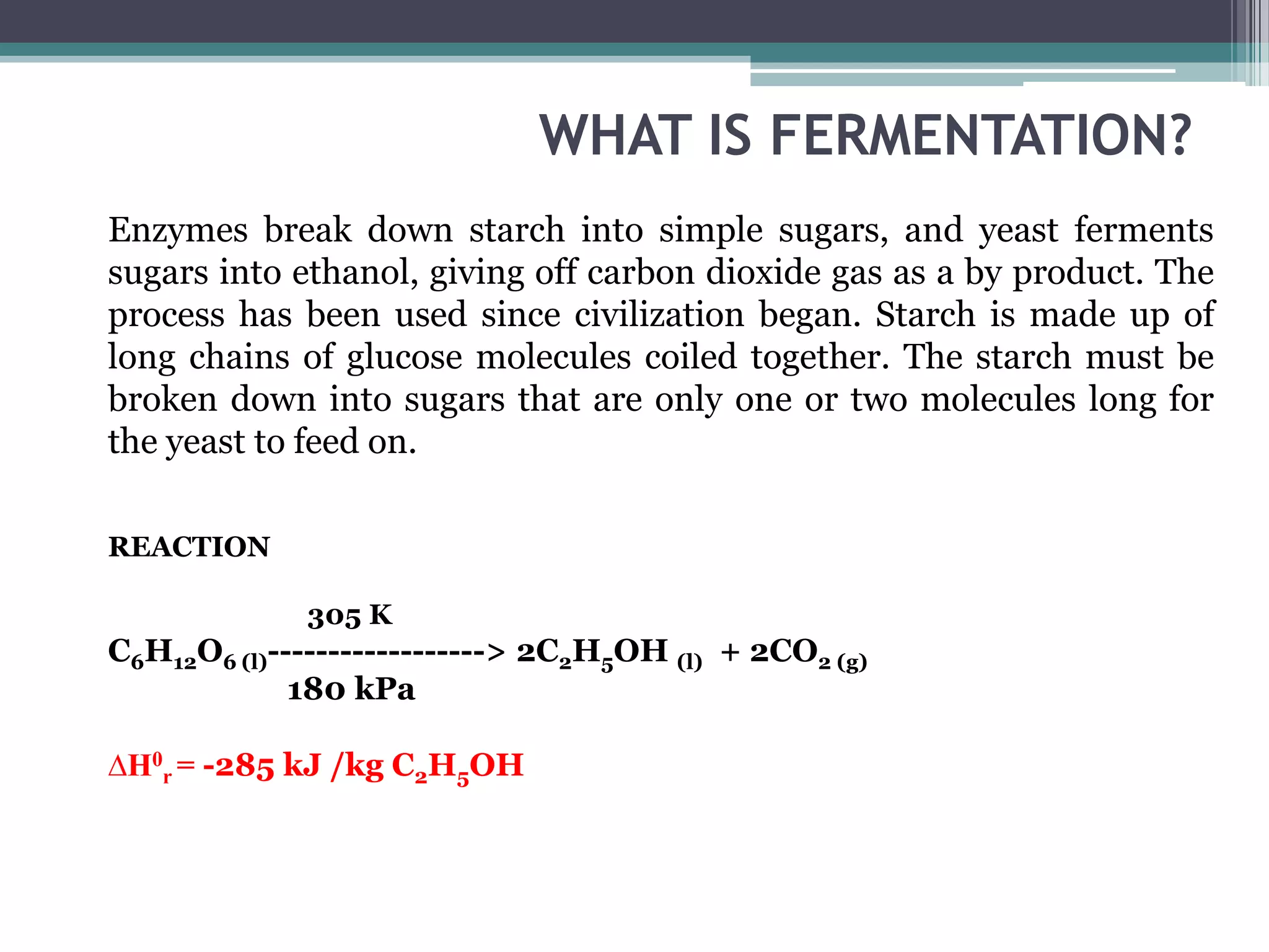
WHAT IS FERMENTATION?
Enzymesbreak down starch into simple sugars, and yeast ferments
sugars into ethanol, giving off carbon dioxide gas as a by product. The
process has been used since civilization began. Starch is made up of
long chains of glucose molecules coiled together. The starch must be
broken down into sugars that are only one or two molecules long for
the yeast to feed on.
REACTION
305 K
C6H12O6 (l)------------------> 2C2H5OH (l) + 2CO2 (g)
180 kPa
∆H0r = -285 kJ /kg C2H5OH
8.
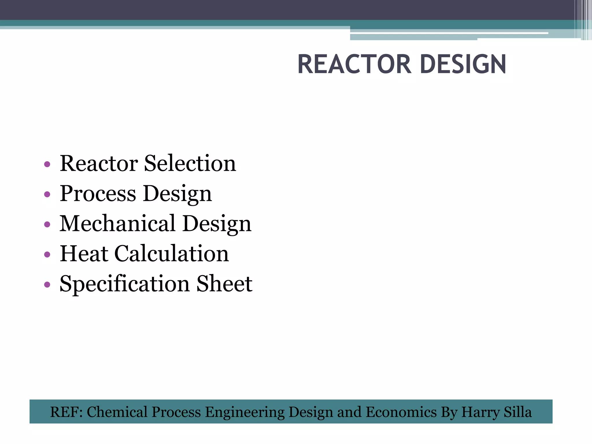
REACTOR DESIGN
• Reactor Selection
• Process Design
• Mechanical Design
• Heat Calculation
• Specification Sheet
REF: Chemical Process Engineering Design and Economics By Harry Silla
9.
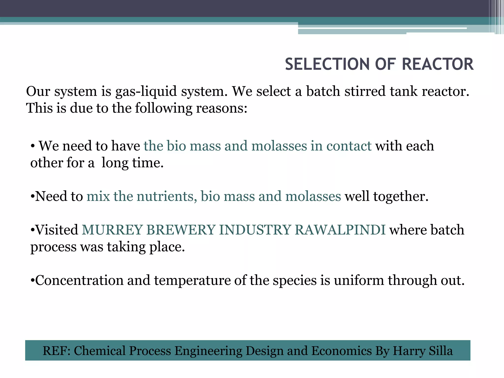
SELECTION OF REACTOR
Oursystem is gas-liquid system. We select a batch stirred tank reactor.
This is due to the following reasons:
• We need to have the bio mass and molasses in contact with each
other for a long time.
•Need to mix the nutrients, bio mass and molasses well together.
•Visited MURREY BREWERY INDUSTRY RAWALPINDI where batch
process was taking place.
•Concentration and temperature of the species is uniform through out.
REF: Chemical Process Engineering Design and Economics By Harry Silla
10.
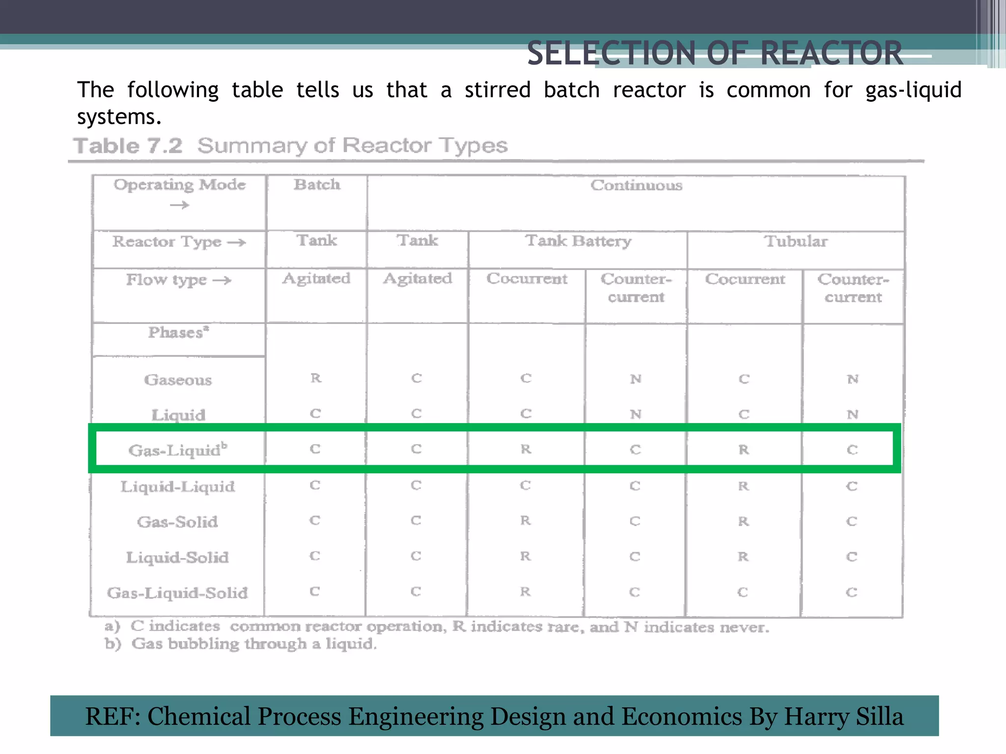
SELECTION OF REACTOR
Thefollowing table tells us that a stirred batch reactor is common for gas-liquid
systems.
REF: Chemical Process Engineering Design and Economics By Harry Silla
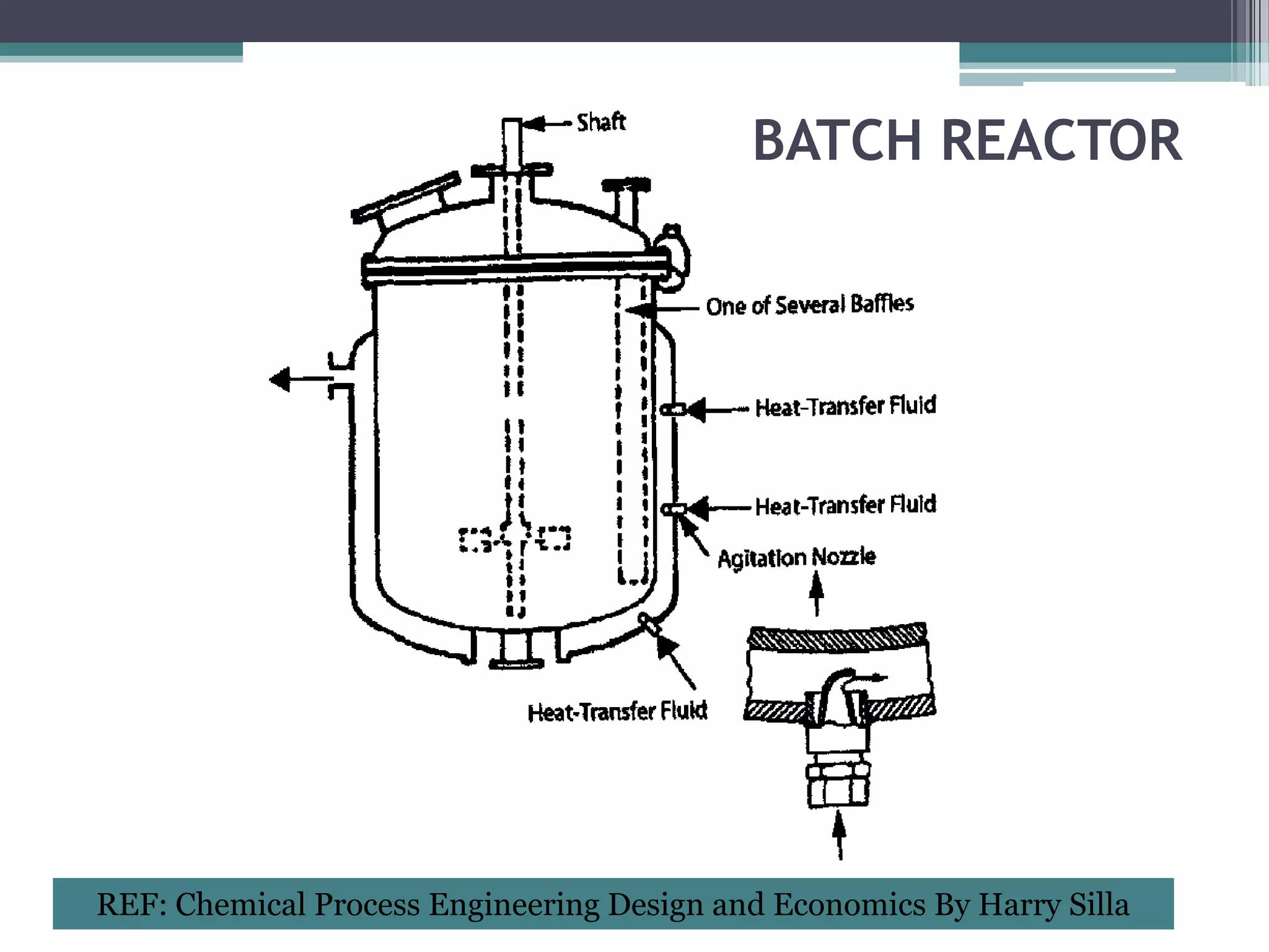
BATCH REACTOR
•Fermenter modeledas a batch reactor.
•Batch reactor consists of an agitator and a
jacket around it for cooling purposes.
•Reactants are filled in and allowed to react for a
certain period of time without them exiting.
•Jacket consists of agitation nozzles for
providing higher turbulence and hence better
heat transfer.
REF: Chemical Process Engineering Design and Economics By Harry Silla
13.
BATCH REACTOR
•Fermenter modeledas a batch reactor.
•Batch reactor consists of an agitator and a
jacket around it for cooling purposes.
•Reactants are filled in and allowed to react for a
certain period of time without them exiting.
•Jacket consists of agitation nozzles for
providing higher turbulence and hence better
heat transfer.
REF: Chemical Process Engineering Design and Economics By Harry Silla
14.
BATCH REACTOR
•There are2 fermenters installed in parallel.
•According to a journal, the conversion is 70 %
and for that conversion the reaction time is 48
hrs.
•2 fermenters are used because 1 would give us
very large dimensions.
16.
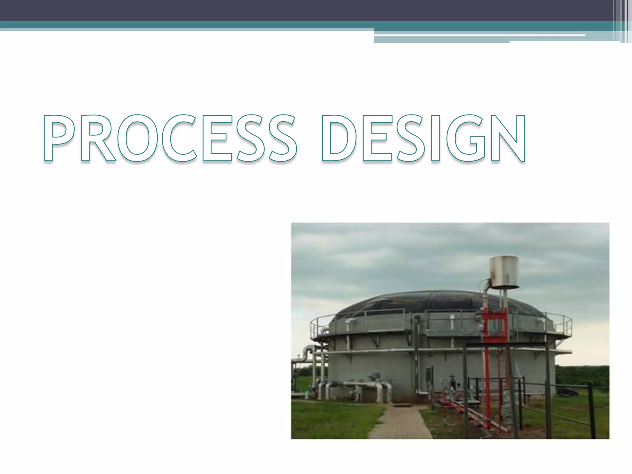
PROCESS DESIGN
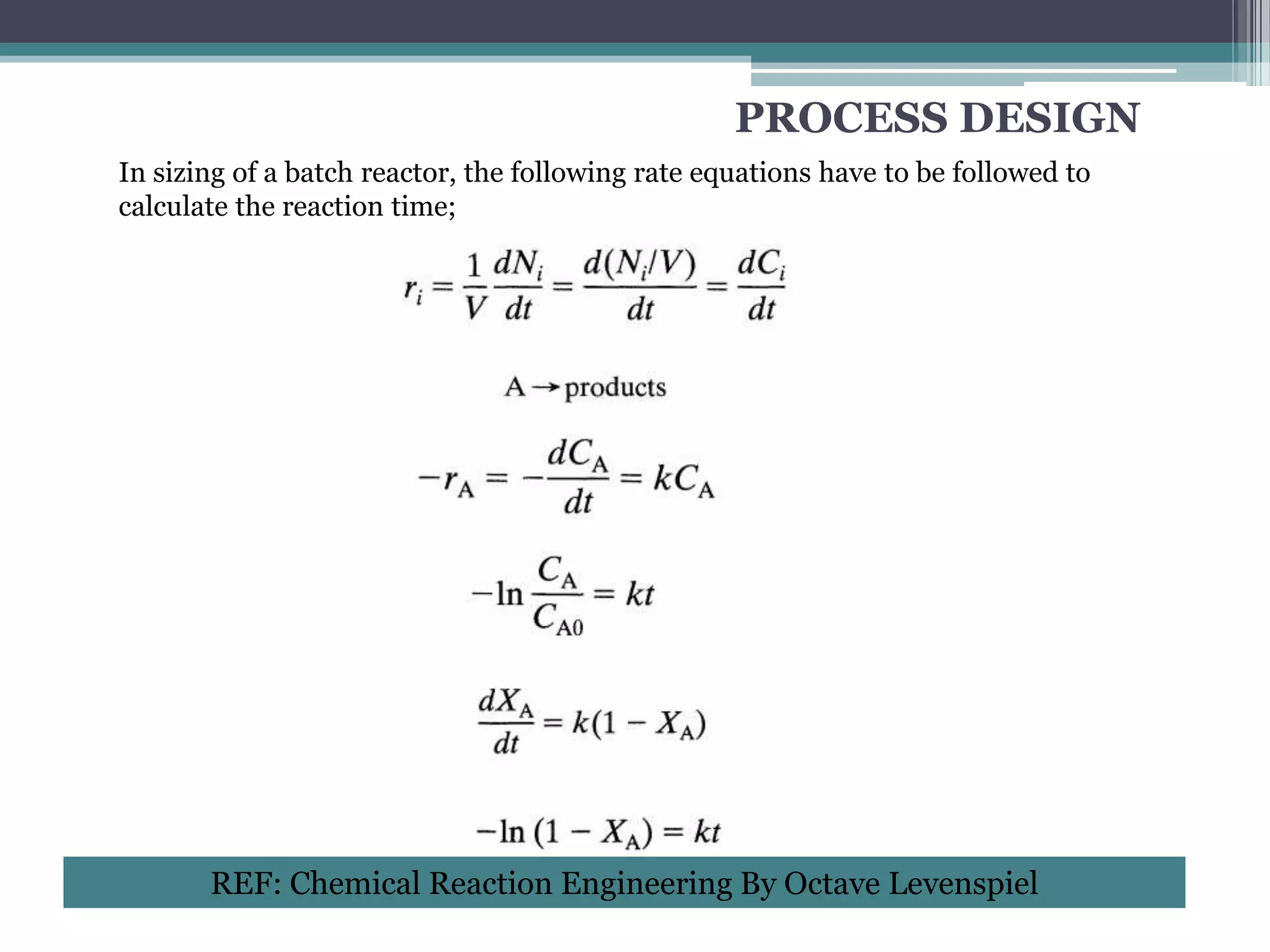
In sizingof a batch reactor, the following rate equations have to be followed to
calculate the reaction time;
REF: Chemical Reaction Engineering By Octave Levenspiel
17.
PROCESS DESIGN
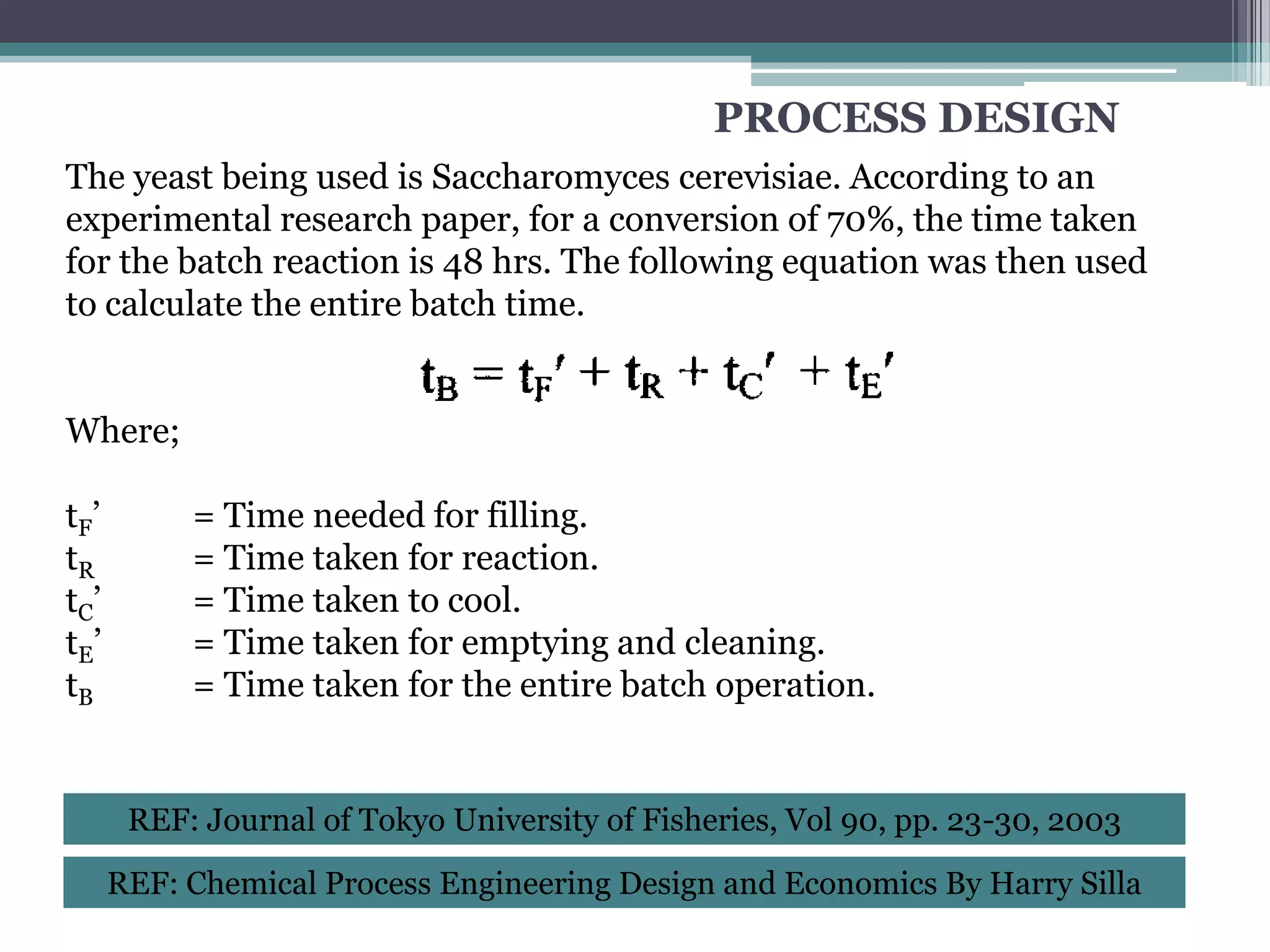
The yeastbeing used is Saccharomyces cerevisiae. According to an
experimental research paper, for a conversion of 70%, the time taken
for the batch reaction is 48 hrs. The following equation was then used
to calculate the entire batch time.
Where;
tF ’ = Time needed for filling.
tR = Time taken for reaction.
tC’ = Time taken to cool.
tE ’ = Time taken for emptying and cleaning.
tB = Time taken for the entire batch operation.
REF: Journal of Tokyo University of Fisheries, Vol 90, pp. 23-30, 2003
REF: Chemical Process Engineering Design and Economics By Harry Silla
18.
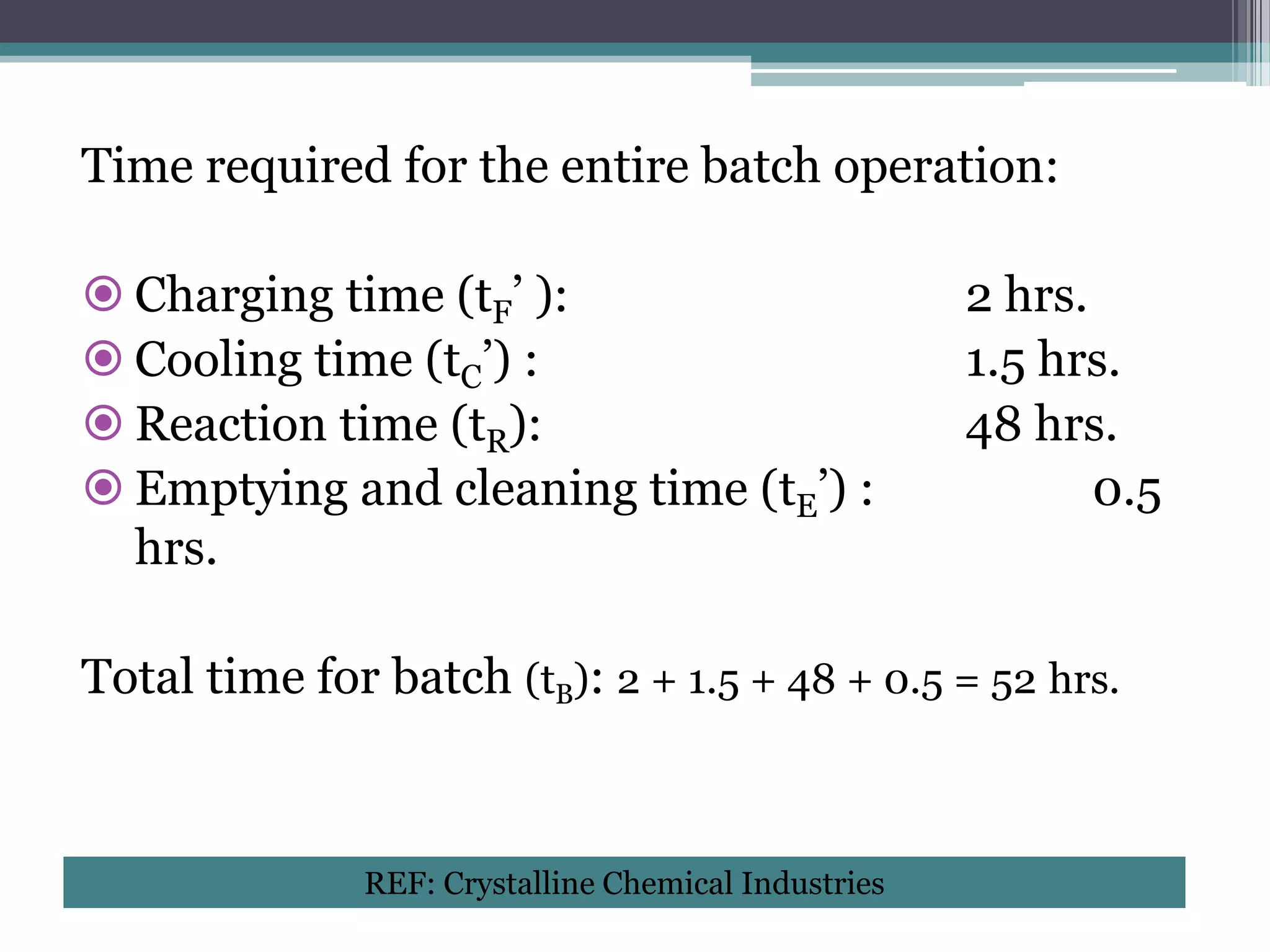
Time required forthe entire batch operation:
Charging time (tF’ ): 2 hrs.
Cooling time (tC’) : 1.5 hrs.
Reaction time (tR): 48 hrs.
Emptying and cleaning time (tE’) : 0.5
hrs.
Total time for batch (tB): 2 + 1.5 + 48 + 0.5 = 52 hrs.
REF: Crystalline Chemical Industries
19.
PROCESS DESIGN
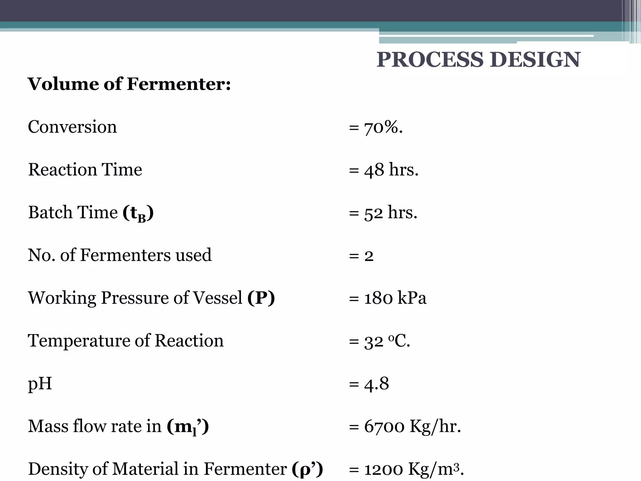
Volume ofFermenter:
Conversion = 70%.
Reaction Time = 48 hrs.
Batch Time (tB) = 52 hrs.
No. of Fermenters used =2
Working Pressure of Vessel (P) = 180 kPa
Temperature of Reaction = 32 oC.
pH = 4.8
Mass flow rate in (ml’) = 6700 Kg/hr.
Density of Material in Fermenter (ρ’) = 1200 Kg/m3.
20.
VOLUME OF FERMENTER
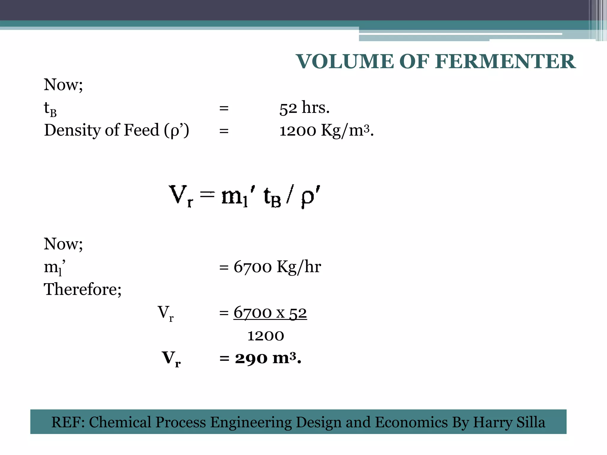
Now;
tB = 52 hrs.
Density of Feed (ρ’) = 1200 Kg/m3.
Now;
ml’ = 6700 Kg/hr
Therefore;
Vr = 6700 x 52
1200
Vr = 290 m3.
REF: Chemical Process Engineering Design and Economics By Harry Silla
21.
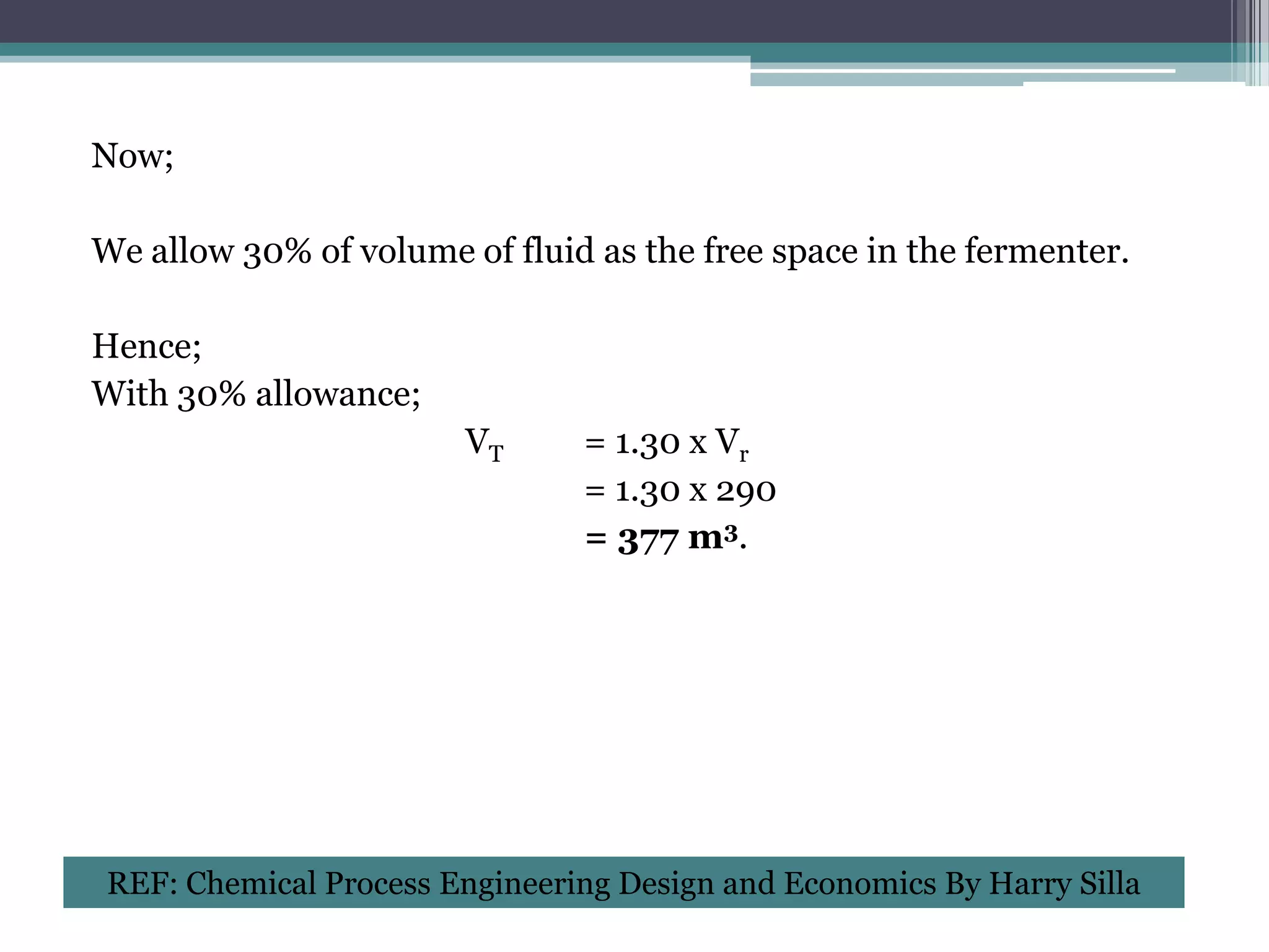
Now;
We allow 30%of volume of fluid as the free space in the fermenter.
Hence;
With 30% allowance;
VT = 1.30 x Vr
= 1.30 x 290
= 377 m3.
REF: Chemical Process Engineering Design and Economics By Harry Silla
22.
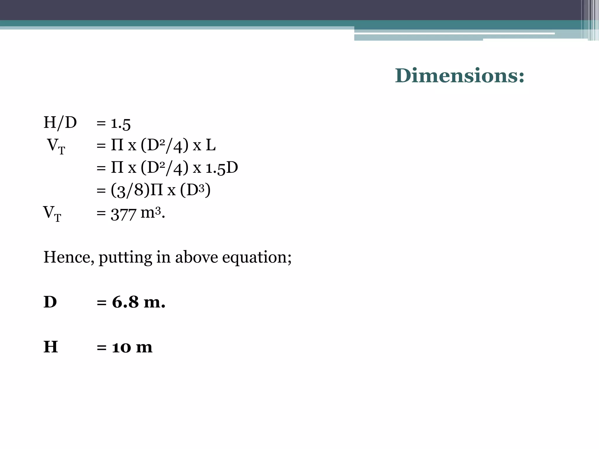
Dimensions:
H/D = 1.5
VT = Π x (D2/4) x L
= Π x (D2/4) x 1.5D
= (3/8)Π x (D3)
VT = 377 m3.
Hence, putting in above equation;
D = 6.8 m.
H = 10 m
23.
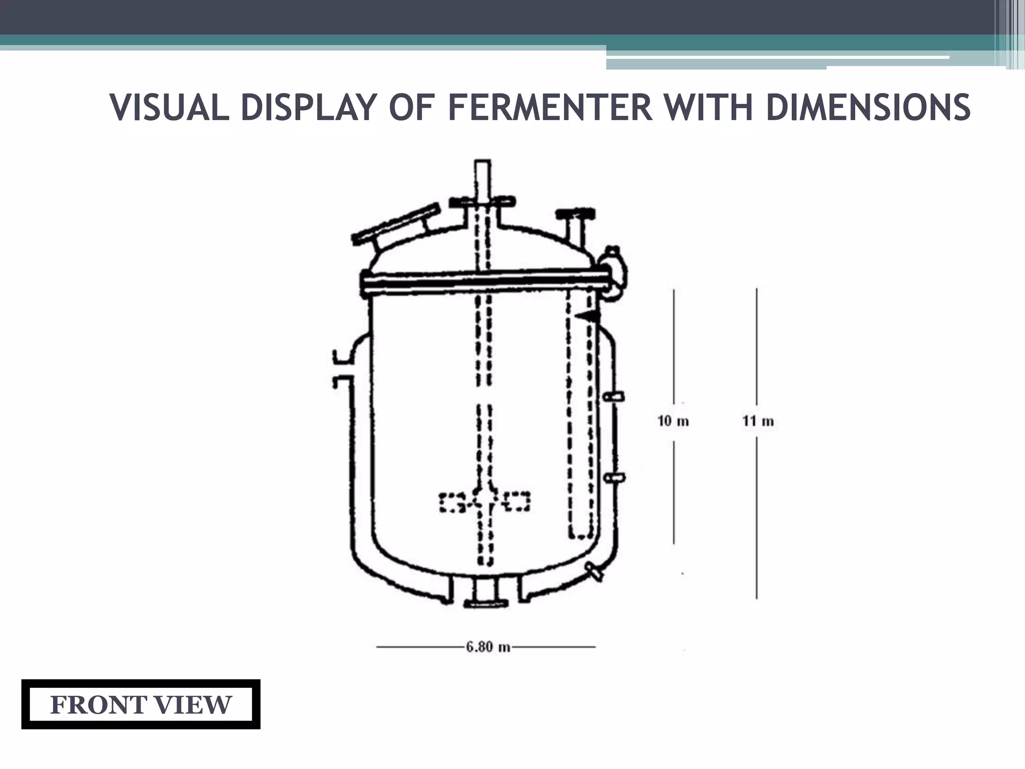
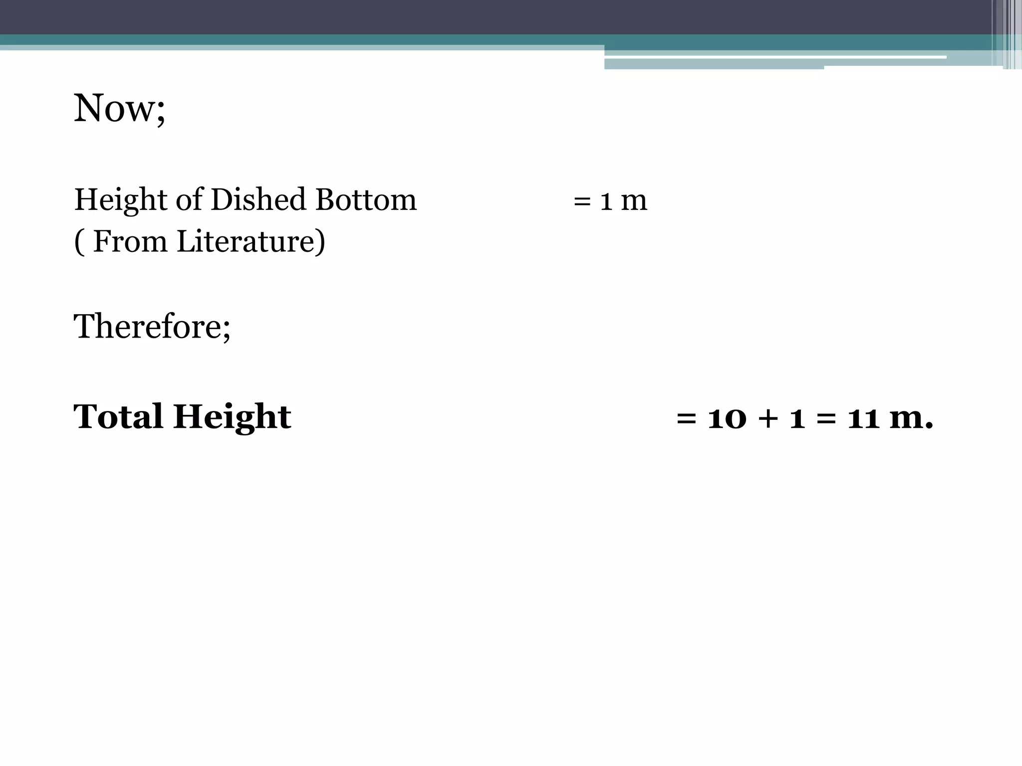
Now;
Height of DishedBottom =1m
( From Literature)
Therefore;
Total Height = 10 + 1 = 11 m.
25.
MECHANICAL DESIGN
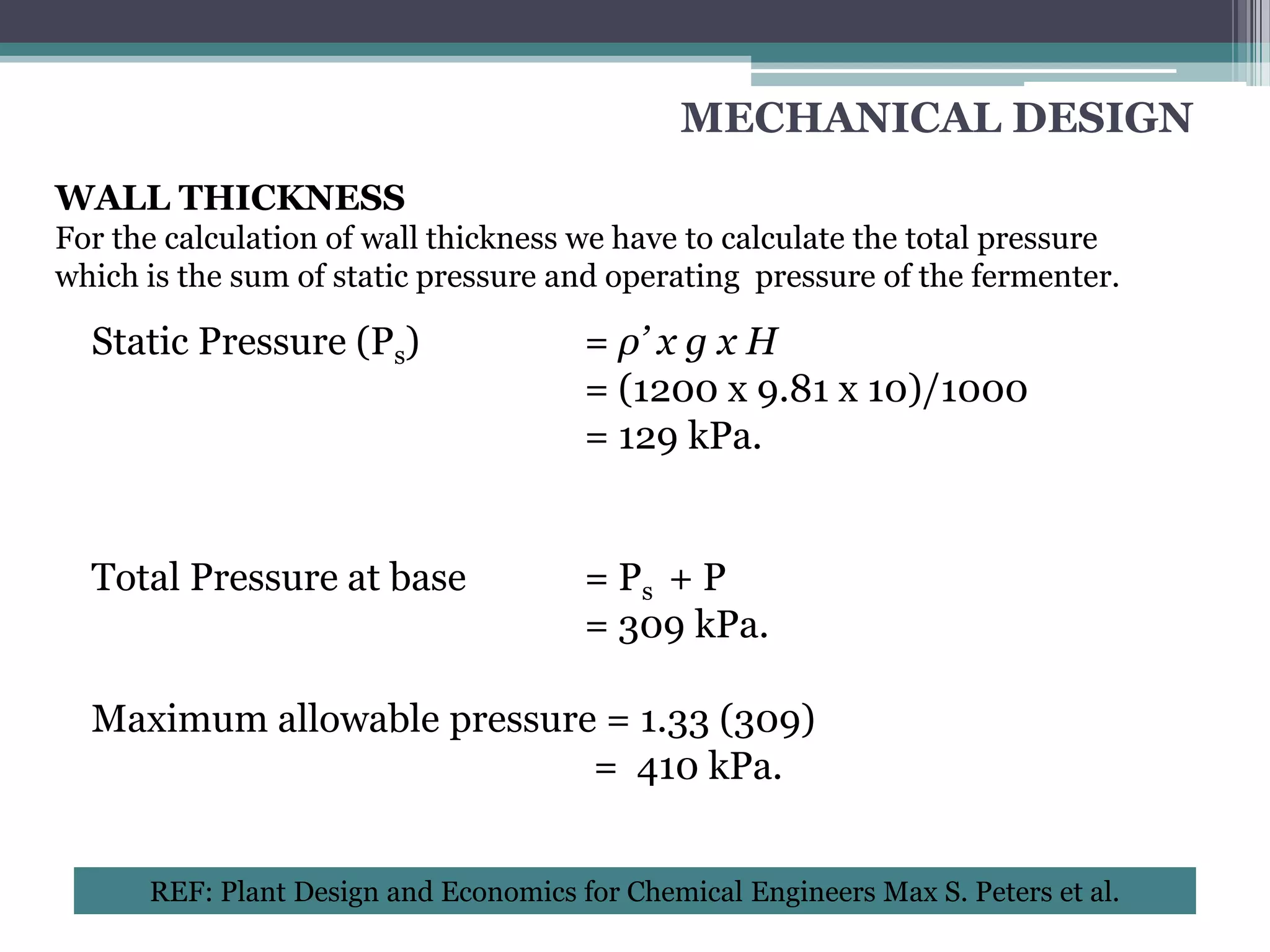
WALL THICKNESS
Forthe calculation of wall thickness we have to calculate the total pressure
which is the sum of static pressure and operating pressure of the fermenter.
Static Pressure (Ps) = ρ’ x g x H
= (1200 x 9.81 x 10)/1000
= 129 kPa.
Total Pressure at base = Ps + P
= 309 kPa.
Maximum allowable pressure = 1.33 (309)
= 410 kPa.
REF: Plant Design and Economics for Chemical Engineers Max S. Peters et al.
26.
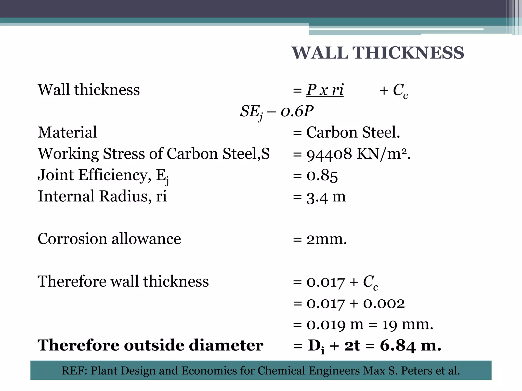
WALL THICKNESS
Wall thickness = P x ri + Cc
SEj – 0.6P
Material = Carbon Steel.
Working Stress of Carbon Steel,S = 94408 KN/m2.
Joint Efficiency, Ej = 0.85
Internal Radius, ri = 3.4 m
Corrosion allowance = 2mm.
Therefore wall thickness = 0.017 + Cc
= 0.017 + 0.002
= 0.019 m = 19 mm.
Therefore outside diameter = Di + 2t = 6.84 m.
REF: Plant Design and Economics for Chemical Engineers Max S. Peters et al.
27.
REACTOR HEAD
There arethree types of heads:
•Ellipsoidal Head.
•Torispherical Head.
•Hemispherical Head.
Ellipsoidal head is used for pressure greater than 150 psi and for less
than that pressure we use Torispherical head. That is why we have
selected a Torispherical head.
REF: Chemical Process Engineering Design and Economics By Harry Silla
REF: Coulson & Richard Chemical Engineering, Vol 6.
28.
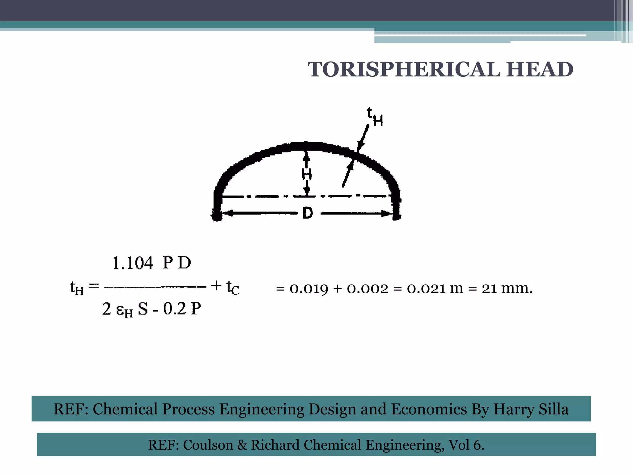
TORISPHERICAL HEAD
= 0.019 + 0.002 = 0.021 m = 21 mm.
REF: Chemical Process Engineering Design and Economics By Harry Silla
REF: Coulson & Richard Chemical Engineering, Vol 6.
29.
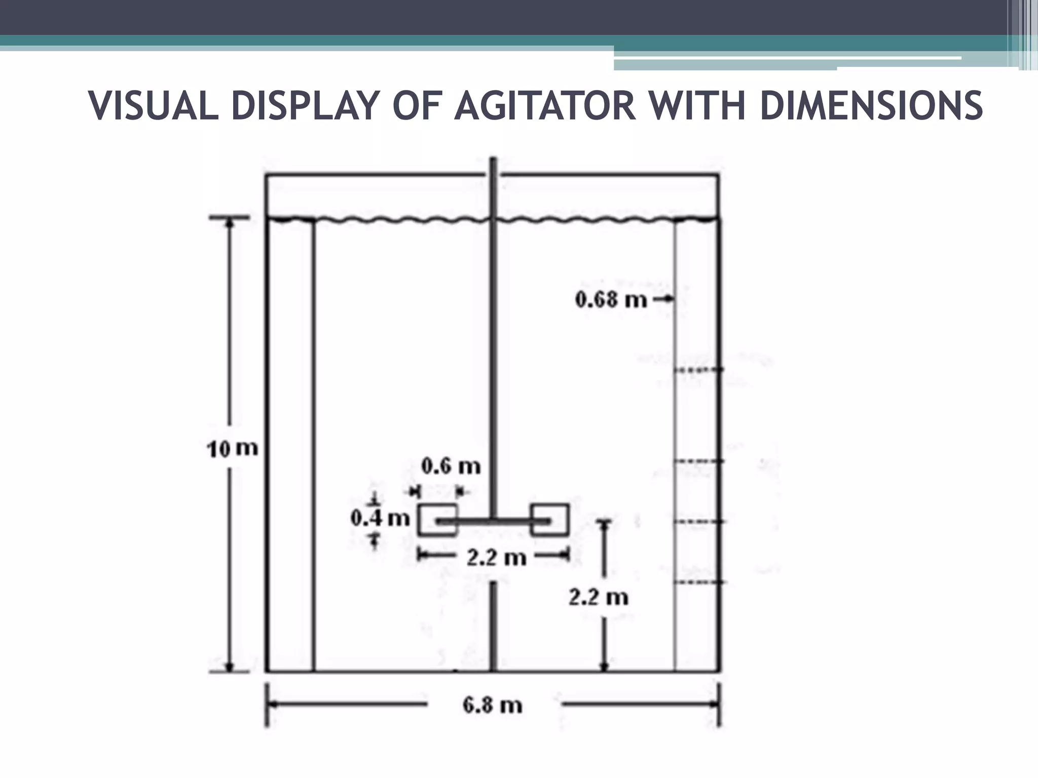
MECHANICAL DESIGN
AGITATORDESIGN
Agitator Dimensions are:
Impeller Diameter Da = Dt/3 = 2.2 m
Impeller Height above Vessel floor E = Da = 2.2 m
Length of Impeller Blade L = Da /4 = 0.6 m
Width of Impeller Blade W = Da /5 = 0.4 m
Width of Baffle J = Dt/10 = 0.68 m
No. of Impellers =3
No. of Impeller blades =6
Distance between 2 consecutive impellers = 2.2 m
Shape Factors are
S1 = Da/Dt = 1/3 S2 = E/Dt = 1/3
S3 = L/Da = 0.27 S4 = W/Da = 1/5
S5 = J/Dt = 1/10 S6 = H/Dt = 1.5
Tip Velocity = 3 – 6 m/sec
Tip Velocity = 5 m/sec
Tip Velocity = π x Da x N
Speed of Impeller = N = [5/( π x 2.2)] x 60 = 44 RPM
REF: Heuristics in Chemical Engineering Edited for On-Line Use by G. J. Suppes, 2002
REF: Unit Processes in Chemical Engineering By Mccabe, Smith & Harriot
30.
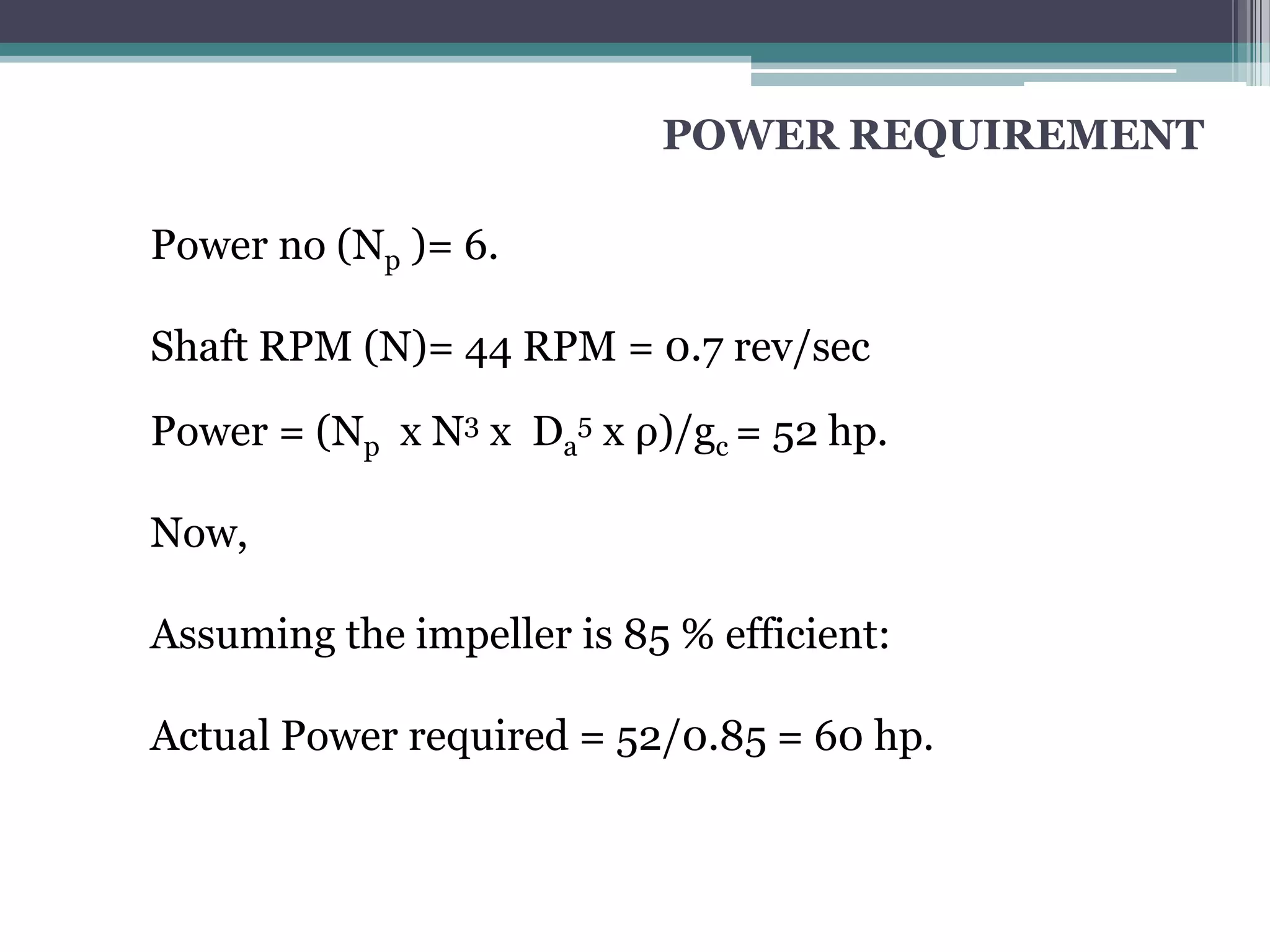
POWER REQUIREMENT
Power no(Np )= 6.
Shaft RPM (N)= 44 RPM = 0.7 rev/sec
Power = (Np x N3 x Da5 x ρ)/gc = 52 hp.
Now,
Assuming the impeller is 85 % efficient:
Actual Power required = 52/0.85 = 60 hp.
31.
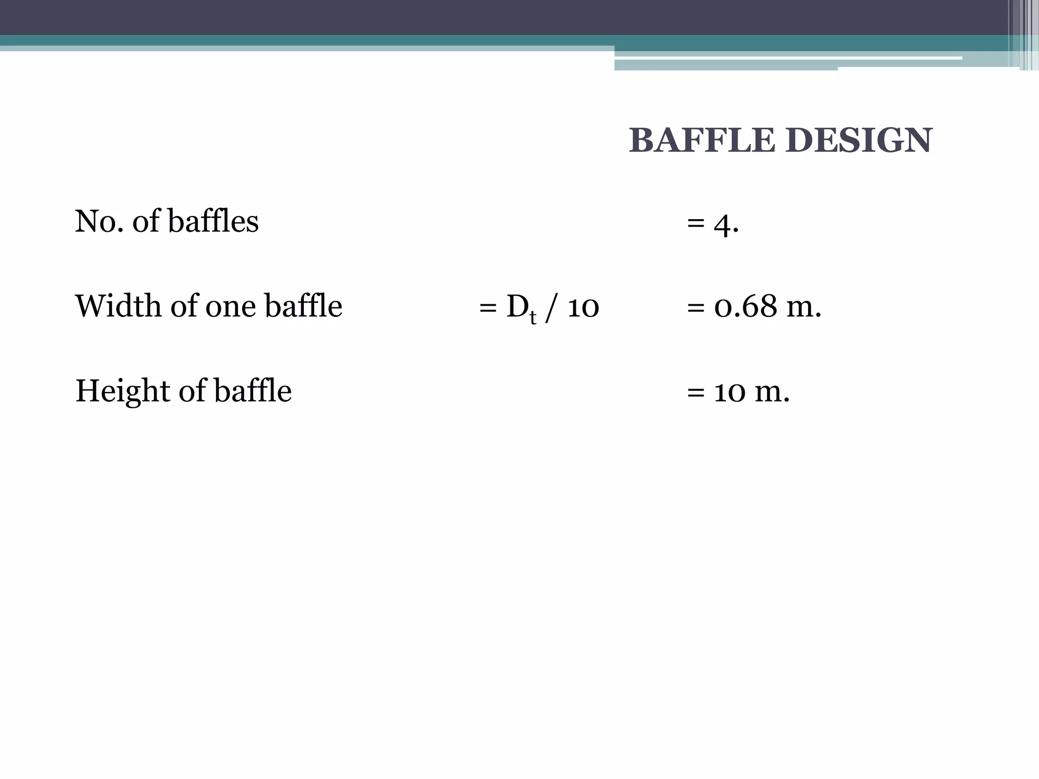
BAFFLE DESIGN
No. ofbaffles = 4.
Width of one baffle = Dt / 10 = 0.68 m.
Height of baffle = 10 m.
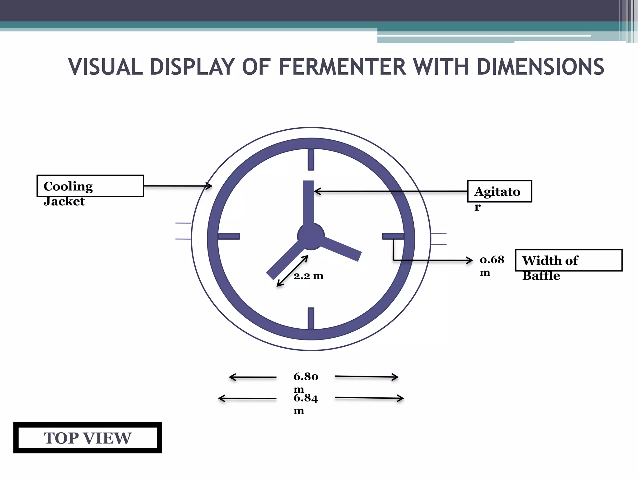
VISUAL DISPLAY OFFERMENTER WITH DIMENSIONS
Cooling Agitato
Jacket r
0.68 Width of
2.2 m m Baffle
6.80
m
6.84
m
TOP VIEW
35.
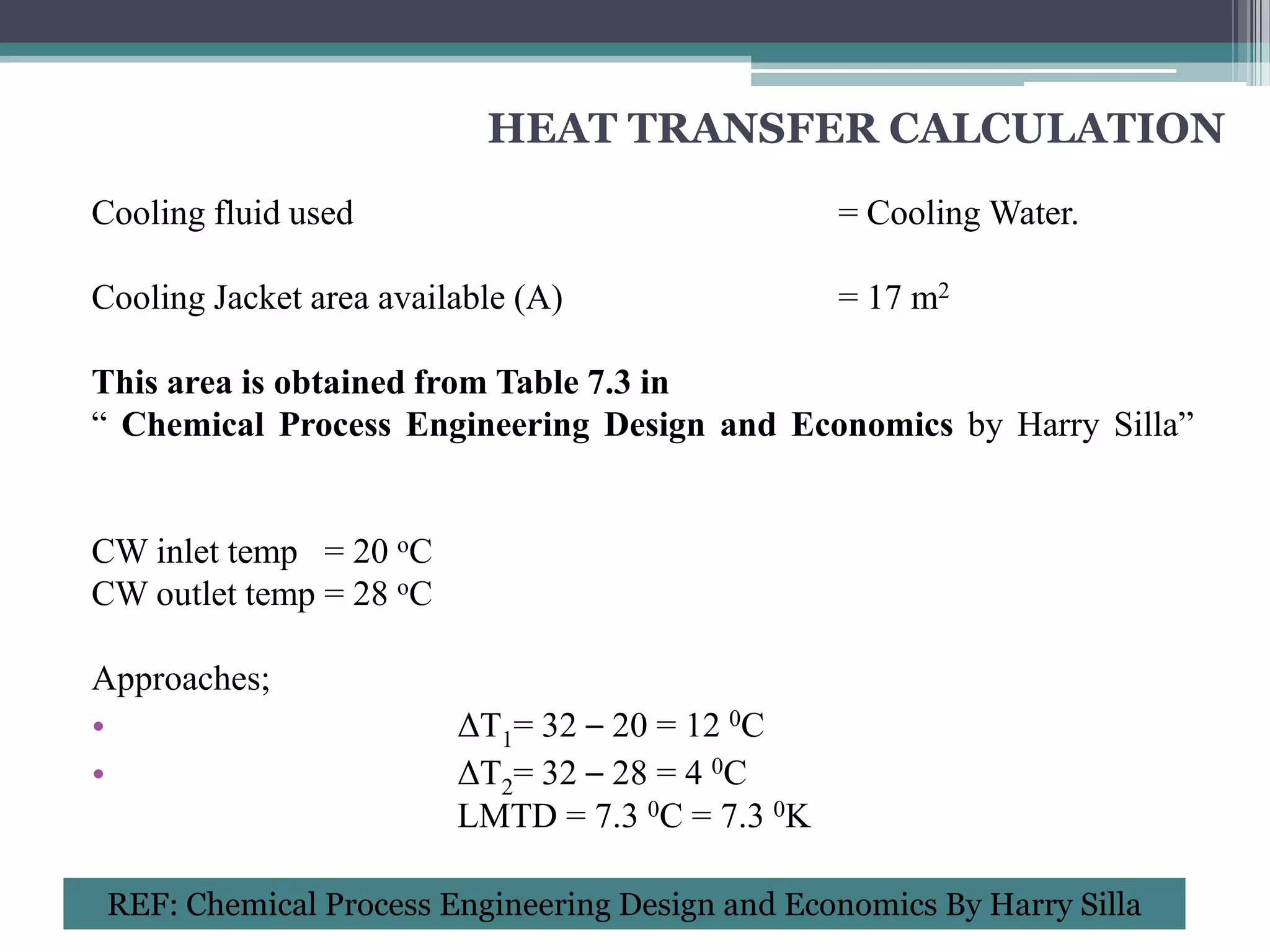
HEAT TRANSFER CALCULATION
Coolingfluid used = Cooling Water.
Cooling Jacket area available (A) = 17 m2
This area is obtained from Table 7.3 in
“ Chemical Process Engineering Design and Economics by Harry Silla”
CW inlet temp = 20 oC
CW outlet temp = 28 oC
Approaches;
• ΔT1= 32 – 20 = 12 0C
• ΔT2= 32 – 28 = 4 0C
LMTD = 7.3 0C = 7.3 0K
REF: Chemical Process Engineering Design and Economics By Harry Silla
36.
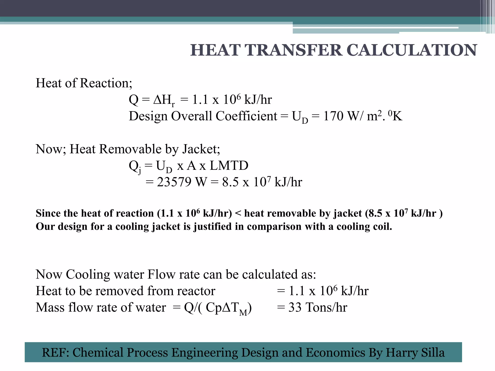
HEAT TRANSFER CALCULATION
Heatof Reaction;
Q = ∆Hr = 1.1 x 10⁶ kJ/hr
Design Overall Coefficient = UD = 170 W/ m2. 0K
Now; Heat Removable by Jacket;
Qj = UD x A x LMTD
= 23579 W = 8.5 x 10⁷ kJ/hr
Since the heat of reaction (1.1 x 10⁶ kJ/hr) < heat removable by jacket (8.5 x 10⁷ kJ/hr )
Our design for a cooling jacket is justified in comparison with a cooling coil.
Now Cooling water Flow rate can be calculated as:
Heat to be removed from reactor = 1.1 x 10⁶ kJ/hr
Mass flow rate of water = Q/( CpΔTM) = 33 Tons/hr
REF: Chemical Process Engineering Design and Economics By Harry Silla
38.
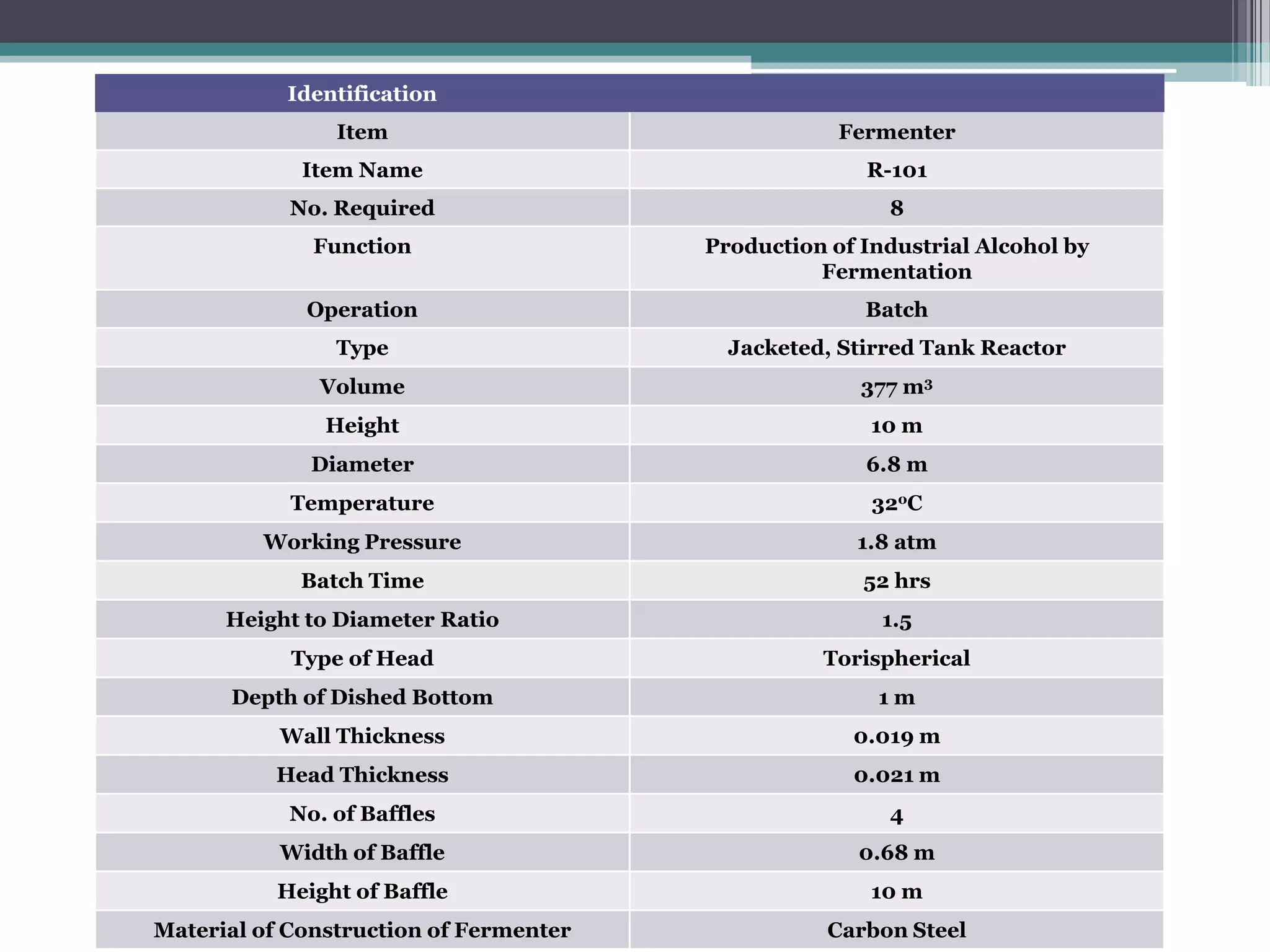
Identification
Item Fermenter
Item Name R-101
No. Required 8
Function Production of Industrial Alcohol by
Fermentation
Operation Batch
Type Jacketed, Stirred Tank Reactor
Volume 377 m3
Height 10 m
Diameter 6.8 m
Temperature 32oC
Working Pressure 1.8 atm
Batch Time 52 hrs
Height to Diameter Ratio 1.5
Type of Head Torispherical
Depth of Dished Bottom 1m
Wall Thickness 0.019 m
Head Thickness 0.021 m
No. of Baffles 4
Width of Baffle 0.68 m
Height of Baffle 10 m
Material of Construction of Fermenter Carbon Steel
39.
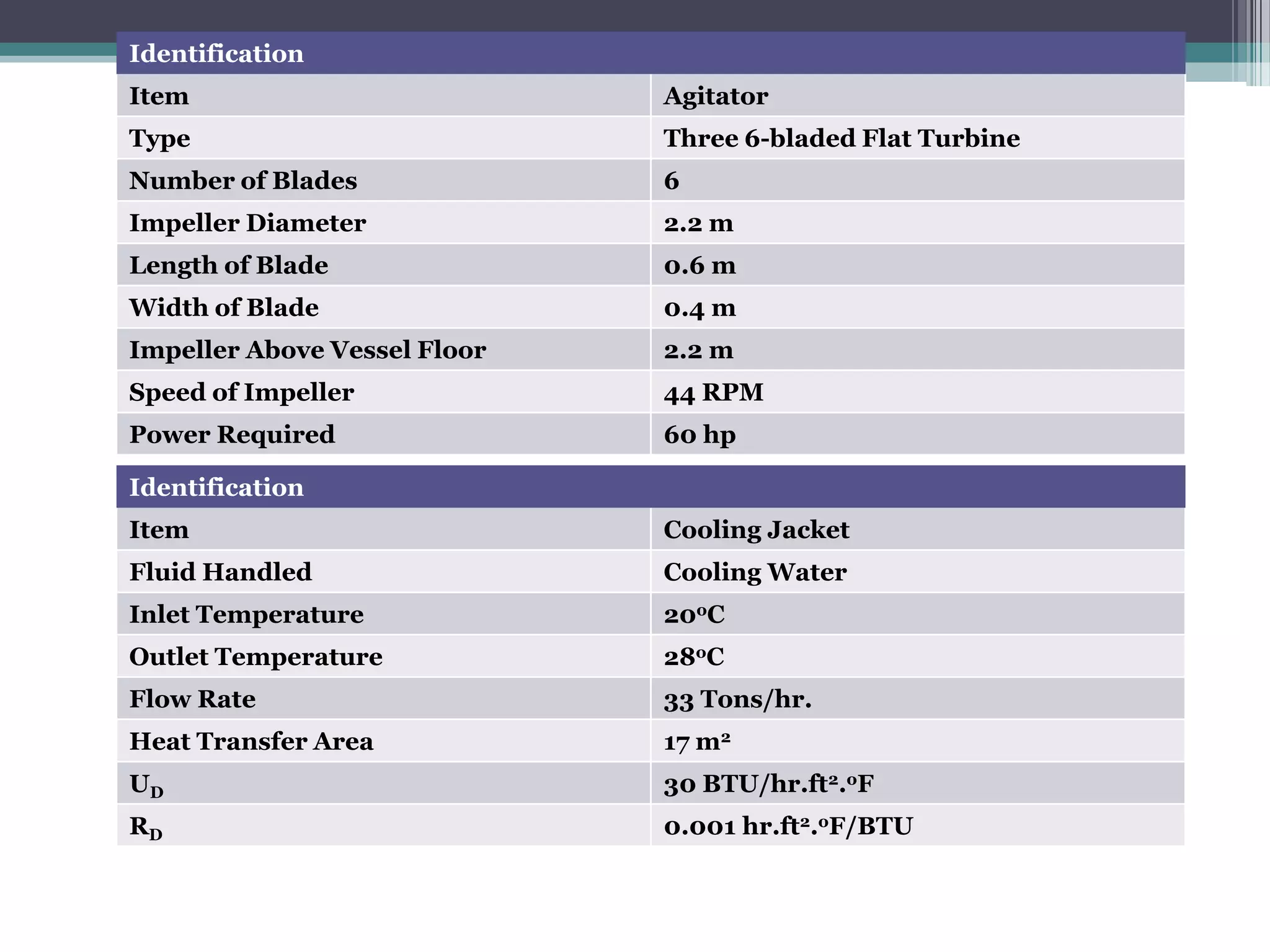
Identification
Item Agitator
Type Three 6-bladed Flat Turbine
Number of Blades 6
Impeller Diameter 2.2 m
Length of Blade 0.6 m
Width of Blade 0.4 m
Impeller Above Vessel Floor 2.2 m
Speed of Impeller 44 RPM
Power Required 60 hp
Identification
Item Cooling Jacket
Fluid Handled Cooling Water
Inlet Temperature 20oC
Outlet Temperature 28oC
Flow Rate 33 Tons/hr.
Heat Transfer Area 17 m2
UD 30 BTU/hr.ft2.oF
RD 0.001 hr.ft2.oF/BTU
Editor's Notes
#7 (e.g. a continuous stirred-tank reactor model). An example of a continuous bioreactor is the chemostat


![MECHANICAL DESIGN
AGITATOR DESIGN
Agitator Dimensions are:
Impeller Diameter Da = Dt/3 = 2.2 m
Impeller Height above Vessel floor E = Da = 2.2 m
Length of Impeller Blade L = Da /4 = 0.6 m
Width of Impeller Blade W = Da /5 = 0.4 m
Width of Baffle J = Dt/10 = 0.68 m
No. of Impellers =3
No. of Impeller blades =6
Distance between 2 consecutive impellers = 2.2 m
Shape Factors are
S1 = Da/Dt = 1/3 S2 = E/Dt = 1/3
S3 = L/Da = 0.27 S4 = W/Da = 1/5
S5 = J/Dt = 1/10 S6 = H/Dt = 1.5
Tip Velocity = 3 – 6 m/sec
Tip Velocity = 5 m/sec
Tip Velocity = π x Da x N
Speed of Impeller = N = [5/( π x 2.2)] x 60 = 44 RPM
REF: Heuristics in Chemical Engineering Edited for On-Line Use by G. J. Suppes, 2002
REF: Unit Processes in Chemical Engineering By Mccabe, Smith & Harriot](https://image.slidesharecdn.com/designofstirredbatchreactor-120425231652-phpapp02/75/Design-of-stirred-batch-reactor-29-2048.jpg)