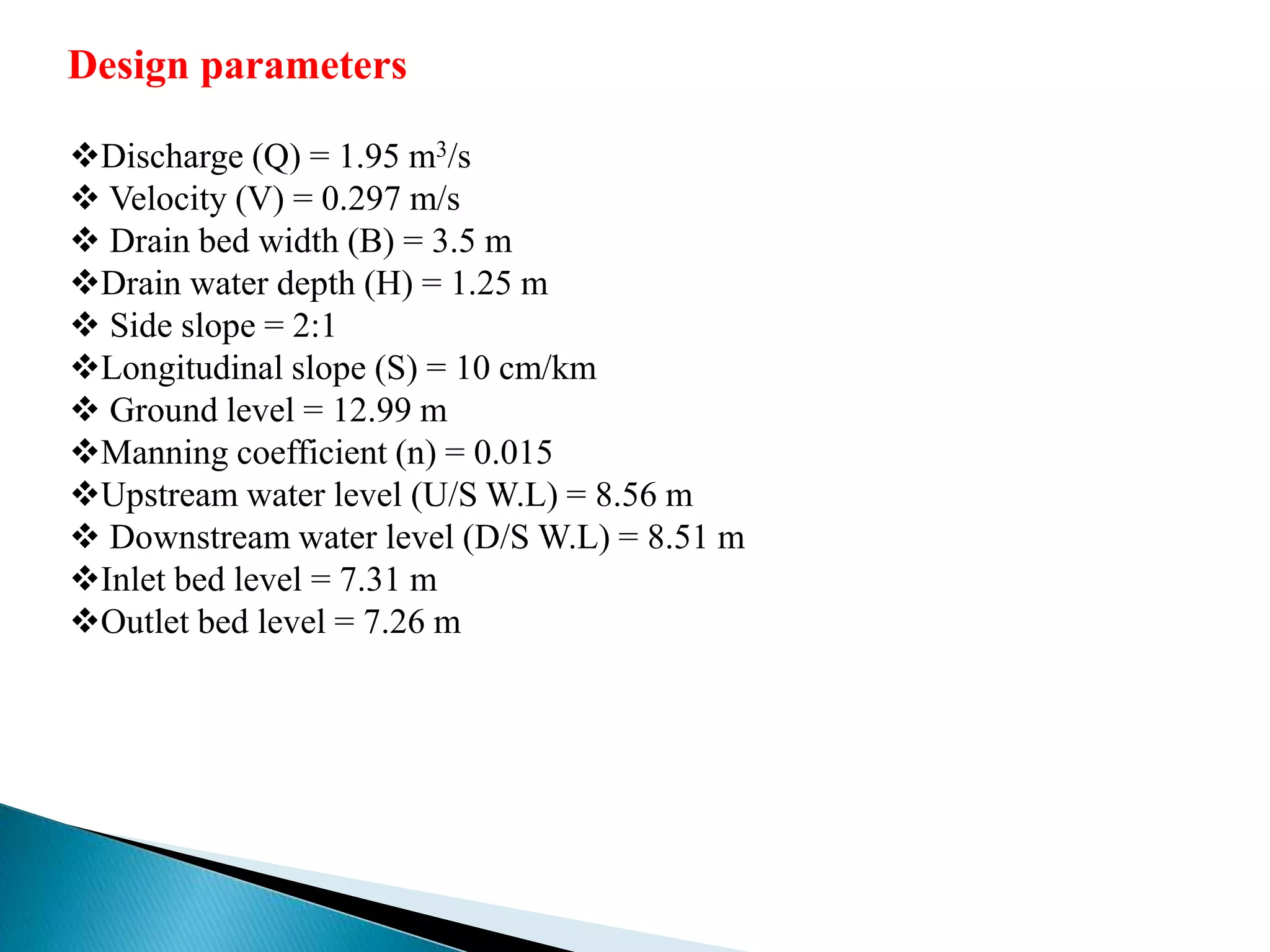
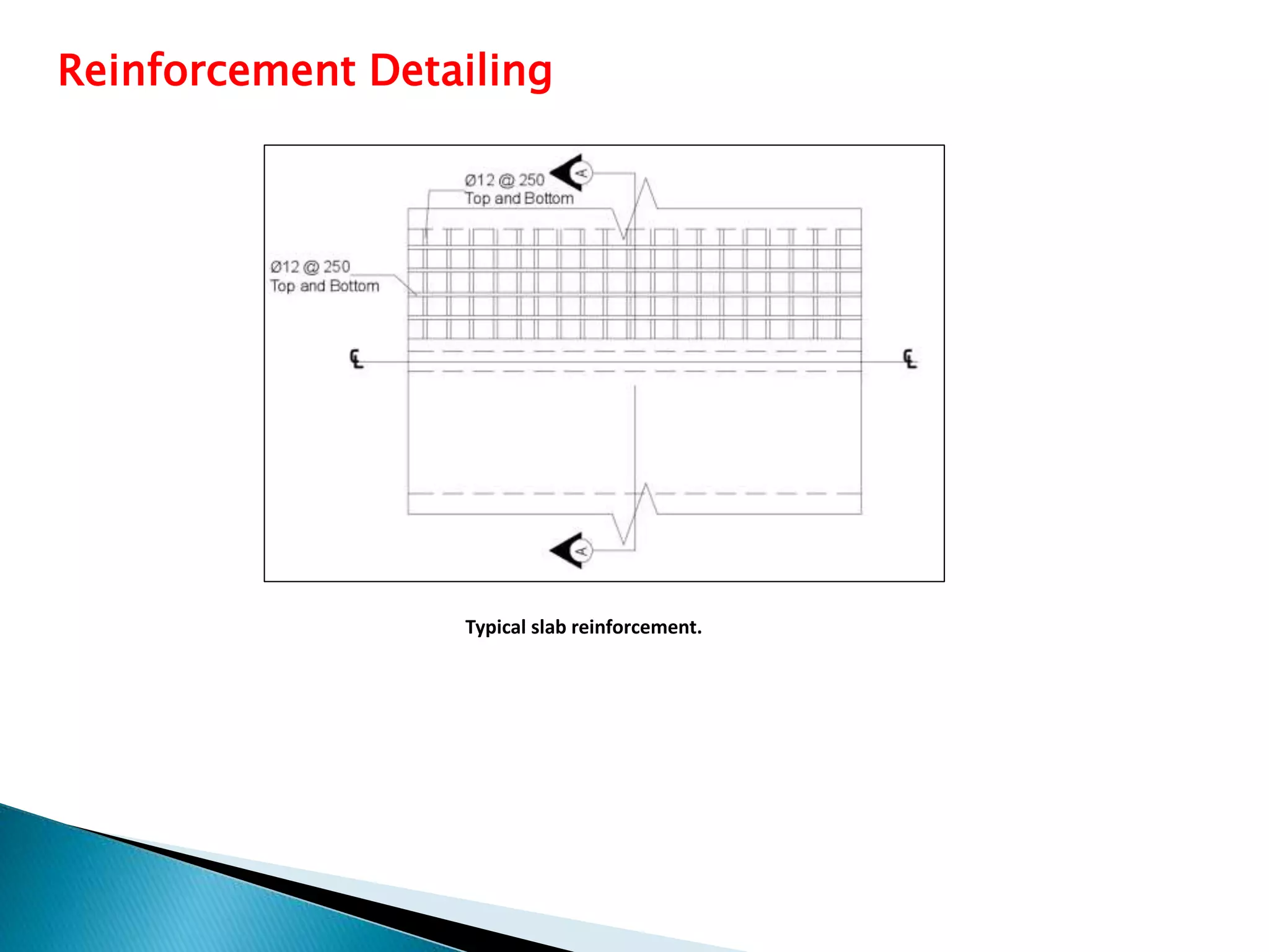
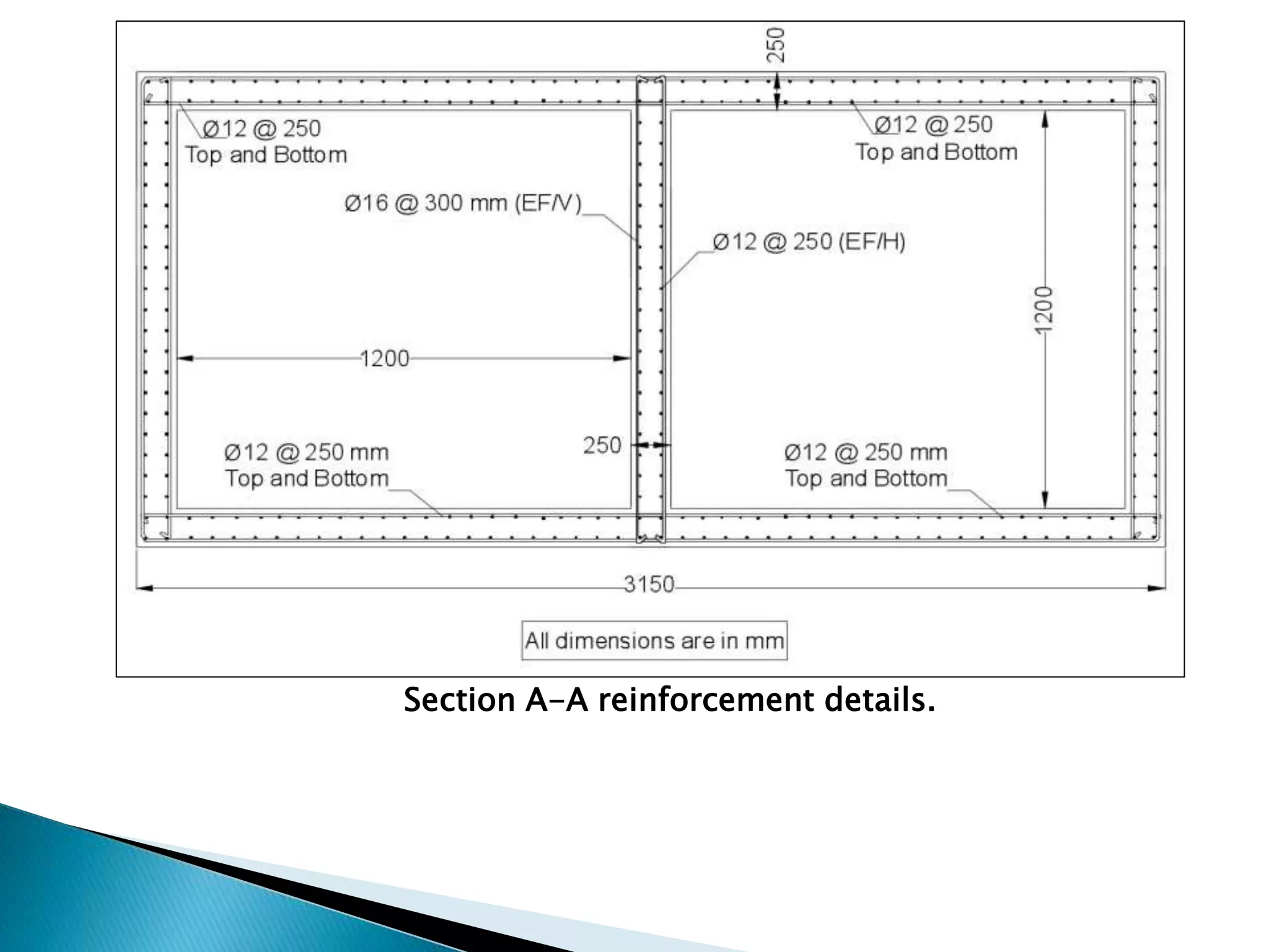
GURU NANAK
INSTITUTE OF TECHNOLOGY
A PRESENTATION
ON
ANALYSIS AND DESIGN OF RCC BOX CULVERT USING ETABS
DEPARTMENT OF CIVIL ENGINEERING
Under the guidance of
Mr. G.Janardhan
(Assistant Professor)
OVERVIEW
Abstract
Introduction
Objectives
Types of culvert
Design parameters
Reinforcement Detailing
Conclusion and Recommendation
References
Abstract
When it is required to construct a road that intersects with a natural stream flow or water
canal, the major problem shows as how to keep the stream flows without threatening the
roadway and the passing vehicles due to water rising when flooding at raining seasons or
overflow in the canal. For this purpose, a culvert must be constructed in the intersection. A
culvert is a structure designed to allow passing of water through.
The culverts are also required to balance the flood water on both side of earth embankment to
reduce the flood level on one side of road thereby decreasing the water head consequently
reducing the flood menace.
This paper deals with study of some of the design parameters of box culverts like angle of
dispersion or effective width of live load, effect of earth pressure and depth of cushion
provided on top slab of box culverts.
Introduction
Culvert is a hydraulic structure that allows water to flow under a road,railroad,
trail, or similar obstruction from one side to the other side.
A culvert may be a bridge-like structure designed to allow vehicle or
pedestrian traffic to cross over the waterway while allowing adequate passage
for the water.
Culverts are commonly used both as cross-drains for ditch relief and to pass
water under a road at natural drainage and stream crossings.
Culverts come in many sizes and shapes including round, elliptical, and box-
like constructions.
The structural design involves consideration of load cases (box empty, full,
surcharge loadsetc.) and factors like live load, effective width, braking force,
dispersal of load through fill,impactfactor, co-efficient of earth pressure etc.
Objectives
Determine the total loads acting on the various parts of the box culvert.
Suitable structure design for the box culvert.
Design reinforcement steel for the culvert.
Analysis the structurally designed box culvert using ETABS software.
Conceptualization of entire Project.
Types of Culvert
1. Pipe Culvert (Single or Multiple)
2. Pipe Arch Culvert (Single or Multiple)
3. Box Culvert (Single or Multiple)
4. Arch Culvert
5.Bridge Culvert
Pipe Culvert (Single or Multiple) Pipe Arch Culvert (Single or Multiple)
Box Culvert (Single or Multiple)
Arch Culvert Bridge Culvert
Design parameters
Discharge (Q) = 1.95 m3/s
 Velocity (V) = 0.297 m/s
 Drain bed width (B) = 3.5 m
Drain water depth (H) = 1.25 m
 Side slope = 2:1
Longitudinal slope (S) = 10 cm/km
 Ground level = 12.99 m
Manning coefficient (n) = 0.015
Upstream water level (U/S W.L) = 8.56 m
 Downstream water level (D/S W.L) = 8.51 m
Inlet bed level = 7.31 m
Outlet bed level = 7.26 m
Reinforcement Detailing
Typical slab reinforcement.
Section A-A reinforcement details.
Advantages and Disadvantages
ADVANTAGES OF CULVERTS:
Curverts prevent erosion.
 It prevent floods.
Aslo, do not allow water to overflow.
Divert water for farming/engineering purposes.
DISADVANTAGES OF CULVERTS:
If poorly shaped, aquatic organisms may be prohibited from growing
between upstream and downstream habitats.
If designed or installed incorrectly, severe scouring and corrosion can
occur.
Conclusion and recommendation
The dimensions of box culvert were obtained from the hydraulic design.
The box culvert designed as a two cells culvert with a total length of 27 m
and total width of 3.15 m. The span for each cell is 1.2 m measured from
face of the supports. The invert of the box culvert is 0.2m downward from
the bottom of the main drain (MD-A). Conveyance condition case 4 gave
the minimum head losses as required.
The box culvert structural elements are top slab, floor slab, two exterior
side walls and one interior wall. The box culvert structural design carried
out for the maximum bending moment and shear force in each structural
element. The design was analyzed by ETABS software which gave a
resemble results to the hand calculated results. The used reinforcements are:
𝑚𝑚 𝐶*𝐶(𝐸𝐹⁄𝑉) 𝑚𝑚 𝐶*𝐶(𝐸𝐹⁄𝐻) for the walls.
𝑚𝑚 𝐶*𝐶 𝑎𝑡 𝑡𝑜𝑝 𝑎𝑛𝑑 𝑏𝑜𝑡𝑡𝑜𝑚 for top and
floor slabs.
References
Garg, A. K., (2007). “Experimental and Finite Element Based Investigations of
Shear Behavior of Reinforced Concrete Box Culverts”, PhD Dissertation, Department of Civil
Engineering, The University of Texas at Arlington.
Kailan, A. L. (2015). “Hydraulic structures”, Water Resources Engineering lectures, Chapter 5,
Department of Civil Engineering, Al-Mansour University College, Iraq.
Kilgore, R. T., Morris, J. L., Schall, J. D., Thompson, P. L. and Zerges, S. M. (2012).
“Hydraulic Design of Highway Culverts Third Edition”. Federal Highway Administration
(FHWA), Washington, D.C. PP 326.
 Kumar, Y. V., Srinivas, C. (2015). “Analysis and Design of Box Culvert by Using
Computational Methods”, International Journal of Engineering and Science Research, 5(7): 850-
861.
Kim, K. and Yoo, C. (2002), “Design loading for deeply buried box culverts”, Highway Research
Center Auburn University, Auburn University, Alabama.
THANK YOU
Hareram yadav 17831A01C4
Satrudhan kr. Mukhiya 17831A01B5
Shiva kumar Singh 17831A01B7

DESIGN OF RCC CULVERT

  • 1.
    GURU NANAK INSTITUTE OFTECHNOLOGY A PRESENTATION ON ANALYSIS AND DESIGN OF RCC BOX CULVERT USING ETABS DEPARTMENT OF CIVIL ENGINEERING Under the guidance of Mr. G.Janardhan (Assistant Professor)
  • 2.
    OVERVIEW Abstract Introduction Objectives Types of culvert Designparameters Reinforcement Detailing Conclusion and Recommendation References
  • 3.
    Abstract When it isrequired to construct a road that intersects with a natural stream flow or water canal, the major problem shows as how to keep the stream flows without threatening the roadway and the passing vehicles due to water rising when flooding at raining seasons or overflow in the canal. For this purpose, a culvert must be constructed in the intersection. A culvert is a structure designed to allow passing of water through. The culverts are also required to balance the flood water on both side of earth embankment to reduce the flood level on one side of road thereby decreasing the water head consequently reducing the flood menace. This paper deals with study of some of the design parameters of box culverts like angle of dispersion or effective width of live load, effect of earth pressure and depth of cushion provided on top slab of box culverts.
  • 4.
    Introduction Culvert is ahydraulic structure that allows water to flow under a road,railroad, trail, or similar obstruction from one side to the other side. A culvert may be a bridge-like structure designed to allow vehicle or pedestrian traffic to cross over the waterway while allowing adequate passage for the water. Culverts are commonly used both as cross-drains for ditch relief and to pass water under a road at natural drainage and stream crossings. Culverts come in many sizes and shapes including round, elliptical, and box- like constructions. The structural design involves consideration of load cases (box empty, full, surcharge loadsetc.) and factors like live load, effective width, braking force, dispersal of load through fill,impactfactor, co-efficient of earth pressure etc.
  • 5.
    Objectives Determine the totalloads acting on the various parts of the box culvert. Suitable structure design for the box culvert. Design reinforcement steel for the culvert. Analysis the structurally designed box culvert using ETABS software. Conceptualization of entire Project.
  • 6.
    Types of Culvert 1.Pipe Culvert (Single or Multiple) 2. Pipe Arch Culvert (Single or Multiple) 3. Box Culvert (Single or Multiple) 4. Arch Culvert 5.Bridge Culvert Pipe Culvert (Single or Multiple) Pipe Arch Culvert (Single or Multiple)
  • 7.
    Box Culvert (Singleor Multiple) Arch Culvert Bridge Culvert
  • 8.
    Design parameters Discharge (Q)= 1.95 m3/s  Velocity (V) = 0.297 m/s  Drain bed width (B) = 3.5 m Drain water depth (H) = 1.25 m  Side slope = 2:1 Longitudinal slope (S) = 10 cm/km  Ground level = 12.99 m Manning coefficient (n) = 0.015 Upstream water level (U/S W.L) = 8.56 m  Downstream water level (D/S W.L) = 8.51 m Inlet bed level = 7.31 m Outlet bed level = 7.26 m
  • 9.
  • 10.
  • 11.
    Advantages and Disadvantages ADVANTAGESOF CULVERTS: Curverts prevent erosion.  It prevent floods. Aslo, do not allow water to overflow. Divert water for farming/engineering purposes. DISADVANTAGES OF CULVERTS: If poorly shaped, aquatic organisms may be prohibited from growing between upstream and downstream habitats. If designed or installed incorrectly, severe scouring and corrosion can occur.
  • 12.
    Conclusion and recommendation Thedimensions of box culvert were obtained from the hydraulic design. The box culvert designed as a two cells culvert with a total length of 27 m and total width of 3.15 m. The span for each cell is 1.2 m measured from face of the supports. The invert of the box culvert is 0.2m downward from the bottom of the main drain (MD-A). Conveyance condition case 4 gave the minimum head losses as required. The box culvert structural elements are top slab, floor slab, two exterior side walls and one interior wall. The box culvert structural design carried out for the maximum bending moment and shear force in each structural element. The design was analyzed by ETABS software which gave a resemble results to the hand calculated results. The used reinforcements are: 𝑚𝑚 𝐶*𝐶(𝐸𝐹⁄𝑉) 𝑚𝑚 𝐶*𝐶(𝐸𝐹⁄𝐻) for the walls. 𝑚𝑚 𝐶*𝐶 𝑎𝑡 𝑡𝑜𝑝 𝑎𝑛𝑑 𝑏𝑜𝑡𝑡𝑜𝑚 for top and floor slabs.
  • 13.
    References Garg, A. K.,(2007). “Experimental and Finite Element Based Investigations of Shear Behavior of Reinforced Concrete Box Culverts”, PhD Dissertation, Department of Civil Engineering, The University of Texas at Arlington. Kailan, A. L. (2015). “Hydraulic structures”, Water Resources Engineering lectures, Chapter 5, Department of Civil Engineering, Al-Mansour University College, Iraq. Kilgore, R. T., Morris, J. L., Schall, J. D., Thompson, P. L. and Zerges, S. M. (2012). “Hydraulic Design of Highway Culverts Third Edition”. Federal Highway Administration (FHWA), Washington, D.C. PP 326.  Kumar, Y. V., Srinivas, C. (2015). “Analysis and Design of Box Culvert by Using Computational Methods”, International Journal of Engineering and Science Research, 5(7): 850- 861. Kim, K. and Yoo, C. (2002), “Design loading for deeply buried box culverts”, Highway Research Center Auburn University, Auburn University, Alabama.
  • 14.
    THANK YOU Hareram yadav17831A01C4 Satrudhan kr. Mukhiya 17831A01B5 Shiva kumar Singh 17831A01B7