Downloaded 1,239 times


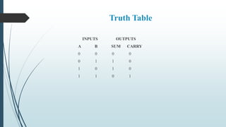
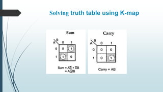

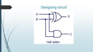


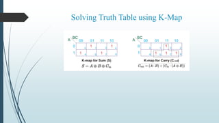

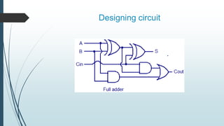
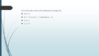

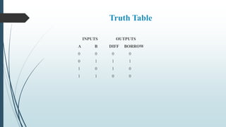
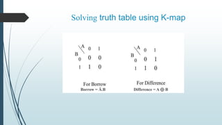

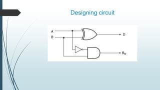

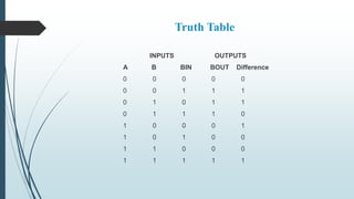
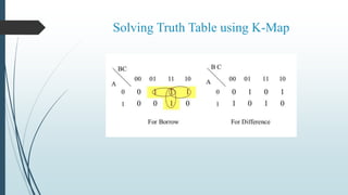


This document describes the design and operation of half adders, full adders, half subtractors, and full subtractors. It defines each component, provides their truth tables, and shows how to design the logic circuits using K-maps. Half adders and subtractors perform addition and subtraction of two single bits, while full adders and subtractors handle three input bits, accounting for values carried in and out. The document also distinguishes between the components and their uses in digital logic systems.