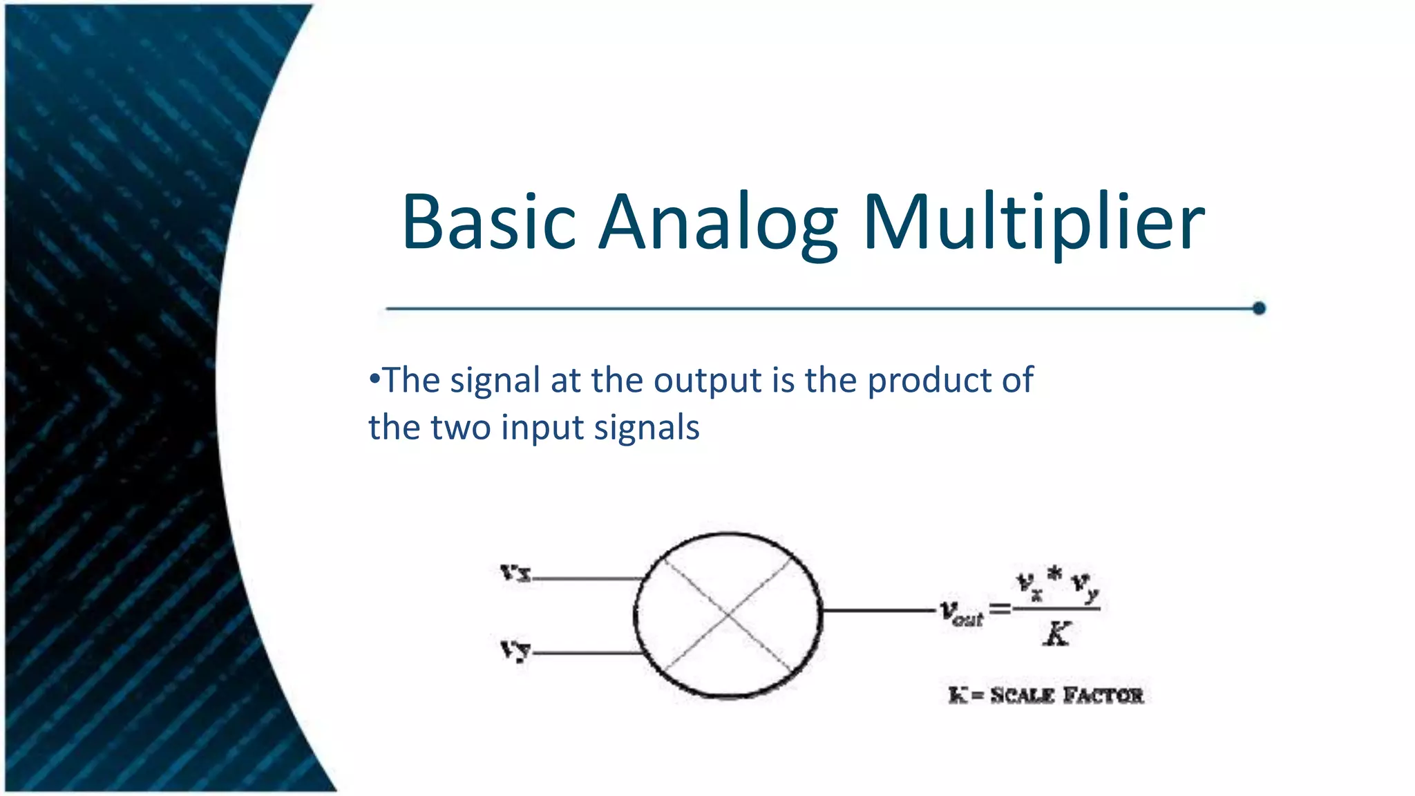
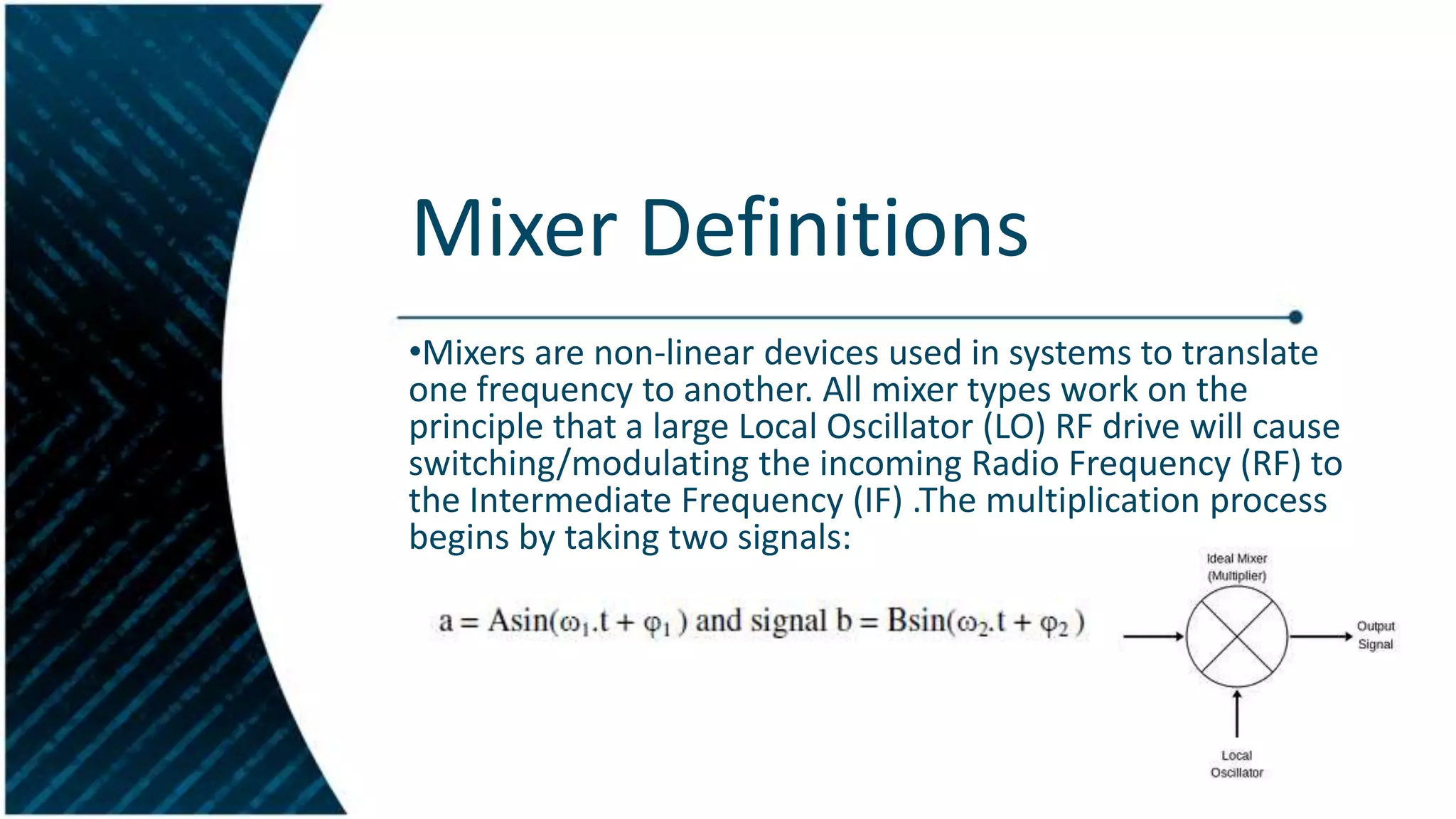
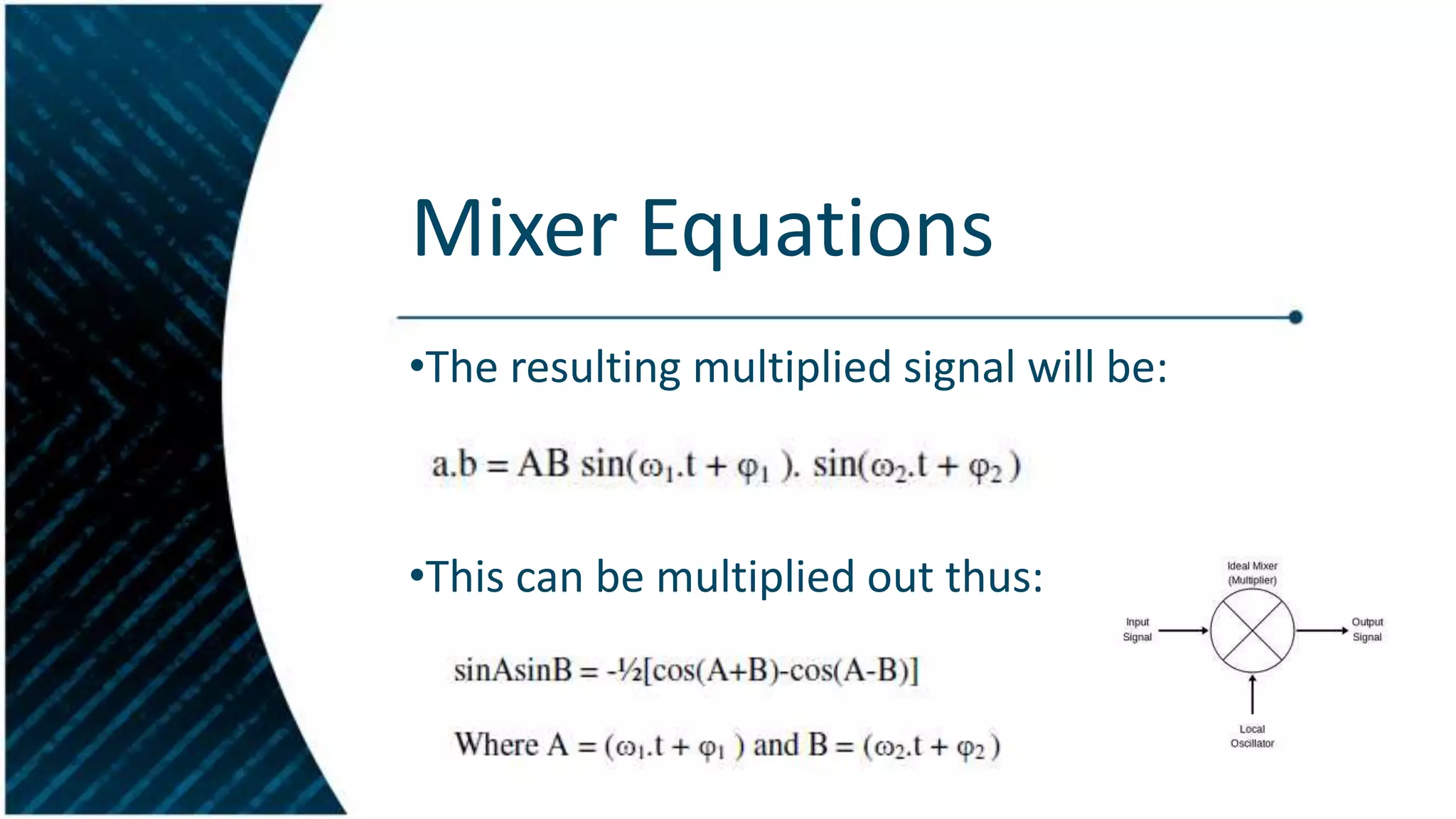
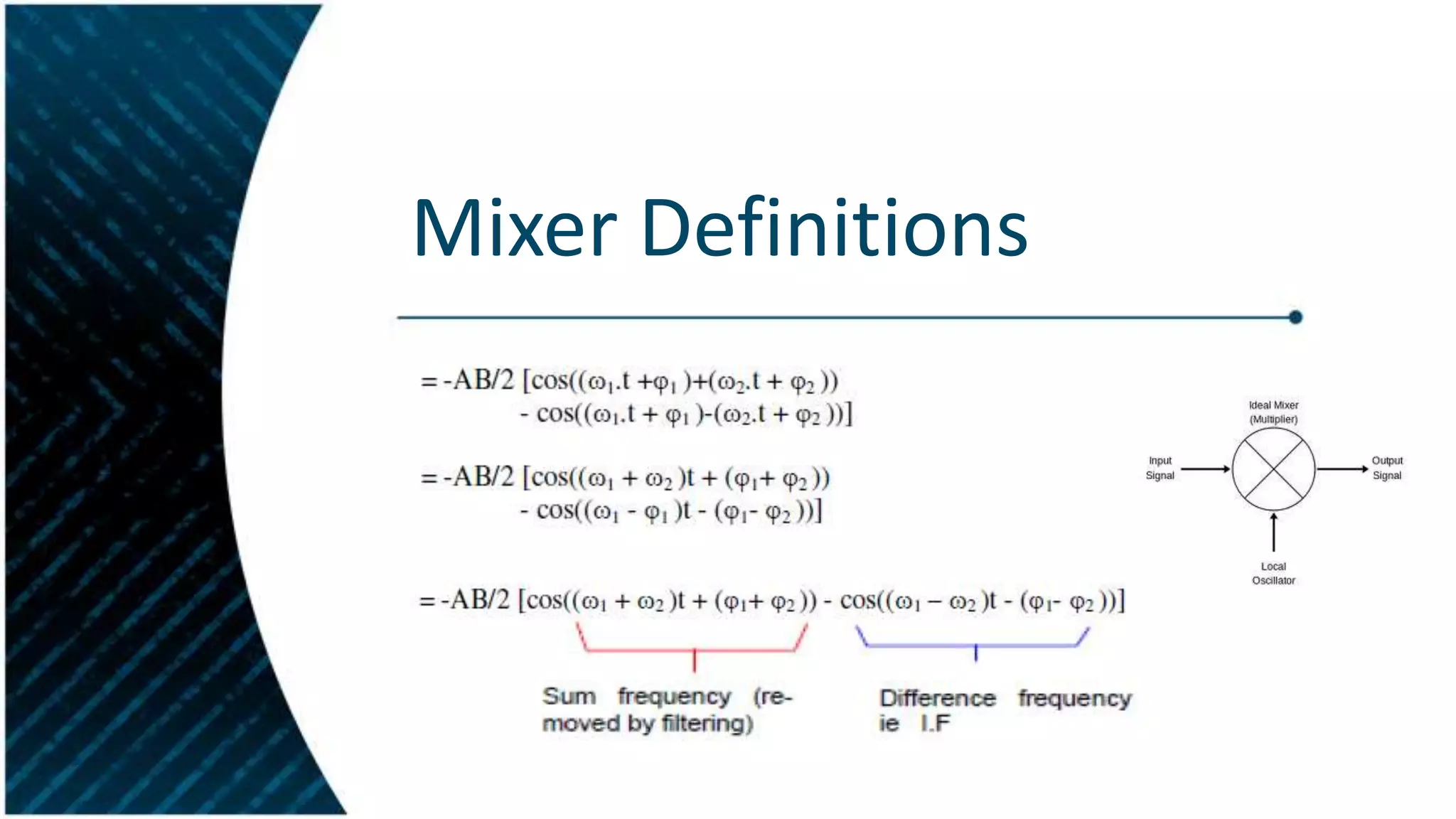
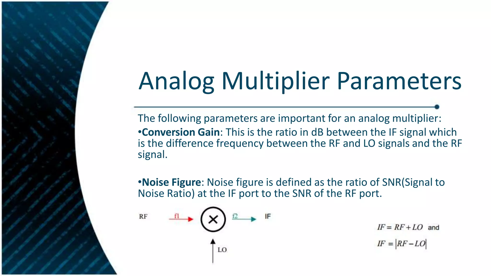
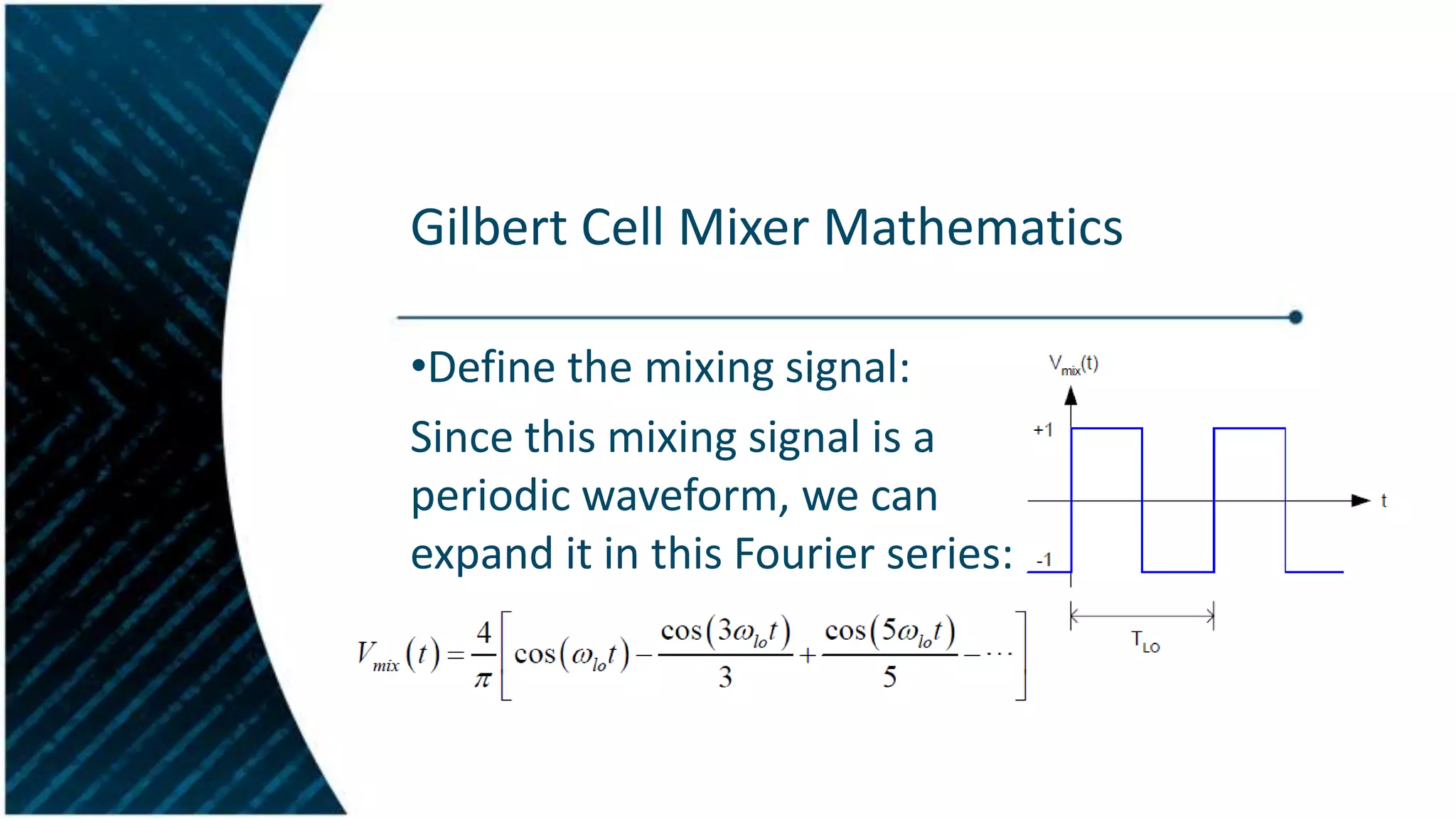
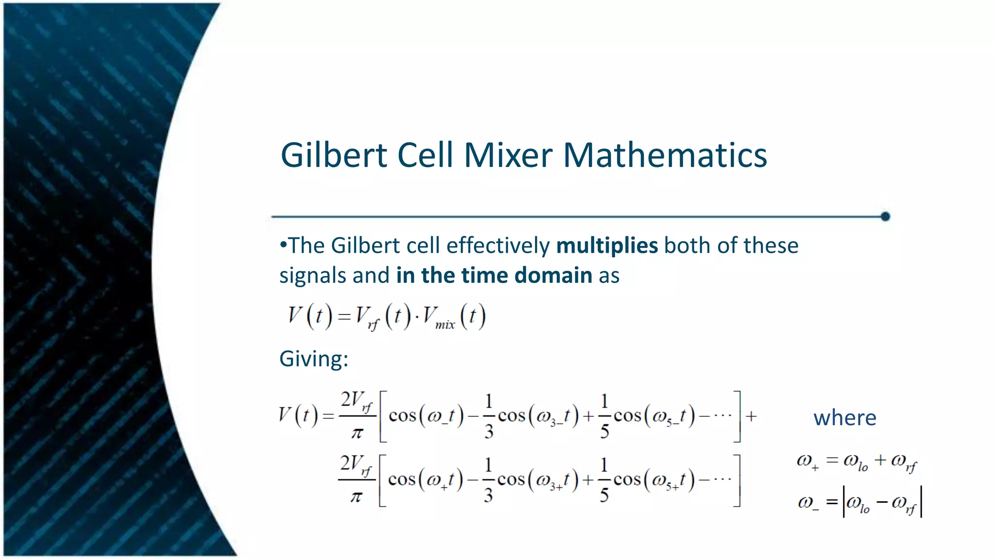
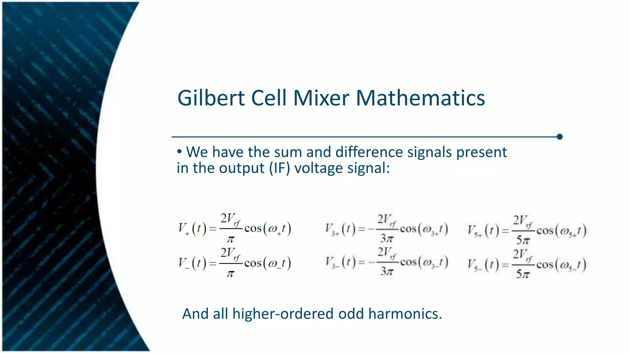
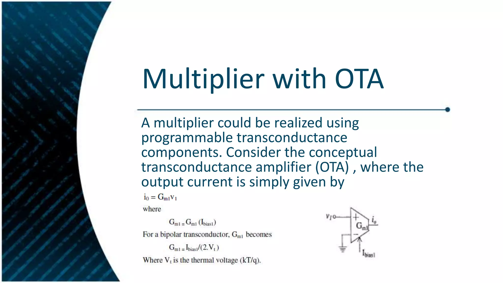
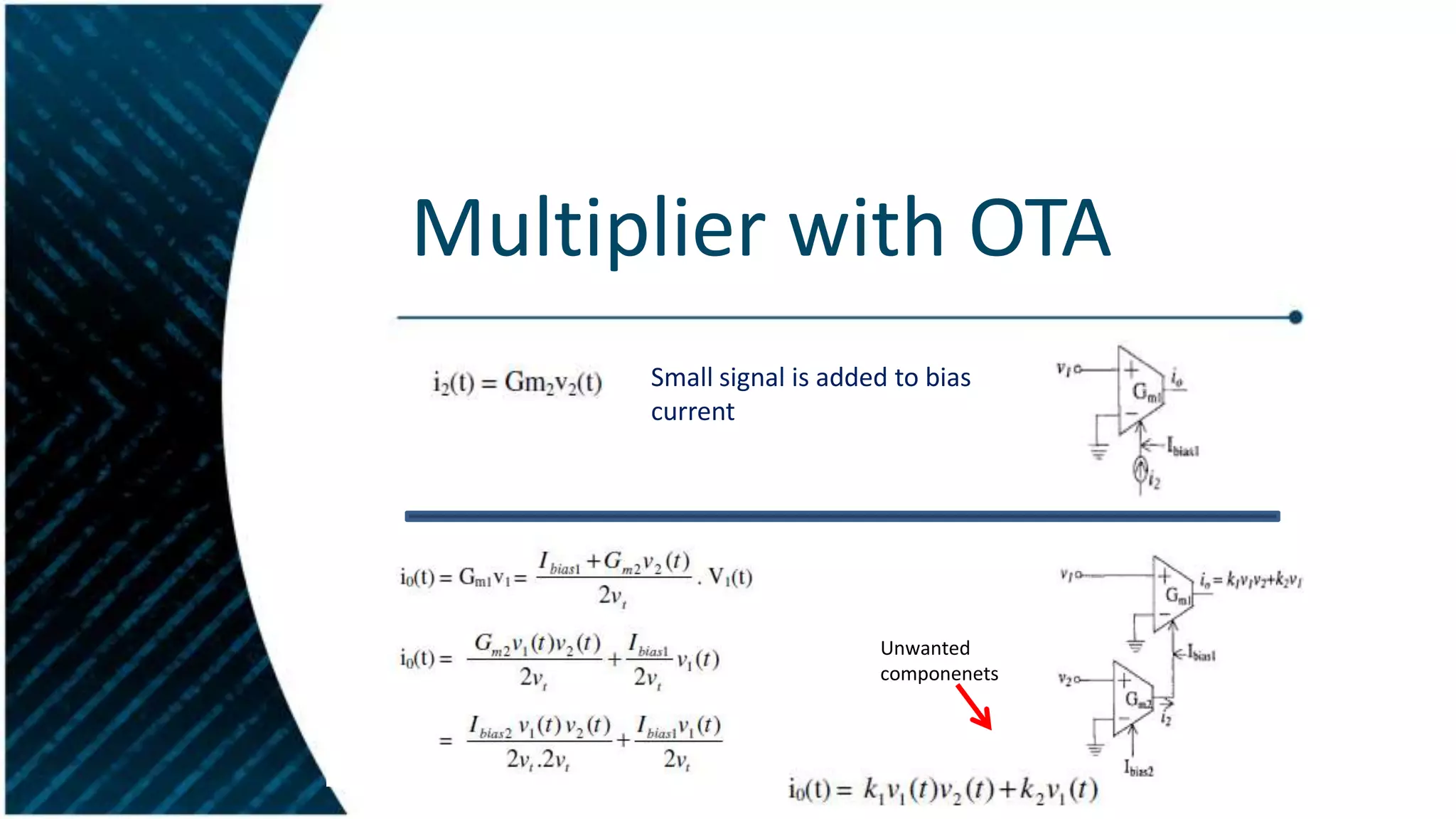
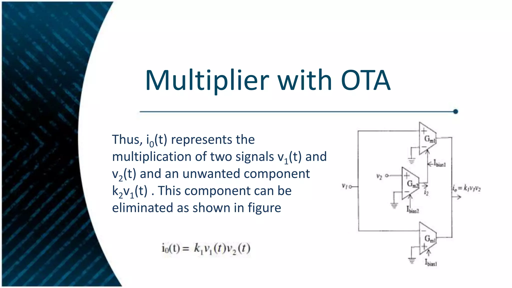
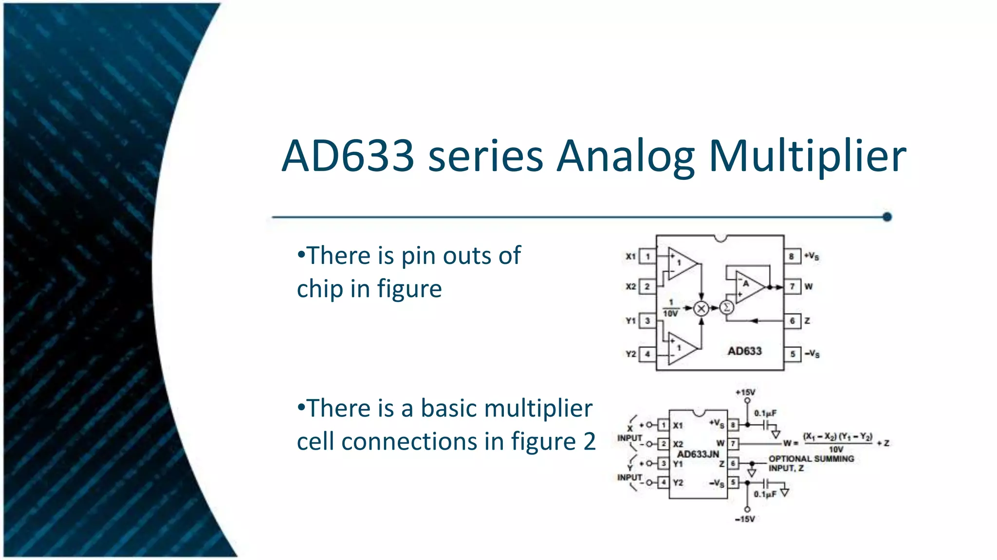
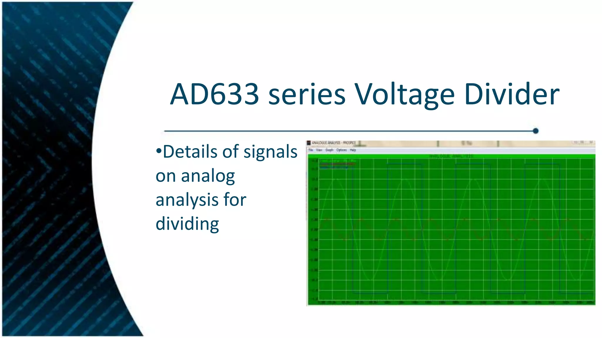
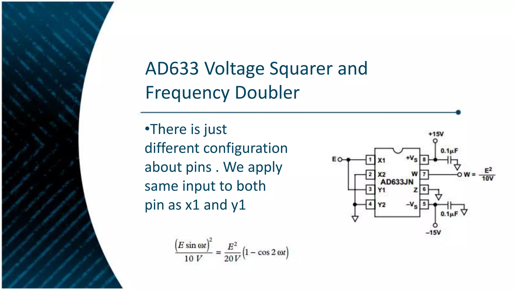
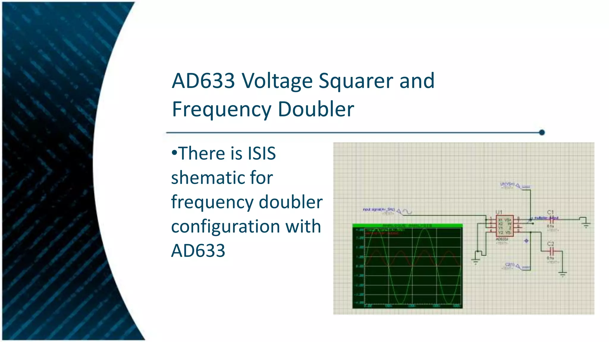
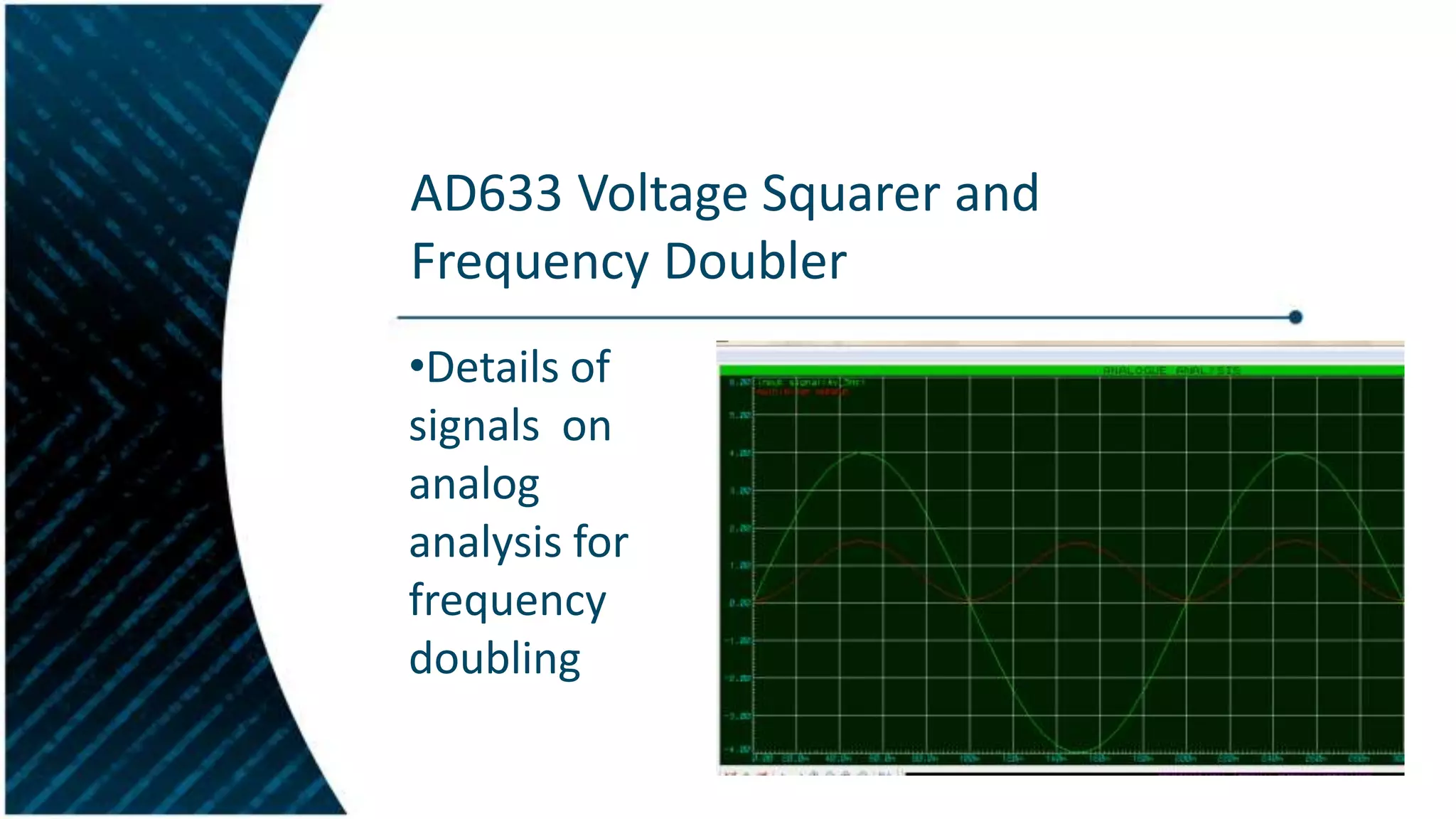
DESIGN AND IMPLEMENTATION OF
ANALOG MULTIPLIERS AND IC’s
TOLGAHAN ŞUSUR
Introduction
•Analog multipliers are used for frequency conversion and
critical components in modern radio frequency (RF)
systems.
•A mixer converts RF power at one frequency into power
at another frequency to make signal processing easier and
also inexpensive.
•A fundamental reason for frequency conversion is to
allow amplification of the received signal at a frequency
other than the RF, or the audio, frequency.
Basic Analog Multiplier
•The signal at the output is the product of
the two input signals
Multiplier and Mixer
•Mixer is a device used to mix two input signals
and deliver an output voltage at frequencies
equal to the difference or sum of the input
frequencies.
•Any nonlinear device can do the job of mixing
or modulation, but it often needs a frequency
selection network which is normally composed
as a LC network. Hence a mixer needs at least
one non-linearity, such as multiplication or
squaring, in its transfer function.
Mixer Definitions
•Mixers are non-linear devices used in systems to translate
one frequency to another. All mixer types work on the
principle that a large Local Oscillator (LO) RF drive will cause
switching/modulating the incoming Radio Frequency (RF) to
the Intermediate Frequency (IF) .The multiplication process
begins by taking two signals:
Mixer Equations
•The resulting multiplied signal will be:

•This can be multiplied out thus:
Mixer Definitions
Analog Multiplier Parameters
The following parameters are important for an analog multiplier:
•Conversion Gain: This is the ratio in dB between the IF signal which
is the difference frequency between the RF and LO signals and the RF
signal.
•Noise Figure: Noise figure is defined as the ratio of SNR(Signal to
Noise Ratio) at the IF port to the SNR of the RF port.
Mixer simulations in LabView
LabView Block Diagram for Mixer
Gilbert Cell Mixer
Two signals V1(t) and V2(t) are applied to a non linear device, which
can be characterized by a higher order polynomial function. This
polynomial function generates the terms like V1² (t), V2² (t), V1³ (t),
V2³ (t), V1² (t)*V2(t) and many others besides the desired V1(t).V2(t).
Then it is required to cancel the undesired components. This is
accomplished by a cancellation circuit configuration.
Gilbert Cell Mixer Mathematics
It is helpful to study the mathematic basis behind
the Gilbert cell. This will help us understand this
circuit better, as well as develop an appreciation
of the mixing process in general.
Let’s define the RF input voltage as
Gilbert Cell Mixer Mathematics
•Define the mixing signal:
Since this mixing signal is a
periodic waveform, we can
expand it in this Fourier series:
Gilbert Cell Mixer Mathematics
•The Gilbert cell effectively multiplies both of these
signals and in the time domain as
Giving:
where
Gilbert Cell Mixer Mathematics
• We have the sum and difference signals present
in the output (IF) voltage signal:

And all higher-ordered odd harmonics.
Multiplier with OTA
A multiplier could be realized using
programmable transconductance
components. Consider the conceptual
transconductance amplifier (OTA) , where the
output current is simply given by
Multiplier with OTA
Small signal is added to bias
current

Unwanted
componenets
Multiplier with OTA
Thus, i0(t) represents the
multiplication of two signals v1(t) and
v2(t) and an unwanted component
k2v1(t) . This component can be
eliminated as shown in figure
Applications of Multiplier IC’s
1)Voltage Multiplication
2)Voltage Divider
3)Voltage Squerer and Frequency
Doubler
AD633 series Analog Multiplier
•There is pin outs of AD633
chip in figure

•There is a basic multiplier
cell connections in figure 2
AD633 series Voltage Multiplier
•There is ISIS
shematic of AD633
for multiplier
configuration
AD633 series Voltage Multiplier
•Details of
signals on
analog
analysis for
multiplication
AD633 series Voltage Divider
•Similarly to
Multiplication there
is inverting ampifier
loop for that
transfer function:
AD633 series Voltage Divider
•There is ISIS
shematic for
divider
configuration
with AD633
AD633 series Voltage Divider
•Details of signals
on analog
analysis for
dividing
AD633 Voltage Squarer and
Frequency Doubler
•There is just
different configuration
about pins . We apply
same input to both
pin as x1 and y1
AD633 Voltage Squarer and
Frequency Doubler
•There is ISIS
shematic for
frequency doubler
configuration with
AD633
AD633 Voltage Squarer and
Frequency Doubler
•Details of
signals on
analog
analysis for
frequency
doubling
Thank You For Listening.

Design and implementation of analog multipliers with IC's

  • 1.
    DESIGN AND IMPLEMENTATIONOF ANALOG MULTIPLIERS AND IC’s TOLGAHAN ŞUSUR
  • 2.
    Introduction •Analog multipliers areused for frequency conversion and critical components in modern radio frequency (RF) systems. •A mixer converts RF power at one frequency into power at another frequency to make signal processing easier and also inexpensive. •A fundamental reason for frequency conversion is to allow amplification of the received signal at a frequency other than the RF, or the audio, frequency.
  • 3.
    Basic Analog Multiplier •Thesignal at the output is the product of the two input signals
  • 4.
    Multiplier and Mixer •Mixeris a device used to mix two input signals and deliver an output voltage at frequencies equal to the difference or sum of the input frequencies. •Any nonlinear device can do the job of mixing or modulation, but it often needs a frequency selection network which is normally composed as a LC network. Hence a mixer needs at least one non-linearity, such as multiplication or squaring, in its transfer function.
  • 5.
    Mixer Definitions •Mixers arenon-linear devices used in systems to translate one frequency to another. All mixer types work on the principle that a large Local Oscillator (LO) RF drive will cause switching/modulating the incoming Radio Frequency (RF) to the Intermediate Frequency (IF) .The multiplication process begins by taking two signals:
  • 6.
    Mixer Equations •The resultingmultiplied signal will be: •This can be multiplied out thus:
  • 7.
  • 8.
    Analog Multiplier Parameters Thefollowing parameters are important for an analog multiplier: •Conversion Gain: This is the ratio in dB between the IF signal which is the difference frequency between the RF and LO signals and the RF signal. •Noise Figure: Noise figure is defined as the ratio of SNR(Signal to Noise Ratio) at the IF port to the SNR of the RF port.
  • 9.
  • 10.
  • 11.
    Gilbert Cell Mixer Twosignals V1(t) and V2(t) are applied to a non linear device, which can be characterized by a higher order polynomial function. This polynomial function generates the terms like V1² (t), V2² (t), V1³ (t), V2³ (t), V1² (t)*V2(t) and many others besides the desired V1(t).V2(t). Then it is required to cancel the undesired components. This is accomplished by a cancellation circuit configuration.
  • 12.
    Gilbert Cell MixerMathematics It is helpful to study the mathematic basis behind the Gilbert cell. This will help us understand this circuit better, as well as develop an appreciation of the mixing process in general. Let’s define the RF input voltage as
  • 13.
    Gilbert Cell MixerMathematics •Define the mixing signal: Since this mixing signal is a periodic waveform, we can expand it in this Fourier series:
  • 14.
    Gilbert Cell MixerMathematics •The Gilbert cell effectively multiplies both of these signals and in the time domain as Giving: where
  • 15.
    Gilbert Cell MixerMathematics • We have the sum and difference signals present in the output (IF) voltage signal: And all higher-ordered odd harmonics.
  • 16.
    Multiplier with OTA Amultiplier could be realized using programmable transconductance components. Consider the conceptual transconductance amplifier (OTA) , where the output current is simply given by
  • 17.
    Multiplier with OTA Smallsignal is added to bias current Unwanted componenets
  • 18.
    Multiplier with OTA Thus,i0(t) represents the multiplication of two signals v1(t) and v2(t) and an unwanted component k2v1(t) . This component can be eliminated as shown in figure
  • 19.
    Applications of MultiplierIC’s 1)Voltage Multiplication 2)Voltage Divider 3)Voltage Squerer and Frequency Doubler
  • 20.
    AD633 series AnalogMultiplier •There is pin outs of AD633 chip in figure •There is a basic multiplier cell connections in figure 2
  • 21.
    AD633 series VoltageMultiplier •There is ISIS shematic of AD633 for multiplier configuration
  • 22.
    AD633 series VoltageMultiplier •Details of signals on analog analysis for multiplication
  • 23.
    AD633 series VoltageDivider •Similarly to Multiplication there is inverting ampifier loop for that transfer function:
  • 24.
    AD633 series VoltageDivider •There is ISIS shematic for divider configuration with AD633
  • 25.
    AD633 series VoltageDivider •Details of signals on analog analysis for dividing
  • 26.
    AD633 Voltage Squarerand Frequency Doubler •There is just different configuration about pins . We apply same input to both pin as x1 and y1
  • 27.
    AD633 Voltage Squarerand Frequency Doubler •There is ISIS shematic for frequency doubler configuration with AD633
  • 28.
    AD633 Voltage Squarerand Frequency Doubler •Details of signals on analog analysis for frequency doubling
  • 29.
    Thank You ForListening.