Download to read offline
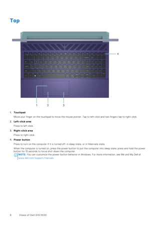
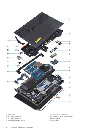
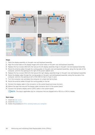


![System and setup password
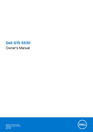
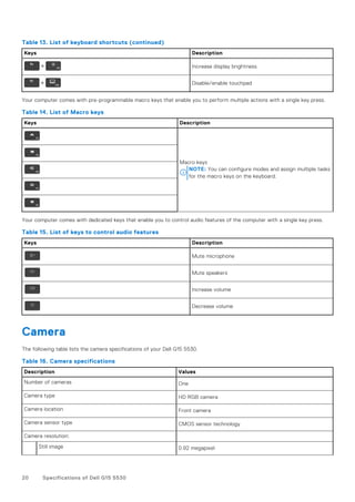
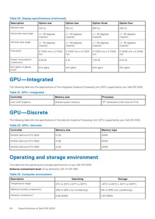
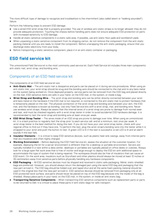
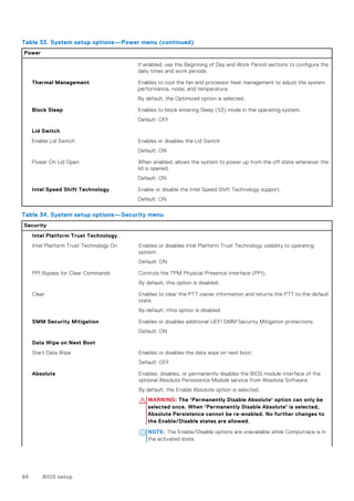
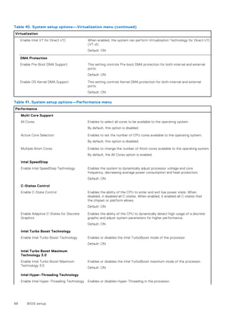
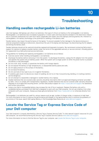
Table 43. System and setup password
Password type Description
System password Password that you must enter to log in to your system.
Setup password Password that you must enter to access and make changes to
the BIOS settings of your computer.
You can create a system password and a setup password to secure your computer.
CAUTION: The password features provide a basic level of security for the data on your computer.
CAUTION: Anyone can access the data that is stored on your computer if it is not locked and left unattended.
NOTE: System and setup password feature is disabled.
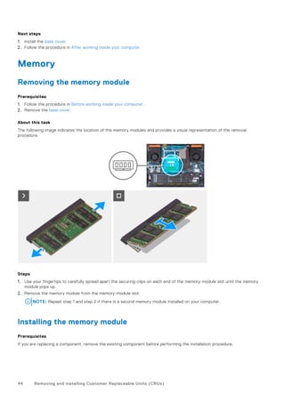
Assigning a system setup password
Prerequisites
You can assign a new System or Admin Password only when the status is in Not Set.
About this task
To enter the system setup, press F12 immediately after a power-on or reboot.
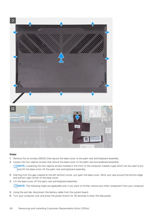
Steps
1. In the System BIOS or System Setup screen, select Security and press Enter.
The Security screen is displayed.
2. Select System/Admin Password and create a password in the Enter the new password field.
Use the following guidelines to assign the system password:
● A password can have up to 32 characters.
● At least one special character: ! " # $ % & ' ( ) * + , - . / : ; < = > ? @ [ ] ^ _ ` { | }
● Numbers 0 through 9.
● Upper case letters from A to Z.
● Lower case letters from a to z.
3. Type the system password that you entered earlier in the Confirm new password field and click OK.
4. Press Esc and save the changes as prompted by the pop-up message.
5. Press Y to save the changes.
The computer restarts.
Deleting or changing an existing system setup password
Prerequisites
Ensure that the Password Status is Unlocked (in the System Setup) before attempting to delete or change the existing
System and/or Setup password. You cannot delete or change an existing System or Setup password, if the Password Status is
Locked.
About this task
To enter the System Setup, press F12 immediately after a power-on or reboot.
BIOS setup 101](https://image.slidesharecdn.com/dell-g15-5530-owners-manual-en-us-231107042430-ca9c1ed8/85/Dell-Gaming-G15-5530-2023-101-320.jpg)
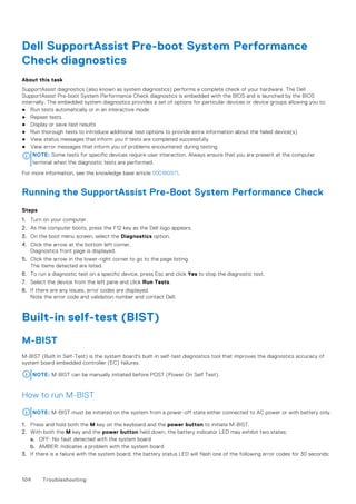
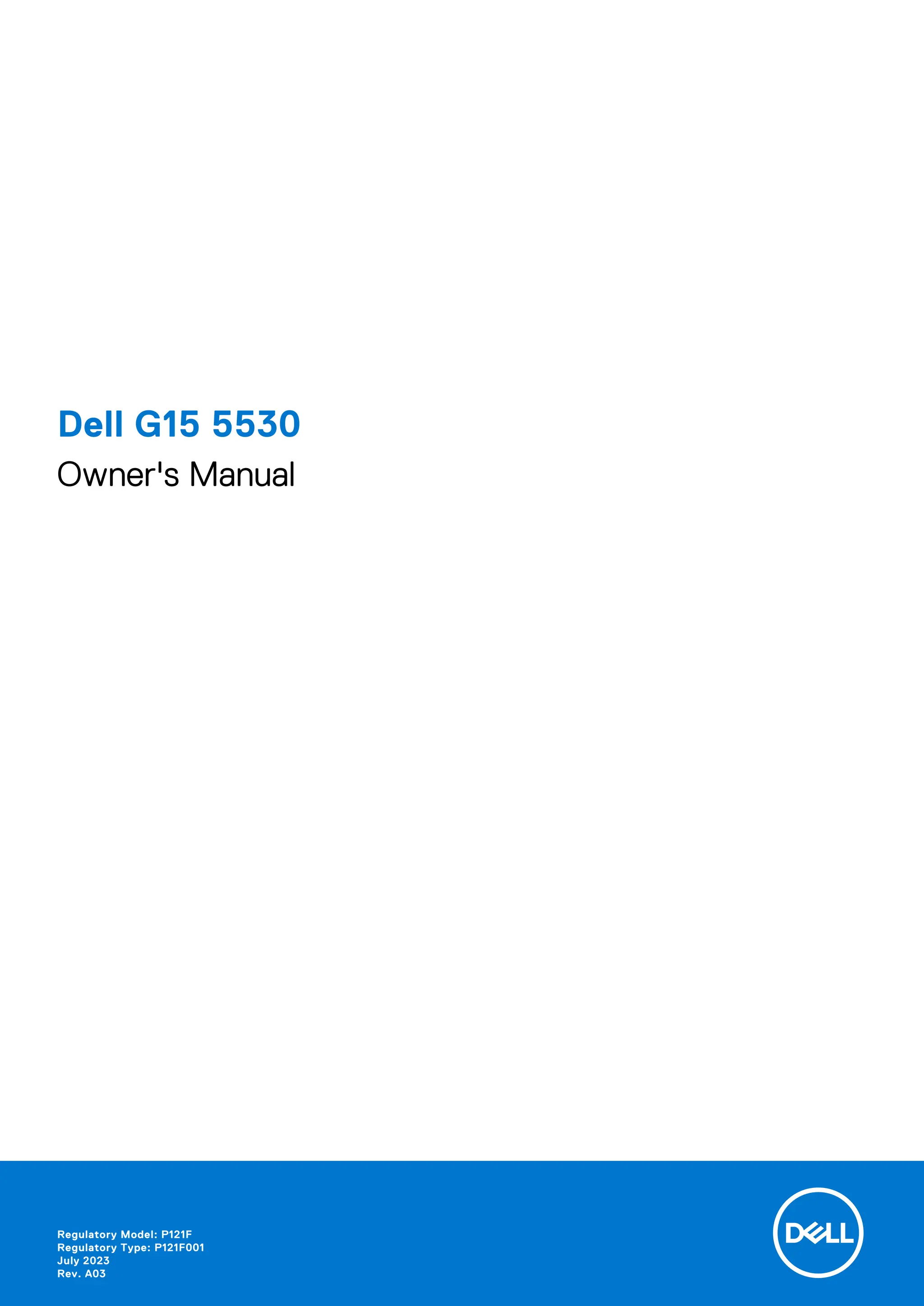
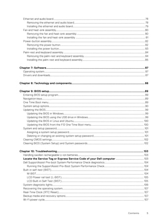
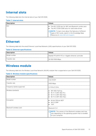
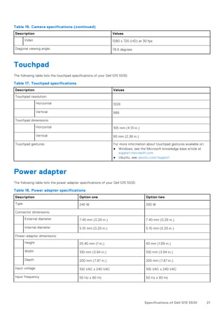
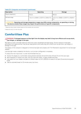
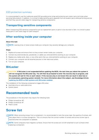
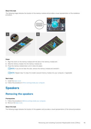
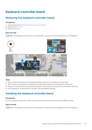
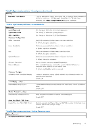
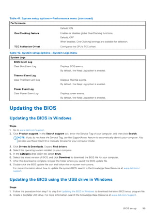
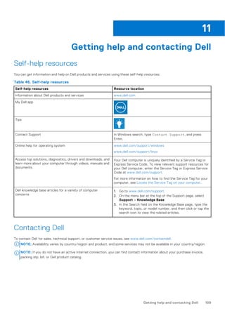
![Table 44. LED error codes
Blinking Pattern Possible Problem
Amber White
2 1 CPU Failure
2 8 LCD Power Rail Failure
1 1 TPM Detection Failure
2 4 Memory/RAM failure
4. If there is no failure with the system board, the LCD will cycle through the solid color screens described in the LCD-BIST
section for 30 seconds and then power off.
LCD Power rail test (L-BIST)
L-BIST is an enhancement to the single LED error code diagnostics and is automatically initiated during POST. L-BIST will check
the LCD power rail. If there is no power being supplied to the LCD (that is if the L-BIST circuit fails), the battery status LED will
flash either an error code [2,8] or an error code [2,7].
NOTE: If L-BIST fails, LCD-BIST cannot function as no power will be supplied to the LCD.
How to invoke L-BIST Test:
1. Press the power button to start the system.
2. If the system does not start up normally, look at the battery status LED:
● If the battery status LED flashes an error code [2,7], the display cable may not be connected properly.
● If the battery status LED flashes an error code [2,8], there is a failure on the LCD power rail of the system board, hence
there is no power supplied to the LCD.
3. For cases, when a [2,7] error code is shown, check to see if the display cable is properly connected.
4. For cases when a [2,8] error code is shown, replace the system board.
LCD Built-in Self Test (BIST)
Dell laptops have a built-in diagnostic tool that helps you determine if the screen abnormality you are experiencing is an inherent
problem with the LCD (screen) of the Dell laptop or with the video card (GPU) and PC settings.
When you notice screen abnormalities like flickering, distortion, clarity issues, fuzzy or blurry image, horizontal or vertical lines,
color fade etc., it is always a good practice to isolate the LCD (screen) by running the Built-In Self Test (BIST).
How to invoke LCD BIST Test
1. Power off the Dell laptop.
2. Disconnect any peripherals that are connected to the laptop. Connect only the AC adapter (charger) to the laptop.
3. Ensure that the LCD (screen) is clean (no dust particles on the surface of the screen).
4. Press and hold D key and Power on the laptop to enter LCD built-in self test (BIST) mode. Continue to hold the D key, until
the system boots up.
5. The screen will display solid colors and change colors on the entire screen to white, black, red, green, and blue twice.
6. Then it will display the colors white, black and red.
7. Carefully inspect the screen for abnormalities (any lines, fuzzy color or distortion on the screen).
8. At the end of the last solid color (red), the system will shut down.
NOTE: Dell SupportAssist Pre-boot diagnostics upon launch, initiates an LCD BIST first, expecting a user intervention
confirm functionality of the LCD.
Troubleshooting 105](https://image.slidesharecdn.com/dell-g15-5530-owners-manual-en-us-231107042430-ca9c1ed8/85/Dell-Gaming-G15-5530-2023-105-320.jpg)

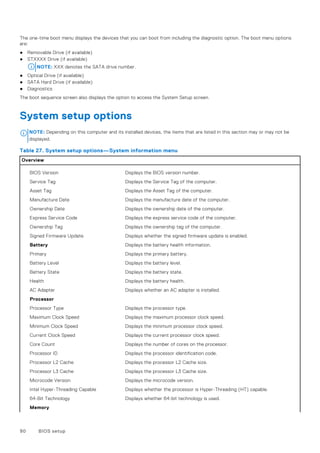
The Dell G15 5530 owner's manual outlines essential information about the laptop, including its specifications, setup instructions, and troubleshooting tips. Key sections encompass views of the laptop, internal components, software management, and safety guidelines for handling hardware. The manual emphasizes the importance of precautions to avoid potential damage and provides guidance on using Dell applications for improved user experience.


