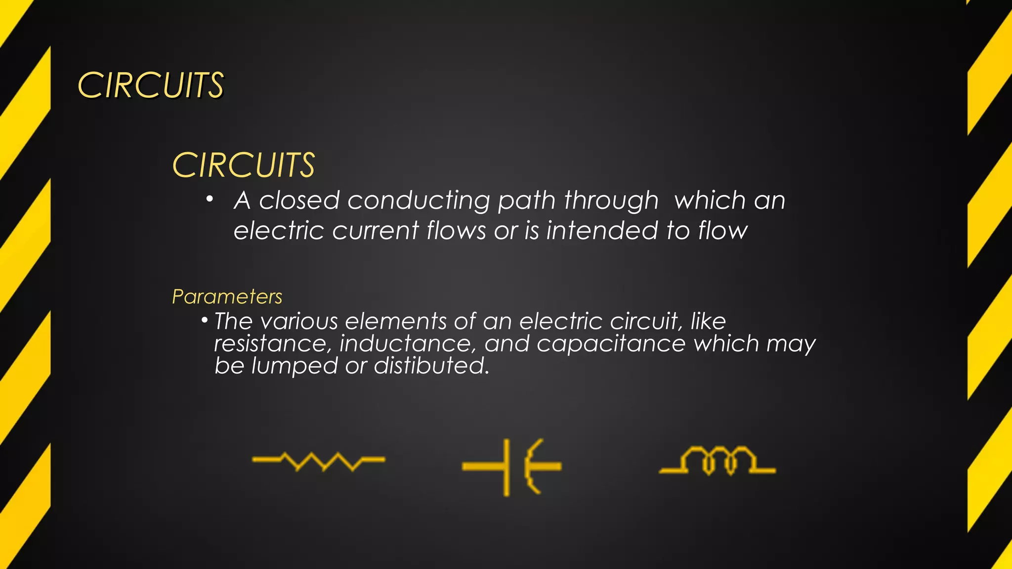
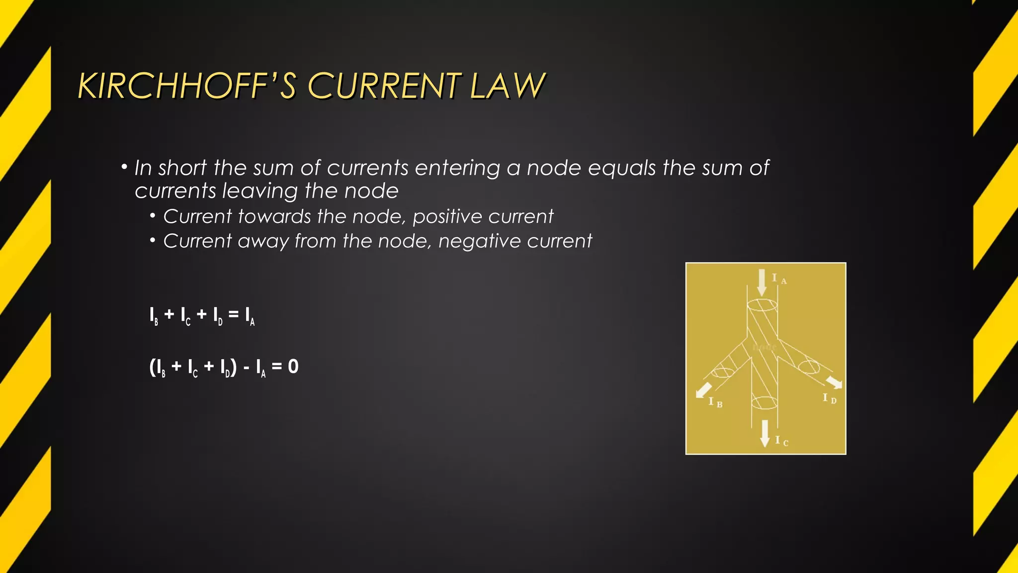
DC CircuitsDC CircuitsDC CircuitsDC Circuits
CIRCUITSCIRCUITS
Parameters
• The various elements of an electric circuit, like
resistance, inductance, and capacitance which may
be lumped or distibuted.
CIRCUITS
• A closed conducting path through which an
electric current flows or is intended to flow
CIRCUITSCIRCUITS
Linear Circuit
Is one whose parameters are constant (i.e. They do not
change with voltage and current.
Non-Linear Circuit
Is that circuit whose parameters change with voltage and
current.
Bilateral Circuit
Is one whose properties or characteristics are the same in
either direction.
Unilateral Circuit
Is that circuit whose properties or characteristics change
with the direction of its operation.
TYPES
ELECTRICAL NETWORKSELECTRICAL NETWORKS
Passive Network
• With no source of emf.
Active Network
• Contains one or more than one sources of emf.
ELECTRICAL NETWORK
• Connection of various electric elements in any manner
TYPES
ELECTRICAL NETWORKSELECTRICAL NETWORKS
Node
• A junction in a circuit where two or more circuit elements and/or branches are
connected together.
Branch
• Part of a network which lies netween two junctions.
Loop
• A closed path in a circuit in which no element or node is encountered more
than once.
Mesh
• A loop that contains no other loop within it.
PARTS
OHM’S LAWOHM’S LAW
OHM’S LAW
• One of the most fundamental law in electrical circuits
relating voltage, current and resistance
• Developed in 1827 by German physicist Georg Simon Ohm
OHM’S LAWOHM’S LAW
• According to Ohm’s Law, the current (I) flowing in an electrical
circuit is directly is directly proportional to the applied voltage (E)
and inversely proportional to the equivalent resistance (R) of the
circuit and mathematically expressed as:
SERIES CIRCUITSSERIES CIRCUITS
SERIES circuits
• A circuit connection in which the components are
connected to form one conducting path
SERIES CIRCUITSSERIES CIRCUITS
Where: EX – voltage across the resistor concerned
ET – total voltage across the circuit
RX – the resistor concerned
RT – the sum of all resistances in the circuit
Voltage Division for Series Circuit:
EX = ET • RX
RT
PARALLEL CIRCUITSPARALLEL CIRCUITS
PARALLEL circuits
• A circuit connection in which the components are
connected to form more than 1 conducting path
PARALLEL CIRCUITSPARALLEL CIRCUITS
Where: IX – current concerned flowing through resistor Rx
IT – total current of the circuit
Req – equivalent resistance of the parallel circuit except Rx
RT – the sum of all resistances in the circuit
Voltage Division for Parallel Circuit:
IX = IT • Req
RT
KIRCHHOFF’S LAWKIRCHHOFF’S LAW
“In any electrical network, the algebraic sum of the current meeting
at a point (or junction) is zero.”
KIRCHHOFF’S LAW
• More comprehensive than Ohm’s Law and is used in solving
electrical
• Termed as “Laws of Electric Networks”
• Formulated by German physicist Gustav Robert Kirchhoff
Kirchhoff’s Current Law (KCL)
KIRCHHOFF’S CURRENT LAWKIRCHHOFF’S CURRENT LAW
• In short the sum of currents entering a node equals the sum of
currents leaving the node
• Current towards the node, positive current
• Current away from the node, negative current
IB + IC + ID = IA
(IB + IC + ID) - IA = 0
KIRCHHOFF’S VOLTAGE LAWKIRCHHOFF’S VOLTAGE LAW
“The algebraic sum of the products of currents and
resistances in each of thr conductors in any closed path (or
mesh) in a network PLUS the algebraic sum of the emfs in
the path is zero.”
Kirchhoff’s Voltage Law (KVL)
KIRCHHOFF’S VOLTAGE LAWKIRCHHOFF’S VOLTAGE LAW
• In short, the sum of the voltages around the loop is equal to
zero
• For voltage sources, if loops enters on minus and goes out on plus,
positive voltage and if loops enters on plus and goes out on minus,
negative voltage.
• For voltage drops, if the loop direction is the same as current
direction, negative voltage drop and if the loop direction is
opposite to the current direction, positive voltage drop.
MESH ANALYSISMESH ANALYSIS
Loop Analysis Procedure:
1.Label each of the loop/mesh currents.
2.Apply KVL to loops/meshes to form
equations with current variables.
a. For N independent loops, we may
write N total equations using KVL
around each loop. Loop currents are
those currents flowing in a loop; they
are used to define branch currents.
b. Current sources provide constraint
equations.
3.Solve the equations to determine the
user defined loop currents.
MESH analysis
• A sophisticated application of KVL with mesh
currents.
NODAL ANALYSISNODAL ANALYSIS
• Consist of finding the node
voltages at all principal nodes with
respect to the reference node.
• PRINCIPAL node – a node with
three or more circuit elements
joined together.
• Reference node – the node from
which the unknown voltages are
measured.
NODAL analysis
• A systematic application of KCL at a node and after
simplifying the resulting KCL equation, the node voltage can
be calculated.
SUPERPOSITION THEOREMSUPERPOSITION THEOREM
In general:
• Number of network to analyze is equal to number of
independent sources.
• To consider effects of each source independently, sources
must be removed and replaced without affecting the final
result:
• All voltage sources >> short circuited
• All current sources >> open circuited
SUPERPOSITION theorem
“ The current through or voltage across, an element in a linear
bilateral network is equal to the algebraic sum of the current or
voltages produced independently in each source. ”
COMPENSATION THEOREMCOMPENSATION THEOREM
COMPENSATION theorem
• If the impedance Z of a branch in a network in which a
current I flows is changed by a finite amount dZ, then the
change in the currents in all other branches of the network
may be calculated by inserting a voltage source of -IdZ into
that branch with all other voltage sources replaced by their
internal impedances.
RECIPROCITY THEOREMRECIPROCITY THEOREM
Simply mean,
 E and I are mutually transferable, or
 The receiving point and the sending point in a network are
interchangeable, or
 Interchange of an IDEAL voltage source and an IDEAL ammeter in
any network will not change the ammeter reading,
 Interchange of an IDEAL current source and an IDEAL voltmeter in
any network will not change the voltmeter reading
RECIPROCITY theorem
“If a voltage source E acting in one branch of a network causes a
current I to flow in another branch of the network, then the same
voltage source E acting in the second branch would cause an identical
current I to flow in the first branch. ”
MILLMAN’S THEOREMMILLMAN’S THEOREM
• In Millman’s Theorem, the circuit is re-drawn as a parallel
network of branches, each branch containing a resistor or
series battery/resistor combination.
• Millman’s theorem is applicable only to those cicuits which can
be re-drawn accordingly.
MILLMAN’S theorem
“ A special case of the application of Thevenin’s Theorem/or
Norton’s Theorem used for finding the COMMON voltage (VAB)
across any network which contains a number of parallel voltage
sources. ”
MAXIMUM POWER TRANSFER THOREMMAXIMUM POWER TRANSFER THOREM
MAXIMUM POWER TRANSFER theorem
• For loads connected directly to a DC voltage supply,
maximum power will be delivered to the load when the
resistance is equal to the internal resistance of the source.
• For maximum power transfer: RS = RL
THEVENIN’S THEOREMTHEVENIN’S THEOREM
where:
VTH – the open circuit voltage which appears across the two terminals from where
the load resistance has been removed.
RTH – the resistance looking back into the network across the two terminals with all
the voltage sources shorted and replaced by their internal resistances (if any)
and all current sources by infinite resistance.
THEVENIN’S theorem
“ Any two-terminal of a linear, active bilateral
network of a fixed resistances and voltage source/s
may be replaced by a single voltage source (VTH) and
a series of internal resistance (RTH). ”
NORTON’S THEOREMNORTON’S THEOREM
where:
IN– the current which would flow in a short circuit placed across the output terminals.
RN – the resistance of the network when viewed from the open circuited terminals after
all voltage sources being replaced by open circuits.
THEVENIN’S theorem
“ Any two-terminal active network containing voltage
sources and resistances when viewed from its output
terminals, is equivalent to a constant-current source (IN)
and a parallel internal resistance (RN). ”
THEVENIN-NORTON TRANSFORMATIONTHEVENIN-NORTON TRANSFORMATION
NORTON-THEVENIN TRANSFORMATIONNORTON-THEVENIN TRANSFORMATION
EQUIVALENT THREE-TERMINAL NETWORKSEQUIVALENT THREE-TERMINAL NETWORKS
DELTA to WYE
• The equivalent resistance of each arm to the wye is given
by the PRODUCT of the two delta sides that meet at its end
divided by the SUM of the three delta resistances.
EQUIVALENT THREE-TERMINAL NETWORKSEQUIVALENT THREE-TERMINAL NETWORKS
WYE to DELTA
• The equivalent delta resistance between any two twrminals is given
by the SUM of a star resistance between those terminals PLUS the
PRODUCT of these two star resistances DIVIDED by the third resistance.
Skillcruise.com

dc circuits

  • 1.
    DC CircuitsDC CircuitsDCCircuitsDC Circuits
  • 2.
    CIRCUITSCIRCUITS Parameters • The variouselements of an electric circuit, like resistance, inductance, and capacitance which may be lumped or distibuted. CIRCUITS • A closed conducting path through which an electric current flows or is intended to flow
  • 3.
    CIRCUITSCIRCUITS Linear Circuit Is onewhose parameters are constant (i.e. They do not change with voltage and current. Non-Linear Circuit Is that circuit whose parameters change with voltage and current. Bilateral Circuit Is one whose properties or characteristics are the same in either direction. Unilateral Circuit Is that circuit whose properties or characteristics change with the direction of its operation. TYPES
  • 4.
    ELECTRICAL NETWORKSELECTRICAL NETWORKS PassiveNetwork • With no source of emf. Active Network • Contains one or more than one sources of emf. ELECTRICAL NETWORK • Connection of various electric elements in any manner TYPES
  • 5.
    ELECTRICAL NETWORKSELECTRICAL NETWORKS Node •A junction in a circuit where two or more circuit elements and/or branches are connected together. Branch • Part of a network which lies netween two junctions. Loop • A closed path in a circuit in which no element or node is encountered more than once. Mesh • A loop that contains no other loop within it. PARTS
  • 6.
    OHM’S LAWOHM’S LAW OHM’SLAW • One of the most fundamental law in electrical circuits relating voltage, current and resistance • Developed in 1827 by German physicist Georg Simon Ohm
  • 7.
    OHM’S LAWOHM’S LAW •According to Ohm’s Law, the current (I) flowing in an electrical circuit is directly is directly proportional to the applied voltage (E) and inversely proportional to the equivalent resistance (R) of the circuit and mathematically expressed as:
  • 8.
    SERIES CIRCUITSSERIES CIRCUITS SERIEScircuits • A circuit connection in which the components are connected to form one conducting path
  • 9.
    SERIES CIRCUITSSERIES CIRCUITS Where:EX – voltage across the resistor concerned ET – total voltage across the circuit RX – the resistor concerned RT – the sum of all resistances in the circuit Voltage Division for Series Circuit: EX = ET • RX RT
  • 10.
    PARALLEL CIRCUITSPARALLEL CIRCUITS PARALLELcircuits • A circuit connection in which the components are connected to form more than 1 conducting path
  • 11.
    PARALLEL CIRCUITSPARALLEL CIRCUITS Where:IX – current concerned flowing through resistor Rx IT – total current of the circuit Req – equivalent resistance of the parallel circuit except Rx RT – the sum of all resistances in the circuit Voltage Division for Parallel Circuit: IX = IT • Req RT
  • 12.
    KIRCHHOFF’S LAWKIRCHHOFF’S LAW “Inany electrical network, the algebraic sum of the current meeting at a point (or junction) is zero.” KIRCHHOFF’S LAW • More comprehensive than Ohm’s Law and is used in solving electrical • Termed as “Laws of Electric Networks” • Formulated by German physicist Gustav Robert Kirchhoff Kirchhoff’s Current Law (KCL)
  • 13.
    KIRCHHOFF’S CURRENT LAWKIRCHHOFF’SCURRENT LAW • In short the sum of currents entering a node equals the sum of currents leaving the node • Current towards the node, positive current • Current away from the node, negative current IB + IC + ID = IA (IB + IC + ID) - IA = 0
  • 14.
    KIRCHHOFF’S VOLTAGE LAWKIRCHHOFF’SVOLTAGE LAW “The algebraic sum of the products of currents and resistances in each of thr conductors in any closed path (or mesh) in a network PLUS the algebraic sum of the emfs in the path is zero.” Kirchhoff’s Voltage Law (KVL)
  • 15.
    KIRCHHOFF’S VOLTAGE LAWKIRCHHOFF’SVOLTAGE LAW • In short, the sum of the voltages around the loop is equal to zero • For voltage sources, if loops enters on minus and goes out on plus, positive voltage and if loops enters on plus and goes out on minus, negative voltage. • For voltage drops, if the loop direction is the same as current direction, negative voltage drop and if the loop direction is opposite to the current direction, positive voltage drop.
  • 16.
    MESH ANALYSISMESH ANALYSIS LoopAnalysis Procedure: 1.Label each of the loop/mesh currents. 2.Apply KVL to loops/meshes to form equations with current variables. a. For N independent loops, we may write N total equations using KVL around each loop. Loop currents are those currents flowing in a loop; they are used to define branch currents. b. Current sources provide constraint equations. 3.Solve the equations to determine the user defined loop currents. MESH analysis • A sophisticated application of KVL with mesh currents.
  • 17.
    NODAL ANALYSISNODAL ANALYSIS •Consist of finding the node voltages at all principal nodes with respect to the reference node. • PRINCIPAL node – a node with three or more circuit elements joined together. • Reference node – the node from which the unknown voltages are measured. NODAL analysis • A systematic application of KCL at a node and after simplifying the resulting KCL equation, the node voltage can be calculated.
  • 18.
    SUPERPOSITION THEOREMSUPERPOSITION THEOREM Ingeneral: • Number of network to analyze is equal to number of independent sources. • To consider effects of each source independently, sources must be removed and replaced without affecting the final result: • All voltage sources >> short circuited • All current sources >> open circuited SUPERPOSITION theorem “ The current through or voltage across, an element in a linear bilateral network is equal to the algebraic sum of the current or voltages produced independently in each source. ”
  • 19.
    COMPENSATION THEOREMCOMPENSATION THEOREM COMPENSATIONtheorem • If the impedance Z of a branch in a network in which a current I flows is changed by a finite amount dZ, then the change in the currents in all other branches of the network may be calculated by inserting a voltage source of -IdZ into that branch with all other voltage sources replaced by their internal impedances.
  • 20.
    RECIPROCITY THEOREMRECIPROCITY THEOREM Simplymean,  E and I are mutually transferable, or  The receiving point and the sending point in a network are interchangeable, or  Interchange of an IDEAL voltage source and an IDEAL ammeter in any network will not change the ammeter reading,  Interchange of an IDEAL current source and an IDEAL voltmeter in any network will not change the voltmeter reading RECIPROCITY theorem “If a voltage source E acting in one branch of a network causes a current I to flow in another branch of the network, then the same voltage source E acting in the second branch would cause an identical current I to flow in the first branch. ”
  • 21.
    MILLMAN’S THEOREMMILLMAN’S THEOREM •In Millman’s Theorem, the circuit is re-drawn as a parallel network of branches, each branch containing a resistor or series battery/resistor combination. • Millman’s theorem is applicable only to those cicuits which can be re-drawn accordingly. MILLMAN’S theorem “ A special case of the application of Thevenin’s Theorem/or Norton’s Theorem used for finding the COMMON voltage (VAB) across any network which contains a number of parallel voltage sources. ”
  • 22.
    MAXIMUM POWER TRANSFERTHOREMMAXIMUM POWER TRANSFER THOREM MAXIMUM POWER TRANSFER theorem • For loads connected directly to a DC voltage supply, maximum power will be delivered to the load when the resistance is equal to the internal resistance of the source. • For maximum power transfer: RS = RL
  • 23.
    THEVENIN’S THEOREMTHEVENIN’S THEOREM where: VTH– the open circuit voltage which appears across the two terminals from where the load resistance has been removed. RTH – the resistance looking back into the network across the two terminals with all the voltage sources shorted and replaced by their internal resistances (if any) and all current sources by infinite resistance. THEVENIN’S theorem “ Any two-terminal of a linear, active bilateral network of a fixed resistances and voltage source/s may be replaced by a single voltage source (VTH) and a series of internal resistance (RTH). ”
  • 24.
    NORTON’S THEOREMNORTON’S THEOREM where: IN–the current which would flow in a short circuit placed across the output terminals. RN – the resistance of the network when viewed from the open circuited terminals after all voltage sources being replaced by open circuits. THEVENIN’S theorem “ Any two-terminal active network containing voltage sources and resistances when viewed from its output terminals, is equivalent to a constant-current source (IN) and a parallel internal resistance (RN). ”
  • 25.
  • 26.
  • 27.
    EQUIVALENT THREE-TERMINAL NETWORKSEQUIVALENTTHREE-TERMINAL NETWORKS DELTA to WYE • The equivalent resistance of each arm to the wye is given by the PRODUCT of the two delta sides that meet at its end divided by the SUM of the three delta resistances.
  • 28.
    EQUIVALENT THREE-TERMINAL NETWORKSEQUIVALENTTHREE-TERMINAL NETWORKS WYE to DELTA • The equivalent delta resistance between any two twrminals is given by the SUM of a star resistance between those terminals PLUS the PRODUCT of these two star resistances DIVIDED by the third resistance.
  • 29.