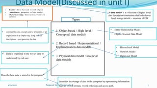
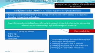
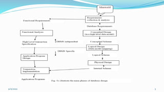
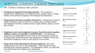
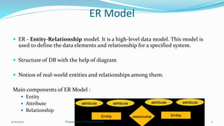
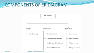
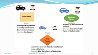
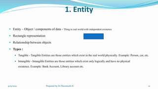
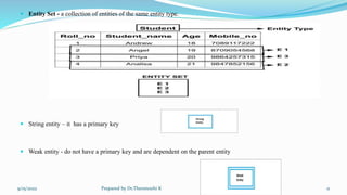
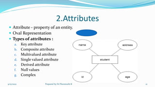
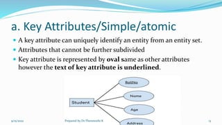
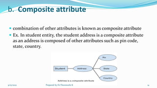
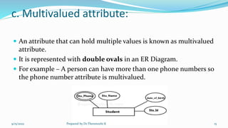
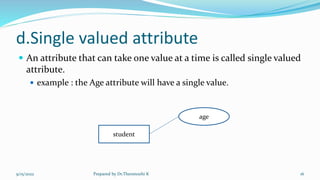
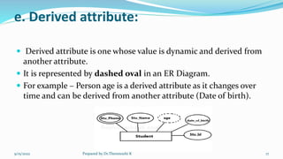
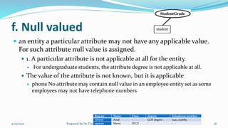
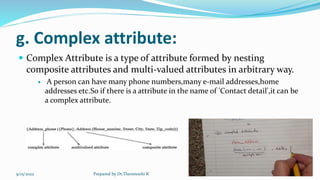
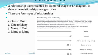
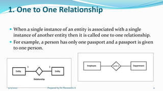
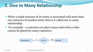
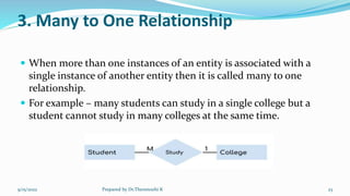
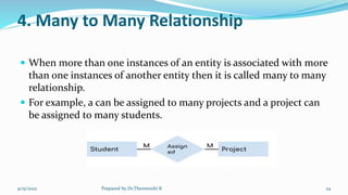
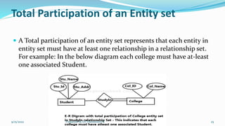
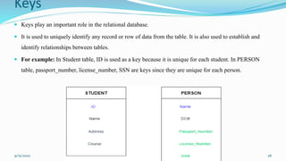
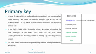
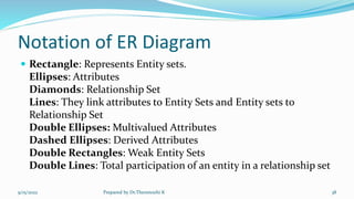
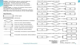
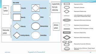
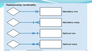
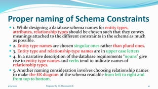
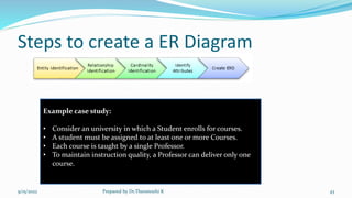
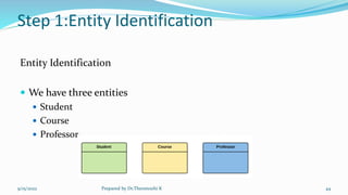
Data Model
Data Modeling Using The ER Model: High Level Conceptual Data Models For DB Design With An Example;
Entity Types; Entity Sets; Attributes Keys; Keys; ER Model Concepts; Notation For ER Diagrams; Proper
Naming Of Schema Constructs; Relationship Types Of Degree Higher Than Two.
Data Model
 Data – Collection of information
 Database – Collection of data
 Data Model - To show how data is stored, connected, accessed and
updated in the database management system.
9/15/2022 Prepared by Dr.Thenmozhi K 2
 1. Object based / High-level /
Conceptual data models
 2. Record based / Representational /
Implementation data models
 3. Physical data model / low-level
data models
Data Model(Discussed in unit I)
Types
A data model is a collection of higher level
data description constraints that hides lower
level storage details – structure of DB
• Entity-Relationship Model
• Object-Oriented Data Model
• Hierarchical Model
• Network Model
• Relational Model
• conveys the core concepts and/or principles of an
organization in a simple way, using concise
descriptions – user perceive the data
Describe how data is stored in the computer
• Data is organized in the way of easy to
understand by end user
describes the storage of data in the computer by representing information
such as record formats, record orderings and access path.
9/15/2022 Prepared by Dr.Thenmozhi K 3
High Level Conceptual Data Model for Database Design
a map of concepts and their relationships used
for databases
Entity relationship(ER) Model is a popular high level conceptual data model.
• functional requirements consist of user defined operations that will be applied to the database
including both retrieval and updates.
Once all the requirements have been collected and analyzed, the next step is to create a conceptual
schema for the database using a high level conceptual data model
Conceptual design
Conceptual schema
• Entity type
• Relationships
• constrains overall database design involves the following steps:
1) Identifying all the required files.
2) Identifying the fields of each of these files.
3) Identifying the primary key of each of these files.
4) Identifying the relationships between files.
9/15/2022 Prepared by Dr.Thenmozhi K 4
9/15/2022 5
A Sample COMPANY Database Application
 DB – Company ( employees, depts., projects)
 Company is organized into departments - The company is
organized into departments each department has a unique name, a unique
number and a particular employee who manages the department.
 Department controls a number of projects -A department controls a
number of project, each of which has a unique name, a unique number
each employee will have employee name, empid, address, salary, sex and
date of birth.
 Employee: store each employee’s name, Social Security number,
address, salary, sex (gender), and birth date - An employee is
assigned to one department but may work on several projects, which are
not necessarily controlled by the same department. Number of hours per
week that an employee works on each project is to be noted.
 Keep track of the dependents of each employee -Also each
employee may have one or more dependents. These details are to be
maintained for insurance purposes. The dependent’s name, sex, birth date
and relationship to the employee are maintained.
9/15/2022 Prepared by Dr.Thenmozhi K 6
ER Model
 ER - Entity-Relationship model. It is a high-level data model. This model is
used to define the data elements and relationship for a specified system.
 Structure of DB with the help of diagram
 Notion of real-world entities and relationships among them.
Main components of ER Model :
 Entity
 Attribute
 Relationship
9/15/2022 Prepared by Dr.Thenmozhi K 7
COMPONENTS OF ER DIAGRAM
9/15/2022 Prepared by Dr.Thenmozhi K 8
9/15/2022 Prepared by Dr.Thenmozhi K 9
1. Entity
 Entity – Object / components of data - Thing in real world with independent existence
 Rectangle representation
 Relationship between objects
 Types :
 Tangible - Tangible Entities are those entities which exist in the real world physically. Example: Person, car, etc.
 Intangible - Intangible Entities are those entities which exist only logically and have no physical
existence. Example: Bank Account, Library account etc.
9/15/2022 Prepared by Dr.Thenmozhi K 10
 Entity Set - a collection of entities of the same entity type.
 String entity – it has a primary key
 Weak entity - do not have a primary key and are dependent on the parent entity
9/15/2022 Prepared by Dr.Thenmozhi K 11
2.Attributes
 Attribute - property of an entity.
 Oval Representation
 Types of attributes :
a. Key attribute
b. Composite attribute
c. Multivalued attribute
d. Single valued attribute
e. Derived attribute
f. Null values
g. Complex
9/15/2022 Prepared by Dr.Thenmozhi K 12
a. Key Attributes/Simple/atomic
 A key attribute can uniquely identify an entity from an entity set.
 Attributes that cannot be further subdivided
 Key attribute is represented by oval same as other attributes
however the text of key attribute is underlined.
9/15/2022 Prepared by Dr.Thenmozhi K 13
b. Composite attribute
 combination of other attributes is known as composite attribute
 Ex. In student entity, the student address is a composite attribute
as an address is composed of other attributes such as pin code,
state, country.
9/15/2022 Prepared by Dr.Thenmozhi K 14
c. Multivalued attribute:
 An attribute that can hold multiple values is known as multivalued
attribute.
 It is represented with double ovals in an ER Diagram.
 For example – A person can have more than one phone numbers so
the phone number attribute is multivalued.
9/15/2022 Prepared by Dr.Thenmozhi K 15
d.Single valued attribute
 An attribute that can take one value at a time is called single valued
attribute.
 example : the Age attribute will have a single value.
9/15/2022 Prepared by Dr.Thenmozhi K 16
student
age
e. Derived attribute:
 Derived attribute is one whose value is dynamic and derived from
another attribute.
 It is represented by dashed oval in an ER Diagram.
 For example – Person age is a derived attribute as it changes over
time and can be derived from another attribute (Date of birth).
9/15/2022 Prepared by Dr.Thenmozhi K 17
f. Null valued
 an entity a particular attribute may not have any applicable value.
For such attribute null value is assigned.
 1. A particular attribute is not applicable at all for the entity.
 For undergraduate students, the attribute degree is not applicable at all.
 The value of the attribute is not known, but it is applicable
 phone No attribute may contain null value in an employee entity set as some
employees may not have telephone numbers
9/15/2022 Prepared by Dr.Thenmozhi K 18
Reg.no Name Class degree Telephone number
17cs101 Ansil - GOT degree 0423 225689
19cs101 Marry III CS - -
g. Complex attribute:
 Complex Attribute is a type of attribute formed by nesting
composite attributes and multi-valued attributes in arbitrary way.
 A person can have many phone numbers,many e-mail addresses,home
addresses etc.So if there is a attribute in the name of 'Contact detail',it can be
a complex attribute.
9/15/2022 Prepared by Dr.Thenmozhi K 19
3. Relationship
 A relationship is represented by diamond shape in ER diagram, it
shows the relationship among entities.
 There are four types of relationships:

1. One to One
2. One to Many
3. Many to One
4. Many to Many
9/15/2022 Prepared by Dr.Thenmozhi K 20
1. One to One Relationship
 When a single instance of an entity is associated with a single
instance of another entity then it is called one to one relationship.
 For example, a person has only one passport and a passport is given
to one person.
9/15/2022 Prepared by Dr.Thenmozhi K 21
2. One to Many Relationship
 When a single instance of an entity is associated with more than
one instances of another entity then it is called one to many
relationship.
 For example – a customer can place many orders but a order
cannot be placed by many customers.
9/15/2022 Prepared by Dr.Thenmozhi K 22
3. Many to One Relationship
 When more than one instances of an entity is associated with a
single instance of another entity then it is called many to one
relationship.
 For example – many students can study in a single college but a
student cannot study in many colleges at the same time.
9/15/2022 Prepared by Dr.Thenmozhi K 23
4. Many to Many Relationship
 When more than one instances of an entity is associated with more
than one instances of another entity then it is called many to many
relationship.
 For example, a can be assigned to many projects and a project can
be assigned to many students.
9/15/2022 Prepared by Dr.Thenmozhi K 24
Total Participation of an Entity set
 A Total participation of an entity set represents that each entity in
entity set must have at least one relationship in a relationship set.
For example: In the below diagram each college must have at-least
one associated Student.
9/15/2022 Prepared by Dr.Thenmozhi K 25
Keys
 Keys play an important role in the relational database.
 It is used to uniquely identify any record or row of data from the table. It is also used to establish and
identify relationships between tables.
 For example: In Student table, ID is used as a key because it is unique for each student. In PERSON
table, passport_number, license_number, SSN are keys since they are unique for each person.
9/15/2022 Prepared by Dr.Thenmozhi K 26
Type of keys
 Primary Key.
 Candidate Key.
 Super Key.
 Foreign Key.
 Composite Key.
 Alternate Key.
 Unique Key.
9/15/2022 Prepared by Dr.Thenmozhi K 27
Primary key
 It is the first key which is used to identify one and only one instance of an
entity uniquely. An entity can contain multiple keys as we saw in
PERSON table. The key which is most suitable from those lists become a
primary key.
 In the EMPLOYEE table, ID can be primary key since it is unique for
each employee. In the EMPLOYEE table, we can even select
License_Number and Passport_Number as primary key since they are also
unique.
 For each entity, selection of the primary key is based on requirement and
developers.

9/15/2022 Prepared by Dr.Thenmozhi K 28
Super key
 Super key is a set of an attribute which can uniquely identify a tuple. Super key is a
superset of a candidate key.
 For example: In the above EMPLOYEE table, for(EMPLOEE_ID,
EMPLOYEE_NAME) the name of two employees can be the same, but their
EMPLYEE_ID can't be the same. Hence, this combination can also be a key.
 The super key would be EMPLOYEE-ID, (EMPLOYEE_ID, EMPLOYEE-NAME),
etc.
9/15/2022 Prepared by Dr.Thenmozhi K 29
Candidate key
 A candidate key is an attribute or set of an attribute
which can uniquely identify a tuple.
 The remaining attributes except for primary key are
considered as a candidate key. The candidate keys are
as strong as the primary key.
 For example: In the EMPLOYEE table, id is best
suited for the primary key. Rest of the attributes like
SSN, Passport_Number, and License_Number, etc.
are considered as a candidate key.
9/15/2022 Prepared by Dr.Thenmozhi K 30
Candidate key cont’
 A super key with no redundant attribute is known as candidate key.
 Candidate keys are selected from the set of super keys, the only thing
we take care while selecting candidate key is: It should not have any
redundant attribute.
 Candidate key is also termed as minimal super key.
9/15/2022 Prepared by Dr.Thenmozhi K 31
Alternate key
 Out of all candidate keys, only one gets selected as primary key,
remaining keys are known as alternate or secondary keys.
9/15/2022 Prepared by Dr.Thenmozhi K 32
9/15/2022 Prepared by Dr.Thenmozhi K 33
Primary, Candidate, Alternate And Super Key
Emp_SSN Emp_Num Emp_Name
122345556 E01 Steve
345677888 E02 Robin
786543578 E03 Steve
9/15/2022 Prepared by Dr.Thenmozhi K 34
Entity: Employee
super key are able to
uniquely identify a row of the
employee table.
{Emp_SSN}
{Emp_Number}
{Emp_SSN, Emp_Number}
{Emp_SSN, Emp_Name}
{Emp_SSN, Emp_Number,
Emp_Name}
{Emp_Number, Emp_Name}
As mentioned earlier a candidate key is a
minimal super key with no redundant attributes.
The following two set of super keys are chosen
from the above sets as there are no redundant
attributes in these sets.
{Emp_SSN}
{Emp_Number}
these two sets are candidate keys , as all other sets
are having redundant attributes that are not
Note:All the candidate keys are super keys. This is
because the candidate keys are chosen out of the
super keys.
necessary for unique identification.
A Primary key is selected
from a set of candidate keys.
This is done by database admin
or database designer.
{Emp_SSN} or
{Emp_Number}
• DBA (Database
administrator) can choose
any of the above key as
primary key.
• since we have
selected Emp_Id as primary
key, the remaining
key Emp_Number would be
called alternative or
secondary key.
Composite key
 A key that has more than one attributes is known as composite key. It is also known as
compound key.
 Lets consider a entity type Sales. This table has four attributes – Cust_Id, Order_Id,
Product_code & Product_qty.
 Entity Type:Sales
9/15/2022 Prepared by Dr.Thenmozhi K 35
Cust_I
D
Order
_ID
Produ
ct_ID
Produ
ct-Qty
C01 OR1 PR1 10
C02 OR2 PR1 10
C02 OR2 PR2 4
C01 OR1 PR2 50
• In the above table none of these
columns alone can play a role of
key attribute
• composite key as it is made up of
more than one attributes.
• Note: Any key such as super
key, primary key, candidate
key etc. can be called composite key
if it has more than one attributes.
Foreign key
 Foreign keys are the columns of a table that
points to the primary key of another table.
They act as a cross-reference between tables.
 We add the primary key of the DEPARTMENT
table, Department_Id as a new attribute in the
EMPLOYEE table.
 Now in the EMPLOYEE table, Department_Id
is the foreign key, and both the tables are
related.
9/15/2022 Prepared by Dr.Thenmozhi K 36
Note: The foreign key has nothing to do with the primary
key tag of another table, if it points to a unique column (not
necessarily a primary key) of another table then too, it
would be a foreign key. So, a correct definition of foreign
key would be: Foreign keys are the columns of a table that
points to the candidate key of another table.
9/15/2022 Prepared by Dr.Thenmozhi K 37
Notation of ER Diagram
 Rectangle: Represents Entity sets.
Ellipses: Attributes
Diamonds: Relationship Set
Lines: They link attributes to Entity Sets and Entity sets to
Relationship Set
Double Ellipses: Multivalued Attributes
Dashed Ellipses: Derived Attributes
Double Rectangles: Weak Entity Sets
Double Lines: Total participation of an entity in a relationship set
9/15/2022 Prepared by Dr.Thenmozhi K 38
9/15/2022 Prepared by Dr.Thenmozhi K 39
9/15/2022 Prepared by Dr.Thenmozhi K 40
9/15/2022 Prepared by Dr.Thenmozhi K 41
Proper naming of Schema Constraints
 1. While designing a database schema names for entity types,
attributes, relationship types should be chosen such that they convey
meanings attached to the different constraints in the schema as much
as possible.
 2. Entity type names are chosen singular ones rather than plural ones.
 3. Entity type and relationship type names are in upper case letters
 4. In a narrative description of the database requirements “nouns” give
rise to entity type names and verbs tend to indicate names of
relationship types.
 5. Another naming consideration involves choosing relationship names
to make the ER diagram of the schema readable from left to right and
from top to bottom.
9/15/2022 Prepared by Dr.Thenmozhi K 42
Steps to create a ER Diagram
9/15/2022 Prepared by Dr.Thenmozhi K 43
Example case study:
• Consider an university in which a Student enrolls for courses.
• A student must be assigned to at least one or more Courses.
• Each course is taught by a single Professor.
• To maintain instruction quality, a Professor can deliver only one
course.
Step 1:Entity Identification
Entity Identification
 We have three entities
 Student
 Course
 Professor
9/15/2022 Prepared by Dr.Thenmozhi K 44
Step 2: Relationship Identification
 Relationship Identification
 We have the following two relationships
 The student is assigned a course
 Professor delivers a course
9/15/2022 Prepared by Dr.Thenmozhi K 45
Step 3: Cardinality Identification
 Cardinality Identification
 From the problem statement we know that,
 A student can be assigned multiple courses
 A Professor can deliver only one course
9/15/2022 Prepared by Dr.Thenmozhi K 46
Step 4 : Identify Attributes
 Identify Attributes
 We need to study the files, forms, reports, data currently maintained by the organization to identify attributes.
 to identify the attributes without mapping them to a particular entity
 Once, you have a list of attributes, you need to map them to the identified entities. Ensure an attribute is to be paired
with exactly one entity.
 Once the mapping is done, identify the primary Keys. If a unique key is not readily available, create one.
9/15/2022 Prepared by Dr.Thenmozhi K 47
Entity Primary Key Attribute
Student Student_ID StudentName
Professor Employee_ID ProfessorName
Course Course_ID CourseName
Step 5:Create ER Diagram
 Create ER Diagram
 A more modern representation of ER Diagram
9/15/2022 Prepared by Dr.Thenmozhi K 48
Best practices to develop effective ER
diagrams
 Eliminate any redundant entities or relationships
 Make sure that all your entities and relationships are properly labeled
 There may be various valid approaches to an ER diagram but make sure
that the ER diagram supports all the data you need to store
 Assure that each entity only appears a single time in the ER diagram
 Name every relationship, entity, and attribute are represented on your
diagram
 Never connect relationships to each other
 Colors an be used to highlight important portions of the ER diagram
9/15/2022 Prepared by Dr.Thenmozhi K 49
 Relationship types can also have attributes, similar to those of entity types.
 For example to record the number of hours per week that an employee works on a
particular project, we can include an attribute Hours for the WORKS-FOR
relationship type.
Attributes of Relationship Types
Degree of Relationship
 The degree of a relationship is the number of entity types that
participate(associate) in a relationship.
 Unary
 Binary
 Ternary
 N-ary
9/15/2022 Prepared by Dr.Thenmozhi K 51
Unary (degree 1)
9/15/2022 Prepared by Dr.Thenmozhi K 52
A unary relationship exists when both the participating entity type are the same. When such a
relationship is present we say that the degree of relationship is 1.
Binary (degree 2)
9/15/2022 Prepared by Dr.Thenmozhi K 53
A binary relationship exists when exactly two entity type participates. When such a
relationship is present we say that the degree is 2.
Ternary(degree 3)
9/15/2022 Prepared by Dr.Thenmozhi K 54
A ternary relationship exists when exactly three entity type participates. When such a
relationship is present we say that the degree is 3. As the number of entity increases in the
relationship, it becomes complex to convert them into relational tables.
N-ary (n degree)
9/15/2022 Prepared by Dr.Thenmozhi K 55
An N-ary relationship exists when ‘n’ number of entities are participating. So, any number of
entities can participate in a relationship. There is no limitation to the maximum number of
entities that can participate. But, relations with a higher degree are not common
 DEGREE OF RELATIONSHIP
 Degree of a relationship set is the number of entities participating in the relation.
Binary relationship: A relationship of degree two is called Binary Relationship
Example:
 1) WORKS–FOR relationship is of degree 2 because there are two entities, Employee and department which are related
 2) TEACHES relationship is of degree 2 because there are two entities are TEACHER and CLASS.
 Ternary Relationship:
 Relationship of degree 3 is called ternary relationship.
 An example of ternary relationship is shown in the figure below where each relationship instance ri associates three entities a supplier S, a
part P and a project J whenever S supplies part P to project J
 Figure: Relationship instances of a ternary relationship supply
 Relationships can generally be of any degree, but the ones most common are binary relationships.
Relationship types usually have certain constraints that limit the possible combination of entities that may participate in the
corresponding relationship set.
example if the company has a rule that each employee must work for exactly one department then we would like to describe
this constraint in the schema.
The two main types of relationship constraints are
1. Cardinality ratio
2. Participation
 1. Cardinality ratio -The cardinality ratio for a binary relationship specifies the maximum number of relationship instances
that an entity can participate.
 For example, in the WORK_FOR binary relationship type DEPARTMENT: EMPLOYEE is of cardinality ratio 1: N,
meaning that each department can be related to numerous employees but an employee can be related to (work for) only one
department.
 An employee can manage only one department and that a department has only one manager. The cardinality ratio is 1:1.
Constraints on Relationship Types
 The participation constraints specifies whether the existence of an
entity depends on it being related to another entity via the relationship
type.
 This constraint specifies the minimum number of relationship instances
that each entity can participate in and is sometimes called the minimum
cardinality constraint.
 There are two types of participation constraints
1) Total participation Constraints
2) Partial participation constraints.
Participation Constraints
 For example if a company policy states that every employee must work for a department, then an employee entity
can exist only if it participates in a WOKRS-FOR relationship instance shown in the figure below. Thus the
participation of EMPLOYEE in WORKS_FOR is called Total participation, meaning that every entity in “the total
set of employee entities must be related to a department entity via WORKS-FOR .Total participation is also called
existence dependency.
Total participation Constraints
 In figure given below we do not except every employee to manage a
department, so the participation of EMPLOYEE in the MANAGES
relationship type is partial, meaning that some or part of the set of
employee entities are related to a department entity via MANAGES.
Partial participation Constraints:
THANK YOU..
thenmca@gmail.com
9/15/2022 Prepared by Dr.Thenmozhi K 61

DBMS_Data Model,Keys,Attributes,Relationship.pptx

  • 1.
    Data Model Data ModelingUsing The ER Model: High Level Conceptual Data Models For DB Design With An Example; Entity Types; Entity Sets; Attributes Keys; Keys; ER Model Concepts; Notation For ER Diagrams; Proper Naming Of Schema Constructs; Relationship Types Of Degree Higher Than Two.
  • 2.
    Data Model  Data– Collection of information  Database – Collection of data  Data Model - To show how data is stored, connected, accessed and updated in the database management system. 9/15/2022 Prepared by Dr.Thenmozhi K 2
  • 3.
     1. Objectbased / High-level / Conceptual data models  2. Record based / Representational / Implementation data models  3. Physical data model / low-level data models Data Model(Discussed in unit I) Types A data model is a collection of higher level data description constraints that hides lower level storage details – structure of DB • Entity-Relationship Model • Object-Oriented Data Model • Hierarchical Model • Network Model • Relational Model • conveys the core concepts and/or principles of an organization in a simple way, using concise descriptions – user perceive the data Describe how data is stored in the computer • Data is organized in the way of easy to understand by end user describes the storage of data in the computer by representing information such as record formats, record orderings and access path. 9/15/2022 Prepared by Dr.Thenmozhi K 3
  • 4.
    High Level ConceptualData Model for Database Design a map of concepts and their relationships used for databases Entity relationship(ER) Model is a popular high level conceptual data model. • functional requirements consist of user defined operations that will be applied to the database including both retrieval and updates. Once all the requirements have been collected and analyzed, the next step is to create a conceptual schema for the database using a high level conceptual data model Conceptual design Conceptual schema • Entity type • Relationships • constrains overall database design involves the following steps: 1) Identifying all the required files. 2) Identifying the fields of each of these files. 3) Identifying the primary key of each of these files. 4) Identifying the relationships between files. 9/15/2022 Prepared by Dr.Thenmozhi K 4
  • 5.
  • 6.
    A Sample COMPANYDatabase Application  DB – Company ( employees, depts., projects)  Company is organized into departments - The company is organized into departments each department has a unique name, a unique number and a particular employee who manages the department.  Department controls a number of projects -A department controls a number of project, each of which has a unique name, a unique number each employee will have employee name, empid, address, salary, sex and date of birth.  Employee: store each employee’s name, Social Security number, address, salary, sex (gender), and birth date - An employee is assigned to one department but may work on several projects, which are not necessarily controlled by the same department. Number of hours per week that an employee works on each project is to be noted.  Keep track of the dependents of each employee -Also each employee may have one or more dependents. These details are to be maintained for insurance purposes. The dependent’s name, sex, birth date and relationship to the employee are maintained. 9/15/2022 Prepared by Dr.Thenmozhi K 6
  • 7.
    ER Model  ER- Entity-Relationship model. It is a high-level data model. This model is used to define the data elements and relationship for a specified system.  Structure of DB with the help of diagram  Notion of real-world entities and relationships among them. Main components of ER Model :  Entity  Attribute  Relationship 9/15/2022 Prepared by Dr.Thenmozhi K 7
  • 8.
    COMPONENTS OF ERDIAGRAM 9/15/2022 Prepared by Dr.Thenmozhi K 8
  • 9.
    9/15/2022 Prepared byDr.Thenmozhi K 9
  • 10.
    1. Entity  Entity– Object / components of data - Thing in real world with independent existence  Rectangle representation  Relationship between objects  Types :  Tangible - Tangible Entities are those entities which exist in the real world physically. Example: Person, car, etc.  Intangible - Intangible Entities are those entities which exist only logically and have no physical existence. Example: Bank Account, Library account etc. 9/15/2022 Prepared by Dr.Thenmozhi K 10
  • 11.
     Entity Set- a collection of entities of the same entity type.  String entity – it has a primary key  Weak entity - do not have a primary key and are dependent on the parent entity 9/15/2022 Prepared by Dr.Thenmozhi K 11
  • 12.
    2.Attributes  Attribute -property of an entity.  Oval Representation  Types of attributes : a. Key attribute b. Composite attribute c. Multivalued attribute d. Single valued attribute e. Derived attribute f. Null values g. Complex 9/15/2022 Prepared by Dr.Thenmozhi K 12
  • 13.
    a. Key Attributes/Simple/atomic A key attribute can uniquely identify an entity from an entity set.  Attributes that cannot be further subdivided  Key attribute is represented by oval same as other attributes however the text of key attribute is underlined. 9/15/2022 Prepared by Dr.Thenmozhi K 13
  • 14.
    b. Composite attribute combination of other attributes is known as composite attribute  Ex. In student entity, the student address is a composite attribute as an address is composed of other attributes such as pin code, state, country. 9/15/2022 Prepared by Dr.Thenmozhi K 14
  • 15.
    c. Multivalued attribute: An attribute that can hold multiple values is known as multivalued attribute.  It is represented with double ovals in an ER Diagram.  For example – A person can have more than one phone numbers so the phone number attribute is multivalued. 9/15/2022 Prepared by Dr.Thenmozhi K 15
  • 16.
    d.Single valued attribute An attribute that can take one value at a time is called single valued attribute.  example : the Age attribute will have a single value. 9/15/2022 Prepared by Dr.Thenmozhi K 16 student age
  • 17.
    e. Derived attribute: Derived attribute is one whose value is dynamic and derived from another attribute.  It is represented by dashed oval in an ER Diagram.  For example – Person age is a derived attribute as it changes over time and can be derived from another attribute (Date of birth). 9/15/2022 Prepared by Dr.Thenmozhi K 17
  • 18.
    f. Null valued an entity a particular attribute may not have any applicable value. For such attribute null value is assigned.  1. A particular attribute is not applicable at all for the entity.  For undergraduate students, the attribute degree is not applicable at all.  The value of the attribute is not known, but it is applicable  phone No attribute may contain null value in an employee entity set as some employees may not have telephone numbers 9/15/2022 Prepared by Dr.Thenmozhi K 18 Reg.no Name Class degree Telephone number 17cs101 Ansil - GOT degree 0423 225689 19cs101 Marry III CS - -
  • 19.
    g. Complex attribute: Complex Attribute is a type of attribute formed by nesting composite attributes and multi-valued attributes in arbitrary way.  A person can have many phone numbers,many e-mail addresses,home addresses etc.So if there is a attribute in the name of 'Contact detail',it can be a complex attribute. 9/15/2022 Prepared by Dr.Thenmozhi K 19
  • 20.
    3. Relationship  Arelationship is represented by diamond shape in ER diagram, it shows the relationship among entities.  There are four types of relationships:  1. One to One 2. One to Many 3. Many to One 4. Many to Many 9/15/2022 Prepared by Dr.Thenmozhi K 20
  • 21.
    1. One toOne Relationship  When a single instance of an entity is associated with a single instance of another entity then it is called one to one relationship.  For example, a person has only one passport and a passport is given to one person. 9/15/2022 Prepared by Dr.Thenmozhi K 21
  • 22.
    2. One toMany Relationship  When a single instance of an entity is associated with more than one instances of another entity then it is called one to many relationship.  For example – a customer can place many orders but a order cannot be placed by many customers. 9/15/2022 Prepared by Dr.Thenmozhi K 22
  • 23.
    3. Many toOne Relationship  When more than one instances of an entity is associated with a single instance of another entity then it is called many to one relationship.  For example – many students can study in a single college but a student cannot study in many colleges at the same time. 9/15/2022 Prepared by Dr.Thenmozhi K 23
  • 24.
    4. Many toMany Relationship  When more than one instances of an entity is associated with more than one instances of another entity then it is called many to many relationship.  For example, a can be assigned to many projects and a project can be assigned to many students. 9/15/2022 Prepared by Dr.Thenmozhi K 24
  • 25.
    Total Participation ofan Entity set  A Total participation of an entity set represents that each entity in entity set must have at least one relationship in a relationship set. For example: In the below diagram each college must have at-least one associated Student. 9/15/2022 Prepared by Dr.Thenmozhi K 25
  • 26.
    Keys  Keys playan important role in the relational database.  It is used to uniquely identify any record or row of data from the table. It is also used to establish and identify relationships between tables.  For example: In Student table, ID is used as a key because it is unique for each student. In PERSON table, passport_number, license_number, SSN are keys since they are unique for each person. 9/15/2022 Prepared by Dr.Thenmozhi K 26
  • 27.
    Type of keys Primary Key.  Candidate Key.  Super Key.  Foreign Key.  Composite Key.  Alternate Key.  Unique Key. 9/15/2022 Prepared by Dr.Thenmozhi K 27
  • 28.
    Primary key  Itis the first key which is used to identify one and only one instance of an entity uniquely. An entity can contain multiple keys as we saw in PERSON table. The key which is most suitable from those lists become a primary key.  In the EMPLOYEE table, ID can be primary key since it is unique for each employee. In the EMPLOYEE table, we can even select License_Number and Passport_Number as primary key since they are also unique.  For each entity, selection of the primary key is based on requirement and developers.  9/15/2022 Prepared by Dr.Thenmozhi K 28
  • 29.
    Super key  Superkey is a set of an attribute which can uniquely identify a tuple. Super key is a superset of a candidate key.  For example: In the above EMPLOYEE table, for(EMPLOEE_ID, EMPLOYEE_NAME) the name of two employees can be the same, but their EMPLYEE_ID can't be the same. Hence, this combination can also be a key.  The super key would be EMPLOYEE-ID, (EMPLOYEE_ID, EMPLOYEE-NAME), etc. 9/15/2022 Prepared by Dr.Thenmozhi K 29
  • 30.
    Candidate key  Acandidate key is an attribute or set of an attribute which can uniquely identify a tuple.  The remaining attributes except for primary key are considered as a candidate key. The candidate keys are as strong as the primary key.  For example: In the EMPLOYEE table, id is best suited for the primary key. Rest of the attributes like SSN, Passport_Number, and License_Number, etc. are considered as a candidate key. 9/15/2022 Prepared by Dr.Thenmozhi K 30
  • 31.
    Candidate key cont’ A super key with no redundant attribute is known as candidate key.  Candidate keys are selected from the set of super keys, the only thing we take care while selecting candidate key is: It should not have any redundant attribute.  Candidate key is also termed as minimal super key. 9/15/2022 Prepared by Dr.Thenmozhi K 31
  • 32.
    Alternate key  Outof all candidate keys, only one gets selected as primary key, remaining keys are known as alternate or secondary keys. 9/15/2022 Prepared by Dr.Thenmozhi K 32
  • 33.
    9/15/2022 Prepared byDr.Thenmozhi K 33
  • 34.
    Primary, Candidate, AlternateAnd Super Key Emp_SSN Emp_Num Emp_Name 122345556 E01 Steve 345677888 E02 Robin 786543578 E03 Steve 9/15/2022 Prepared by Dr.Thenmozhi K 34 Entity: Employee super key are able to uniquely identify a row of the employee table. {Emp_SSN} {Emp_Number} {Emp_SSN, Emp_Number} {Emp_SSN, Emp_Name} {Emp_SSN, Emp_Number, Emp_Name} {Emp_Number, Emp_Name} As mentioned earlier a candidate key is a minimal super key with no redundant attributes. The following two set of super keys are chosen from the above sets as there are no redundant attributes in these sets. {Emp_SSN} {Emp_Number} these two sets are candidate keys , as all other sets are having redundant attributes that are not Note:All the candidate keys are super keys. This is because the candidate keys are chosen out of the super keys. necessary for unique identification. A Primary key is selected from a set of candidate keys. This is done by database admin or database designer. {Emp_SSN} or {Emp_Number} • DBA (Database administrator) can choose any of the above key as primary key. • since we have selected Emp_Id as primary key, the remaining key Emp_Number would be called alternative or secondary key.
  • 35.
    Composite key  Akey that has more than one attributes is known as composite key. It is also known as compound key.  Lets consider a entity type Sales. This table has four attributes – Cust_Id, Order_Id, Product_code & Product_qty.  Entity Type:Sales 9/15/2022 Prepared by Dr.Thenmozhi K 35 Cust_I D Order _ID Produ ct_ID Produ ct-Qty C01 OR1 PR1 10 C02 OR2 PR1 10 C02 OR2 PR2 4 C01 OR1 PR2 50 • In the above table none of these columns alone can play a role of key attribute • composite key as it is made up of more than one attributes. • Note: Any key such as super key, primary key, candidate key etc. can be called composite key if it has more than one attributes.
  • 36.
    Foreign key  Foreignkeys are the columns of a table that points to the primary key of another table. They act as a cross-reference between tables.  We add the primary key of the DEPARTMENT table, Department_Id as a new attribute in the EMPLOYEE table.  Now in the EMPLOYEE table, Department_Id is the foreign key, and both the tables are related. 9/15/2022 Prepared by Dr.Thenmozhi K 36 Note: The foreign key has nothing to do with the primary key tag of another table, if it points to a unique column (not necessarily a primary key) of another table then too, it would be a foreign key. So, a correct definition of foreign key would be: Foreign keys are the columns of a table that points to the candidate key of another table.
  • 37.
    9/15/2022 Prepared byDr.Thenmozhi K 37
  • 38.
    Notation of ERDiagram  Rectangle: Represents Entity sets. Ellipses: Attributes Diamonds: Relationship Set Lines: They link attributes to Entity Sets and Entity sets to Relationship Set Double Ellipses: Multivalued Attributes Dashed Ellipses: Derived Attributes Double Rectangles: Weak Entity Sets Double Lines: Total participation of an entity in a relationship set 9/15/2022 Prepared by Dr.Thenmozhi K 38
  • 39.
    9/15/2022 Prepared byDr.Thenmozhi K 39
  • 40.
    9/15/2022 Prepared byDr.Thenmozhi K 40
  • 41.
    9/15/2022 Prepared byDr.Thenmozhi K 41
  • 42.
    Proper naming ofSchema Constraints  1. While designing a database schema names for entity types, attributes, relationship types should be chosen such that they convey meanings attached to the different constraints in the schema as much as possible.  2. Entity type names are chosen singular ones rather than plural ones.  3. Entity type and relationship type names are in upper case letters  4. In a narrative description of the database requirements “nouns” give rise to entity type names and verbs tend to indicate names of relationship types.  5. Another naming consideration involves choosing relationship names to make the ER diagram of the schema readable from left to right and from top to bottom. 9/15/2022 Prepared by Dr.Thenmozhi K 42
  • 43.
    Steps to createa ER Diagram 9/15/2022 Prepared by Dr.Thenmozhi K 43 Example case study: • Consider an university in which a Student enrolls for courses. • A student must be assigned to at least one or more Courses. • Each course is taught by a single Professor. • To maintain instruction quality, a Professor can deliver only one course.
  • 44.
    Step 1:Entity Identification EntityIdentification  We have three entities  Student  Course  Professor 9/15/2022 Prepared by Dr.Thenmozhi K 44
  • 45.
    Step 2: RelationshipIdentification  Relationship Identification  We have the following two relationships  The student is assigned a course  Professor delivers a course 9/15/2022 Prepared by Dr.Thenmozhi K 45
  • 46.
    Step 3: CardinalityIdentification  Cardinality Identification  From the problem statement we know that,  A student can be assigned multiple courses  A Professor can deliver only one course 9/15/2022 Prepared by Dr.Thenmozhi K 46
  • 47.
    Step 4 :Identify Attributes  Identify Attributes  We need to study the files, forms, reports, data currently maintained by the organization to identify attributes.  to identify the attributes without mapping them to a particular entity  Once, you have a list of attributes, you need to map them to the identified entities. Ensure an attribute is to be paired with exactly one entity.  Once the mapping is done, identify the primary Keys. If a unique key is not readily available, create one. 9/15/2022 Prepared by Dr.Thenmozhi K 47 Entity Primary Key Attribute Student Student_ID StudentName Professor Employee_ID ProfessorName Course Course_ID CourseName
  • 48.
    Step 5:Create ERDiagram  Create ER Diagram  A more modern representation of ER Diagram 9/15/2022 Prepared by Dr.Thenmozhi K 48
  • 49.
    Best practices todevelop effective ER diagrams  Eliminate any redundant entities or relationships  Make sure that all your entities and relationships are properly labeled  There may be various valid approaches to an ER diagram but make sure that the ER diagram supports all the data you need to store  Assure that each entity only appears a single time in the ER diagram  Name every relationship, entity, and attribute are represented on your diagram  Never connect relationships to each other  Colors an be used to highlight important portions of the ER diagram 9/15/2022 Prepared by Dr.Thenmozhi K 49
  • 50.
     Relationship typescan also have attributes, similar to those of entity types.  For example to record the number of hours per week that an employee works on a particular project, we can include an attribute Hours for the WORKS-FOR relationship type. Attributes of Relationship Types
  • 51.
    Degree of Relationship The degree of a relationship is the number of entity types that participate(associate) in a relationship.  Unary  Binary  Ternary  N-ary 9/15/2022 Prepared by Dr.Thenmozhi K 51
  • 52.
    Unary (degree 1) 9/15/2022Prepared by Dr.Thenmozhi K 52 A unary relationship exists when both the participating entity type are the same. When such a relationship is present we say that the degree of relationship is 1.
  • 53.
    Binary (degree 2) 9/15/2022Prepared by Dr.Thenmozhi K 53 A binary relationship exists when exactly two entity type participates. When such a relationship is present we say that the degree is 2.
  • 54.
    Ternary(degree 3) 9/15/2022 Preparedby Dr.Thenmozhi K 54 A ternary relationship exists when exactly three entity type participates. When such a relationship is present we say that the degree is 3. As the number of entity increases in the relationship, it becomes complex to convert them into relational tables.
  • 55.
    N-ary (n degree) 9/15/2022Prepared by Dr.Thenmozhi K 55 An N-ary relationship exists when ‘n’ number of entities are participating. So, any number of entities can participate in a relationship. There is no limitation to the maximum number of entities that can participate. But, relations with a higher degree are not common
  • 56.
     DEGREE OFRELATIONSHIP  Degree of a relationship set is the number of entities participating in the relation. Binary relationship: A relationship of degree two is called Binary Relationship Example:  1) WORKS–FOR relationship is of degree 2 because there are two entities, Employee and department which are related  2) TEACHES relationship is of degree 2 because there are two entities are TEACHER and CLASS.  Ternary Relationship:  Relationship of degree 3 is called ternary relationship.  An example of ternary relationship is shown in the figure below where each relationship instance ri associates three entities a supplier S, a part P and a project J whenever S supplies part P to project J  Figure: Relationship instances of a ternary relationship supply  Relationships can generally be of any degree, but the ones most common are binary relationships.
  • 57.
    Relationship types usuallyhave certain constraints that limit the possible combination of entities that may participate in the corresponding relationship set. example if the company has a rule that each employee must work for exactly one department then we would like to describe this constraint in the schema. The two main types of relationship constraints are 1. Cardinality ratio 2. Participation  1. Cardinality ratio -The cardinality ratio for a binary relationship specifies the maximum number of relationship instances that an entity can participate.  For example, in the WORK_FOR binary relationship type DEPARTMENT: EMPLOYEE is of cardinality ratio 1: N, meaning that each department can be related to numerous employees but an employee can be related to (work for) only one department.  An employee can manage only one department and that a department has only one manager. The cardinality ratio is 1:1. Constraints on Relationship Types
  • 58.
     The participationconstraints specifies whether the existence of an entity depends on it being related to another entity via the relationship type.  This constraint specifies the minimum number of relationship instances that each entity can participate in and is sometimes called the minimum cardinality constraint.  There are two types of participation constraints 1) Total participation Constraints 2) Partial participation constraints. Participation Constraints
  • 59.
     For exampleif a company policy states that every employee must work for a department, then an employee entity can exist only if it participates in a WOKRS-FOR relationship instance shown in the figure below. Thus the participation of EMPLOYEE in WORKS_FOR is called Total participation, meaning that every entity in “the total set of employee entities must be related to a department entity via WORKS-FOR .Total participation is also called existence dependency. Total participation Constraints
  • 60.
     In figuregiven below we do not except every employee to manage a department, so the participation of EMPLOYEE in the MANAGES relationship type is partial, meaning that some or part of the set of employee entities are related to a department entity via MANAGES. Partial participation Constraints:
  • 61.