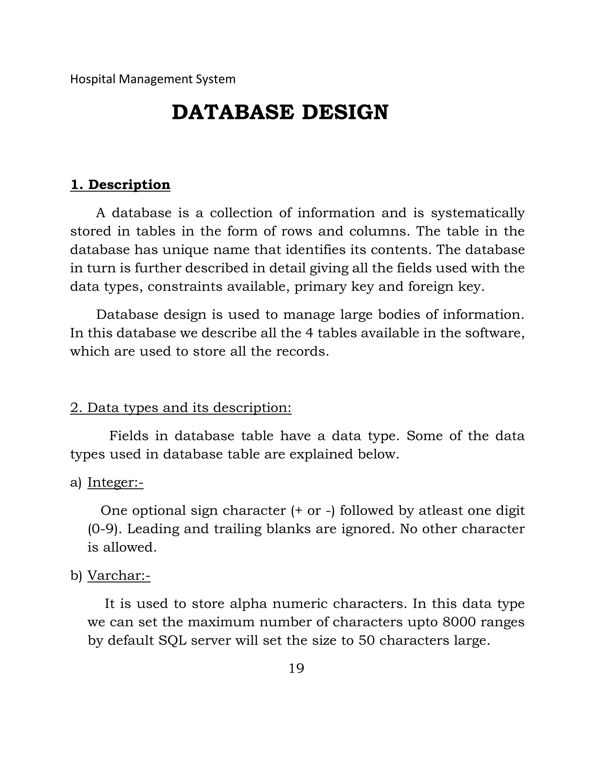
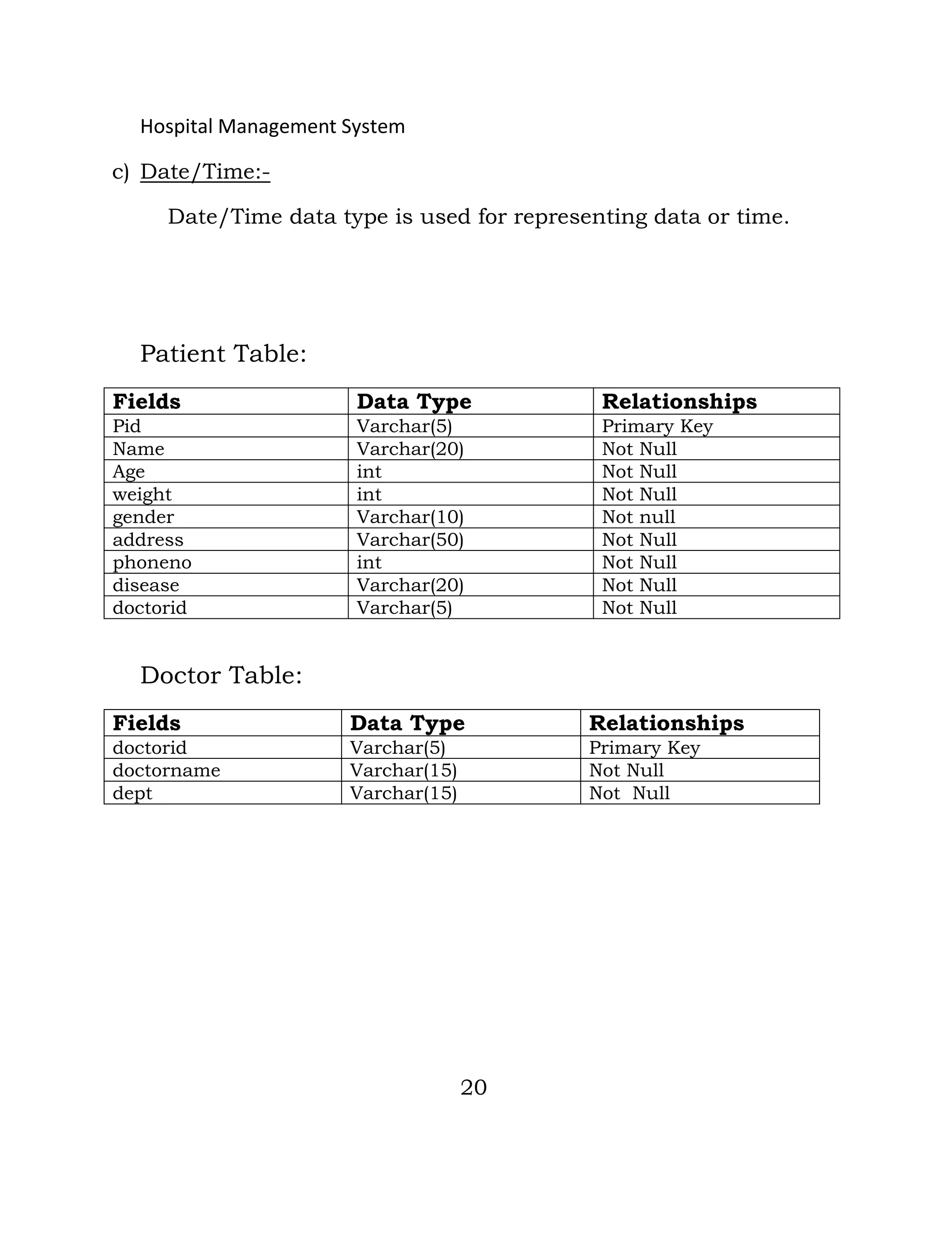
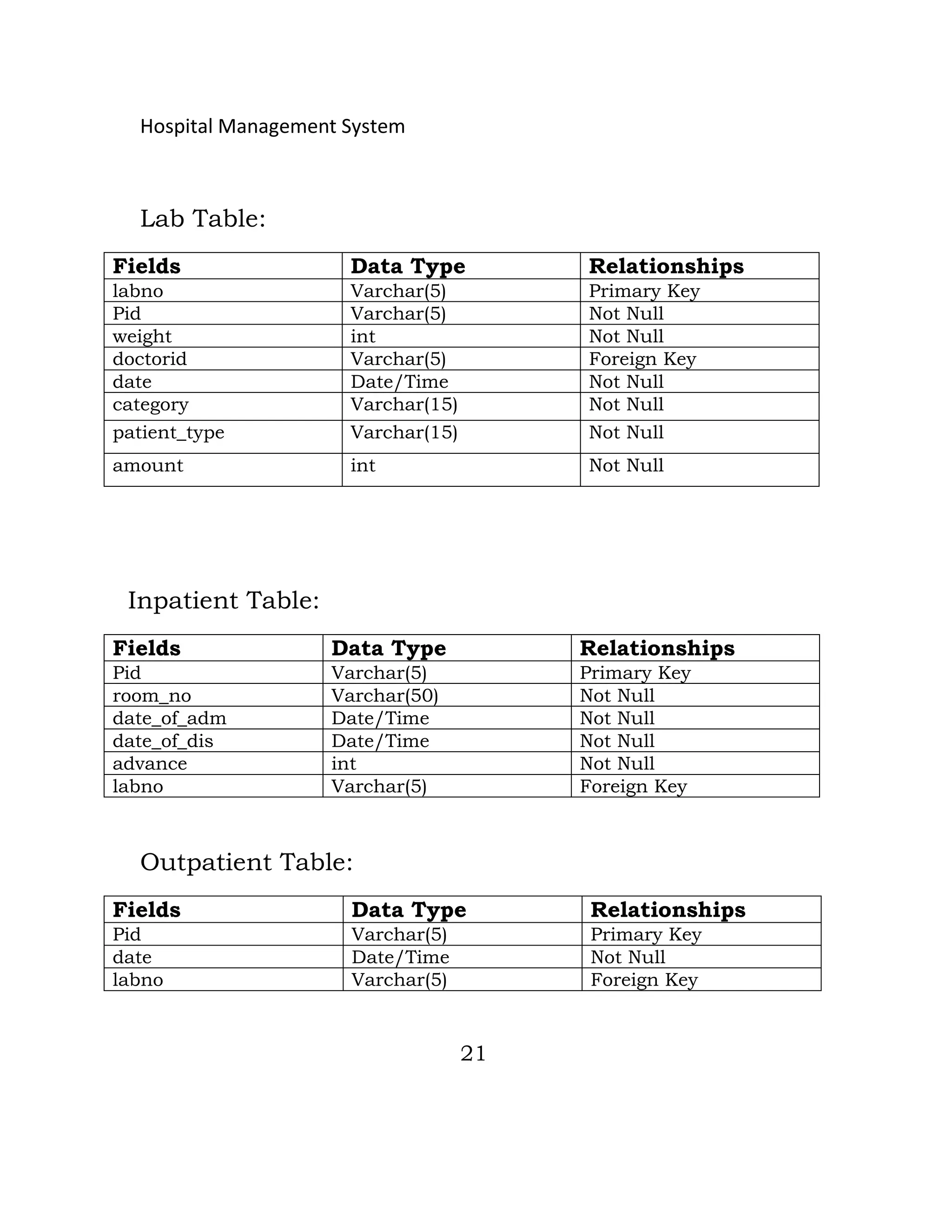
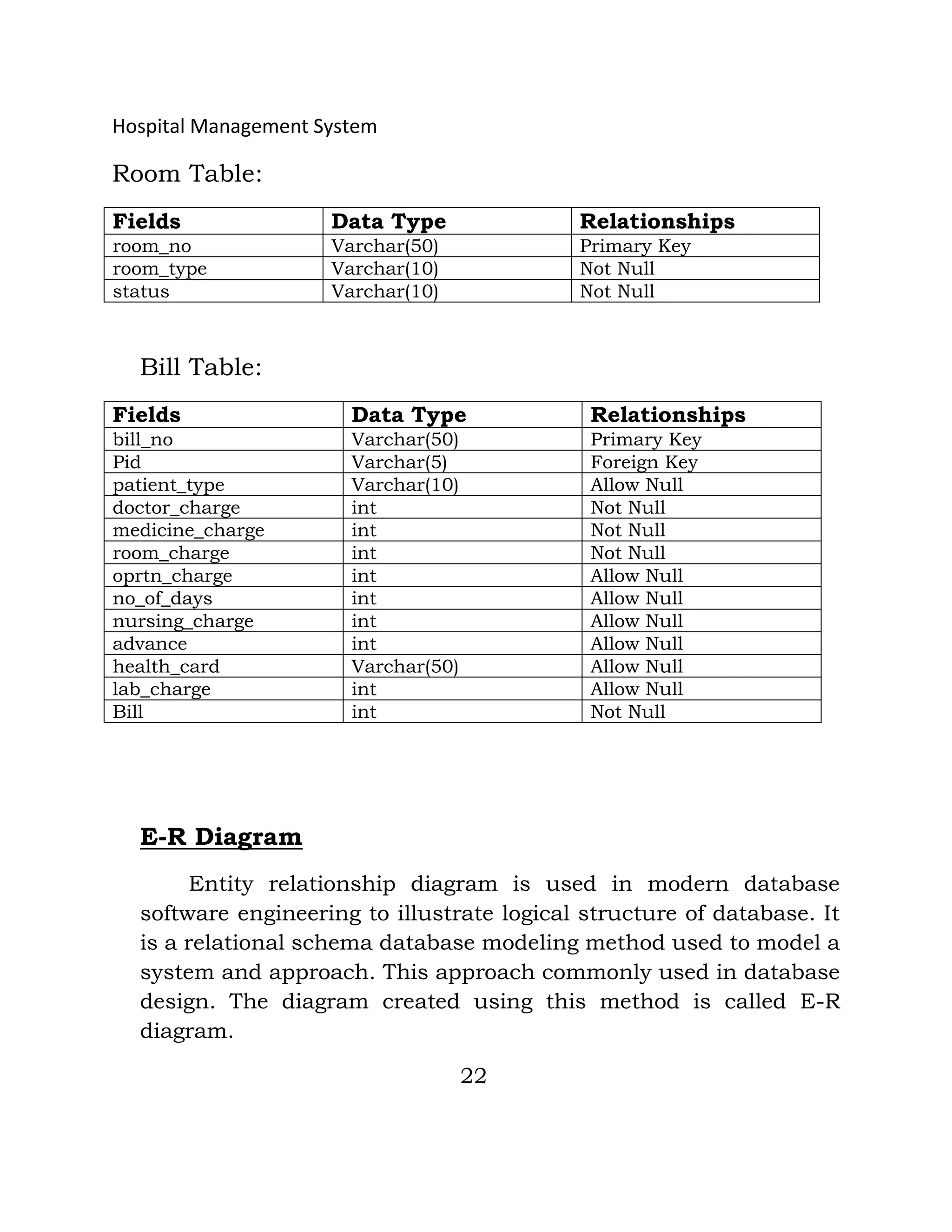
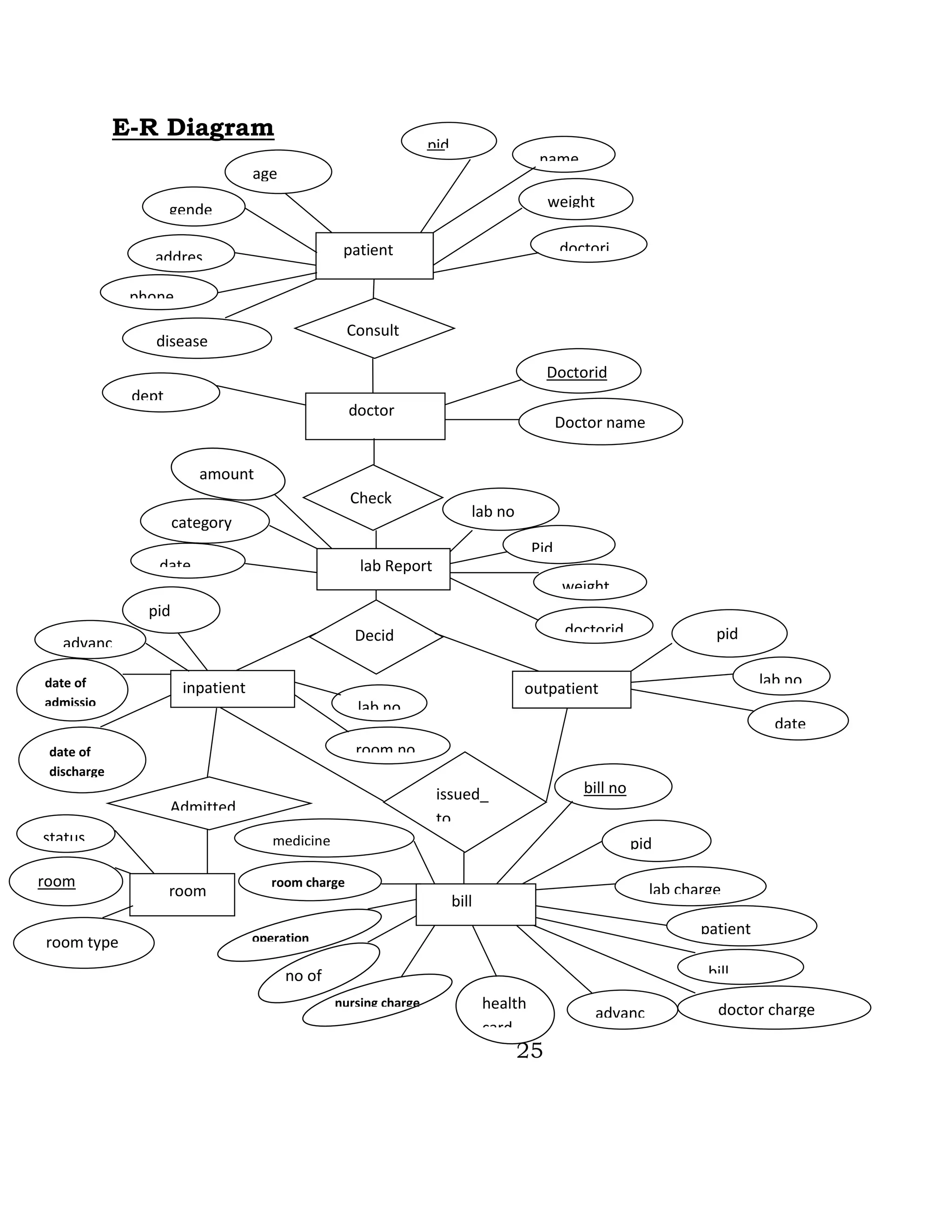
Hospital Management System
DATABASE DESIGN
1. Description
A database is a collection of information and is systematically
stored in tables in the form of rows and columns. The table in the
database has unique name that identifies its contents. The database
in turn is further described in detail giving all the fields used with the
data types, constraints available, primary key and foreign key.
Database design is used to manage large bodies of information.
In this database we describe all the 4 tables available in the software,
which are used to store all the records.
2. Data types and its description:
Fields in database table have a data type. Some of the data
types used in database table are explained below.
a) Integer:-
One optional sign character (+ or -) followed by atleast one digit
(0-9). Leading and trailing blanks are ignored. No other character
is allowed.
b) Varchar:-
It is used to store alpha numeric characters. In this data type
we can set the maximum number of characters upto 8000 ranges
by default SQL server will set the size to 50 characters large.
19
Hospital Management System
c) Date/Time:-
Date/Time data type is used for representing data or time.
Patient Table:
Fields Data Type Relationships
Pid Varchar(5) Primary Key
Name Varchar(20) Not Null
Age int Not Null
weight int Not Null
gender Varchar(10) Not null
address Varchar(50) Not Null
phoneno int Not Null
disease Varchar(20) Not Null
doctorid Varchar(5) Not Null
Doctor Table:
Fields Data Type Relationships
doctorid Varchar(5) Primary Key
doctorname Varchar(15) Not Null
dept Varchar(15) Not Null
20
Hospital Management System
Lab Table:
Fields Data Type Relationships
labno Varchar(5) Primary Key
Pid Varchar(5) Not Null
weight int Not Null
doctorid Varchar(5) Foreign Key
date Date/Time Not Null
category Varchar(15) Not Null
patient_type Varchar(15) Not Null
amount int Not Null
Inpatient Table:
Fields Data Type Relationships
Pid Varchar(5) Primary Key
room_no Varchar(50) Not Null
date_of_adm Date/Time Not Null
date_of_dis Date/Time Not Null
advance int Not Null
labno Varchar(5) Foreign Key
Outpatient Table:
Fields Data Type Relationships
Pid Varchar(5) Primary Key
date Date/Time Not Null
labno Varchar(5) Foreign Key
21
Hospital Management System
Room Table:
Fields Data Type Relationships
room_no Varchar(50) Primary Key
room_type Varchar(10) Not Null
status Varchar(10) Not Null
Bill Table:
Fields Data Type Relationships
bill_no Varchar(50) Primary Key
Pid Varchar(5) Foreign Key
patient_type Varchar(10) Allow Null
doctor_charge int Not Null
medicine_charge int Not Null
room_charge int Not Null
oprtn_charge int Allow Null
no_of_days int Allow Null
nursing_charge int Allow Null
advance int Allow Null
health_card Varchar(50) Allow Null
lab_charge int Allow Null
Bill int Not Null
E-R Diagram
Entity relationship diagram is used in modern database
software engineering to illustrate logical structure of database. It
is a relational schema database modeling method used to model a
system and approach. This approach commonly used in database
design. The diagram created using this method is called E-R
diagram.
22
Hospital Management System
The E-R diagram depicts the various relationships among
entities considering each object as entity. Entity is represented as
diamond shape and relationship is represented as rectangle. It
depicts the relationship between data objects. The E-R diagram is
the relation that is used to conduct the data modeling activity.
Entity:-
Entity is the thing which we want to store information. It is an
elementary basic building block of storing information about
business process. An entity represents an objects defined within
the information system about which you want to store information.
Relationship:-
A relationship is named connection or association between
entities used to relate two or more entities with some common
attributes of meaningful interaction between the object.
Attributes:-
Attributes are the properties of the entities and relationship.
Descriptor of the entity. Attributes are elementary pieces of
information attached to an entity.
23
Hospital Management System
Symbols Meaning
Entity
Relationship
Attribute
Key Attribute
Cardinality Ratio N: 1 for E1: E2
in R
24
Hospital Management System
E1 R E2
E-R Diagram
25
patient
pid
name
weight
doctori
d
gende
r
age
addres
s
phone
no
Consult
s
doctor
Doctorid
Doctor name
dept
Check
s
lab Report
lab no
Pid
weight
doctorid
date
category
Decid
es
inpatient outpatient
lab no
room no
pid
advanc
e
date of
admissio
n
date of
discharge
pid
lab no
date
Admitted
to to
room
status
room
no
room type
issued_
to
bill
bill no
pid
lab charge
patient
type
bill
doctor chargeadvanc
e
health
card
medicine
charge
room charge
operation
no of
nursing charge
disease
amount

Database design

  • 1.
    Hospital Management System DATABASEDESIGN 1. Description A database is a collection of information and is systematically stored in tables in the form of rows and columns. The table in the database has unique name that identifies its contents. The database in turn is further described in detail giving all the fields used with the data types, constraints available, primary key and foreign key. Database design is used to manage large bodies of information. In this database we describe all the 4 tables available in the software, which are used to store all the records. 2. Data types and its description: Fields in database table have a data type. Some of the data types used in database table are explained below. a) Integer:- One optional sign character (+ or -) followed by atleast one digit (0-9). Leading and trailing blanks are ignored. No other character is allowed. b) Varchar:- It is used to store alpha numeric characters. In this data type we can set the maximum number of characters upto 8000 ranges by default SQL server will set the size to 50 characters large. 19
  • 2.
    Hospital Management System c)Date/Time:- Date/Time data type is used for representing data or time. Patient Table: Fields Data Type Relationships Pid Varchar(5) Primary Key Name Varchar(20) Not Null Age int Not Null weight int Not Null gender Varchar(10) Not null address Varchar(50) Not Null phoneno int Not Null disease Varchar(20) Not Null doctorid Varchar(5) Not Null Doctor Table: Fields Data Type Relationships doctorid Varchar(5) Primary Key doctorname Varchar(15) Not Null dept Varchar(15) Not Null 20
  • 3.
    Hospital Management System LabTable: Fields Data Type Relationships labno Varchar(5) Primary Key Pid Varchar(5) Not Null weight int Not Null doctorid Varchar(5) Foreign Key date Date/Time Not Null category Varchar(15) Not Null patient_type Varchar(15) Not Null amount int Not Null Inpatient Table: Fields Data Type Relationships Pid Varchar(5) Primary Key room_no Varchar(50) Not Null date_of_adm Date/Time Not Null date_of_dis Date/Time Not Null advance int Not Null labno Varchar(5) Foreign Key Outpatient Table: Fields Data Type Relationships Pid Varchar(5) Primary Key date Date/Time Not Null labno Varchar(5) Foreign Key 21
  • 4.
    Hospital Management System RoomTable: Fields Data Type Relationships room_no Varchar(50) Primary Key room_type Varchar(10) Not Null status Varchar(10) Not Null Bill Table: Fields Data Type Relationships bill_no Varchar(50) Primary Key Pid Varchar(5) Foreign Key patient_type Varchar(10) Allow Null doctor_charge int Not Null medicine_charge int Not Null room_charge int Not Null oprtn_charge int Allow Null no_of_days int Allow Null nursing_charge int Allow Null advance int Allow Null health_card Varchar(50) Allow Null lab_charge int Allow Null Bill int Not Null E-R Diagram Entity relationship diagram is used in modern database software engineering to illustrate logical structure of database. It is a relational schema database modeling method used to model a system and approach. This approach commonly used in database design. The diagram created using this method is called E-R diagram. 22
  • 5.
    Hospital Management System TheE-R diagram depicts the various relationships among entities considering each object as entity. Entity is represented as diamond shape and relationship is represented as rectangle. It depicts the relationship between data objects. The E-R diagram is the relation that is used to conduct the data modeling activity. Entity:- Entity is the thing which we want to store information. It is an elementary basic building block of storing information about business process. An entity represents an objects defined within the information system about which you want to store information. Relationship:- A relationship is named connection or association between entities used to relate two or more entities with some common attributes of meaningful interaction between the object. Attributes:- Attributes are the properties of the entities and relationship. Descriptor of the entity. Attributes are elementary pieces of information attached to an entity. 23 Hospital Management System
  • 6.
    Symbols Meaning Entity Relationship Attribute Key Attribute CardinalityRatio N: 1 for E1: E2 in R 24 Hospital Management System E1 R E2
  • 7.
    E-R Diagram 25 patient pid name weight doctori d gende r age addres s phone no Consult s doctor Doctorid Doctor name dept Check s labReport lab no Pid weight doctorid date category Decid es inpatient outpatient lab no room no pid advanc e date of admissio n date of discharge pid lab no date Admitted to to room status room no room type issued_ to bill bill no pid lab charge patient type bill doctor chargeadvanc e health card medicine charge room charge operation no of nursing charge disease amount