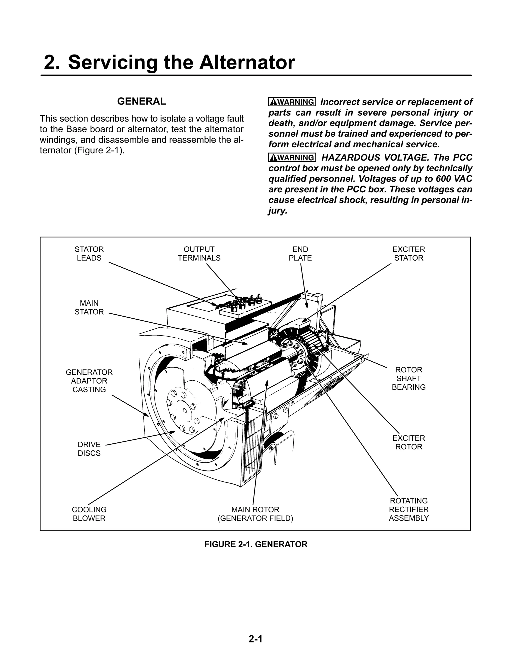
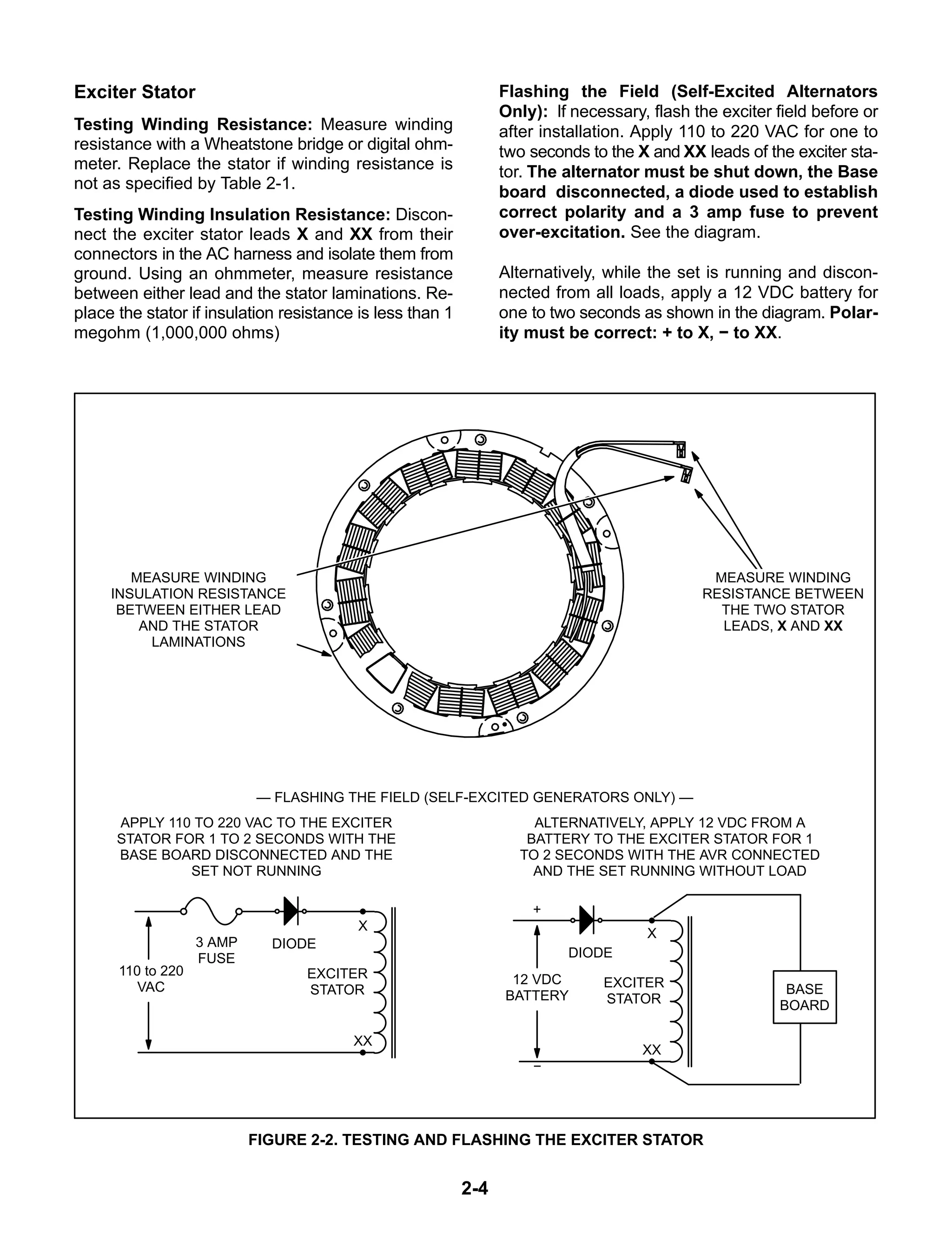
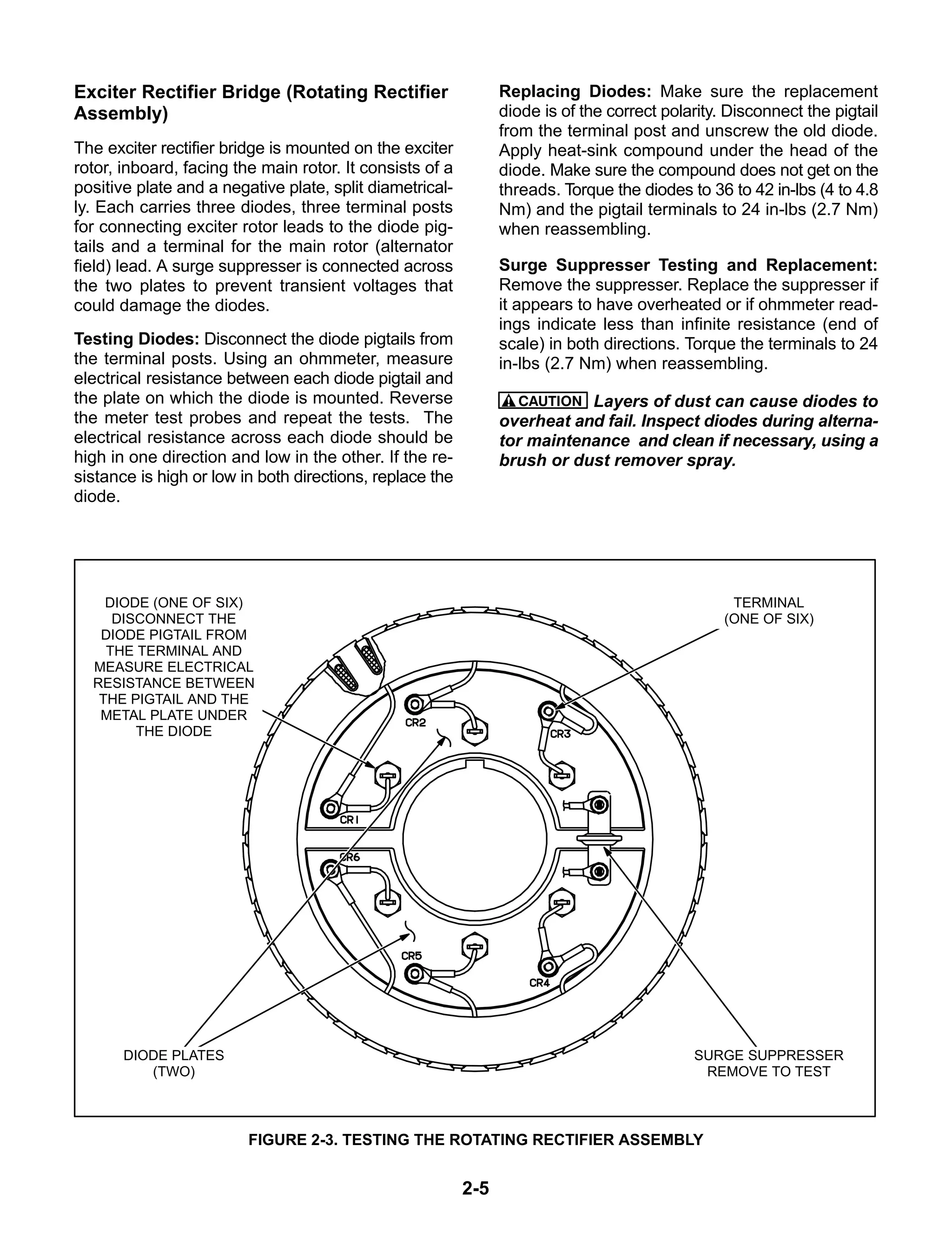
The document is a service manual that provides instructions for servicing the alternator on generator sets. It describes procedures for isolating faults to the alternator or base board, testing the alternator and its components, and disassembling and reassembling the alternator. Safety warnings are provided to alert technicians to hazardous conditions involving electricity, moving parts, exhaust and other hazards.
Why Is Your BMW X3 Hood Not Responding To Release CommandsDart Auto
Experiencing difficulty opening your BMW X3's hood? This guide explores potential issues like mechanical obstruction, hood release mechanism failure, electrical problems, and emergency release malfunctions. Troubleshooting tips include basic checks, clearing obstructions, applying pressure, and using the emergency release.
What Exactly Is The Common Rail Direct Injection System & How Does It WorkMotor Cars International
Learn about Common Rail Direct Injection (CRDi) - the revolutionary technology that has made diesel engines more efficient. Explore its workings, advantages like enhanced fuel efficiency and increased power output, along with drawbacks such as complexity and higher initial cost. Compare CRDi with traditional diesel engines and discover why it's the preferred choice for modern engines.
What Does the PARKTRONIC Inoperative, See Owner's Manual Message Mean for You...Autohaus Service and Sales
Learn what "PARKTRONIC Inoperative, See Owner's Manual" means for your Mercedes-Benz. This message indicates a malfunction in the parking assistance system, potentially due to sensor issues or electrical faults. Prompt attention is crucial to ensure safety and functionality. Follow steps outlined for diagnosis and repair in the owner's manual.
𝘼𝙣𝙩𝙞𝙦𝙪𝙚 𝙋𝙡𝙖𝙨𝙩𝙞𝙘 𝙏𝙧𝙖𝙙𝙚𝙧𝙨 𝙞𝙨 𝙫𝙚𝙧𝙮 𝙛𝙖𝙢𝙤𝙪𝙨 𝙛𝙤𝙧 𝙢𝙖𝙣𝙪𝙛𝙖𝙘𝙩𝙪𝙧𝙞𝙣𝙜 𝙩𝙝𝙚𝙞𝙧 𝙥𝙧𝙤𝙙𝙪𝙘𝙩𝙨. 𝙒𝙚 𝙝𝙖𝙫𝙚 𝙖𝙡𝙡 𝙩𝙝𝙚 𝙥𝙡𝙖𝙨𝙩𝙞𝙘 𝙜𝙧𝙖𝙣𝙪𝙡𝙚𝙨 𝙪𝙨𝙚𝙙 𝙞𝙣 𝙖𝙪𝙩𝙤𝙢𝙤𝙩𝙞𝙫𝙚 𝙖𝙣𝙙 𝙖𝙪𝙩𝙤 𝙥𝙖𝙧𝙩𝙨 𝙖𝙣𝙙 𝙖𝙡𝙡 𝙩𝙝𝙚 𝙛𝙖𝙢𝙤𝙪𝙨 𝙘𝙤𝙢𝙥𝙖𝙣𝙞𝙚𝙨 𝙗𝙪𝙮 𝙩𝙝𝙚 𝙜𝙧𝙖𝙣𝙪𝙡𝙚𝙨 𝙛𝙧𝙤𝙢 𝙪𝙨.
Over the 10 years, we have gained a strong foothold in the market due to our range's high quality, competitive prices, and time-lined delivery schedules.
Things to remember while upgrading the brakes of your carjennifermiller8137
Upgrading the brakes of your car? Keep these things in mind before doing so. Additionally, start using an OBD 2 GPS tracker so that you never miss a vehicle maintenance appointment. On top of this, a car GPS tracker will also let you master good driving habits that will let you increase the operational life of your car’s brakes.
"Trans Failsafe Prog" on your BMW X5 indicates potential transmission issues requiring immediate action. This safety feature activates in response to abnormalities like low fluid levels, leaks, faulty sensors, electrical or mechanical failures, and overheating.
Symptoms like intermittent starting and key recognition errors signal potential problems with your Mercedes’ EIS. Use diagnostic steps like error code checks and spare key tests. Professional diagnosis and solutions like EIS replacement ensure safe driving. Consult a qualified technician for accurate diagnosis and repair.
Comprehensive program for Agricultural Finance, the Automotive Sector, and Empowerment . We will define the full scope and provide a detailed two-week plan for identifying strategic partners in each area within Limpopo, including target areas.:
1. Agricultural : Supporting Primary and Secondary Agriculture
• Scope: Provide support solutions to enhance agricultural productivity and sustainability.
• Target Areas: Polokwane, Tzaneen, Thohoyandou, Makhado, and Giyani.
2. Automotive Sector: Partnerships with Mechanics and Panel Beater Shops
• Scope: Develop collaborations with automotive service providers to improve service quality and business operations.
• Target Areas: Polokwane, Lephalale, Mokopane, Phalaborwa, and Bela-Bela.
3. Empowerment : Focusing on Women Empowerment
• Scope: Provide business support support and training to women-owned businesses, promoting economic inclusion.
• Target Areas: Polokwane, Thohoyandou, Musina, Burgersfort, and Louis Trichardt.
We will also prioritize Industrial Economic Zone areas and their priorities.
Sign up on https://profilesmes.online/welcome/
To be eligible:
1. You must have a registered business and operate in Limpopo
2. Generate revenue
3. Sectors : Agriculture ( primary and secondary) and Automative
Women and Youth are encouraged to apply even if you don't fall in those sectors.
In this presentation, we have discussed a very important feature of BMW X5 cars… the Comfort Access. Things that can significantly limit its functionality. And things that you can try to restore the functionality of such a convenient feature of your vehicle.
5 Warning Signs Your BMW's Intelligent Battery Sensor Needs AttentionBertini's German Motors
IBS monitors and manages your BMW’s battery performance. If it malfunctions, you will have to deal with an array of electrical issues in your vehicle. Recognize warning signs like dimming headlights, frequent battery replacements, and electrical malfunctions to address potential IBS issues promptly.
Core technology of Hyundai Motor Group's EV platform 'E-GMP'Hyundai Motor Group
What’s the force behind Hyundai Motor Group's EV performance and quality?
Maximized driving performance and quick charging time through high-density battery pack and fast charging technology and applicable to various vehicle types!
Discover more about Hyundai Motor Group’s EV platform ‘E-GMP’!
What Does the Active Steering Malfunction Warning Mean for Your BMWTanner Motors
Discover the reasons why your BMW’s Active Steering malfunction warning might come on. From electrical glitches to mechanical failures and software anomalies, addressing these promptly with professional inspection and maintenance ensures continued safety and performance on the road, maintaining the integrity of your driving experience.
3. LS-16L
iii
IMPORTANT SAFETY INSTRUCTIONS
SAVE THESE INSTRUCTIONS − This manual contains
important instructions that should be followed during
installation and maintenance of the generator and batter-
ies.
Before operating the generator set (genset), read the
Operator’s Manual and become familiar with it and the
equipment. Safe and efficient operation can be
achieved only if the equipment is properly operated
and maintained. Many accidents are caused by failure
to follow fundamental rules and precautions.
The following symbols, found throughout this manual,
alert you to potentially dangerous conditions to the op-
erator, service personnel, or the equipment.
This symbol warns of immediate
hazards which will result in severe personal in-
jury or death.
WARNING This symbol refers to a hazard or un-
safe practice which can result in severe per-
sonal injury or death.
CAUTION This symbol refers to a hazard or un-
safe practice which can result in personal injury
or product or property damage.
FUEL AND FUMES ARE FLAMMABLE
Fire, explosion, and personal injury or death can result
from improper practices.
• DO NOT fill fuel tanks while engine is running, un-
less tanks are outside the engine compartment.
Fuel contact with hot engine or exhaust is a potential
fire hazard.
• DO NOT permit any flame, cigarette, pilot light,
spark, arcing equipment, or other ignition source
near the generator set or fuel tank.
• Fuel lines must be adequately secured and free of
leaks. Fuel connection at the engine should be
made with an approved flexible line. Do not use zinc
coated or copper fuel lines with diesel fuel.
• Be sure all fuel supplies have a positive shutoff
valve.
• Be sure battery area has been well-ventilated prior
to servicing near it. Lead-acid batteries emit a highly
explosive hydrogen gas that can be ignited by arc-
ing, sparking, smoking, etc.
EXHAUST GASES ARE DEADLY
• Provide an adequate exhaust system to properly
expel discharged gases away from enclosed or
sheltered areas and areas where individuals are
likely to congregate. Visually and audibly inspect
the exhaust daily for leaks per the maintenance
schedule. Make sure that exhaust manifolds are se-
cured and not warped. Do not use exhaust gases to
heat a compartment.
• Be sure the unit is well ventilated.
• Engine exhaust and some of its constituents are
known to the state of California to cause cancer,
birth defects, and other reproductive harm.
MOVING PARTS CAN CAUSE SEVERE
PERSONAL INJURY OR DEATH
• Keep your hands, clothing, and jewelry away from
moving parts.
• Before starting work on the generator set, discon-
nect battery charger from its AC source, then dis-
connect starting batteries, negative (−) cable first.
This will prevent accidental starting.
• Make sure that fasteners on the generator set are
secure. Tighten supports and clamps, keep guards
in position over fans, drive belts, etc.
• Do not wear loose clothing or jewelry in the vicinity of
moving parts, or while working on electrical equip-
ment. Loose clothing and jewelry can become
caught in moving parts.
• If adjustment must be made while the unit is run-
ning, use extreme caution around hot manifolds,
moving parts, etc.
DO NOT OPERATE IN FLAMMABLE AND
EXPLOSIVE ENVIRONMENTS
Flammable vapor can cause an engine to overspeed and
become difficult to stop, resulting in possible fire, explo-
sion, severe personal injury and death. Do not operate a
genset where a flammable vapor environment can be
created by fuel spill, leak, etc., unless the genset is
equipped with an automatic safety device to block the air
intake and stop the engine. The owners and operators of
the genset are solely responsible for operating the gen-
set safely. Contact your authorized Cummins Power
Generation distributor for more information.
4. iv
ELECTRICAL SHOCK CAN CAUSE
SEVERE PERSONAL INJURY OR DEATH
• Remove electric power before removing protective
shields or touching electrical equipment. Use rub-
ber insulative mats placed on dry wood platforms
over floors that are metal or concrete when around
electrical equipment. Do not wear damp clothing
(particularly wet shoes) or allow skin surface to be
damp when handling electrical equipment. Do not
wear jewelry. Jewelry can short out electrical con-
tacts and cause shock or burning.
• Use extreme caution when working on electrical
components. High voltages can cause injury or
death. DO NOT tamper with interlocks.
• Follow all applicable state and local electrical
codes. Have all electrical installations performed by
a qualified licensed electrician. Tag and lock open
switches to avoid accidental closure.
• DO NOT CONNECT GENERATOR SET DI-
RECTLY TO ANY BUILDING ELECTRICAL SYS-
TEM. Hazardous voltages can flow from the gen-
erator set into the utility line. This creates a potential
for electrocution or property damage. Connect only
through an approved isolation switch or an ap-
proved paralleling device.
GENERAL SAFETY PRECAUTIONS
• Coolants under pressure have a higher boiling point
than water. DO NOT open a radiator or heat ex-
changer pressure cap while the engine is running.
To prevent severe scalding, let engine cool down
before removing coolant pressure cap. Turn cap
slowly, and do not open it fully until the pressure has
been relieved.
• Used engine oils have been identified by some state
or federal agencies as causing cancer or reproduc-
tive toxicity. When checking or changing engine oil,
take care not to ingest, breathe the fumes, or con-
tact used oil.
• Keep multi-class ABC fire extinguishers handy.
Class A fires involve ordinary combustible materials
such as wood and cloth; Class B fires, combustible
and flammable liquid fuels and gaseous fuels; Class
C fires, live electrical equipment. (ref. NFPA No. 10).
• Make sure that rags or combustible material are not
left on or near the generator set.
• Make sure generator set is mounted in a manner to
prevent combustible materials from accumulating
under or near the unit.
• Remove all unnecessary grease and oil from the
unit. Accumulated grease and oil can cause over-
heating and engine damage which present a poten-
tial fire hazard.
• Keep the generator set and the surrounding area
clean and free from obstructions. Remove any de-
bris from the set and keep the floor clean and dry.
• Do not work on this equipment when mentally or
physically fatigued, or after consuming any alcohol
or drug that makes the operation of equipment un-
safe.
• Substances in exhaust gases have been identified
by some state or federal agencies as causing can-
cer or reproductive toxicity. Take care not to breath
or ingest or come into contact with exhaust gases.
• Do not store any flammable liquids, such as fuel,
cleaners, oil, etc., near the generator set. A fire or
explosion could result.
• Wear hearing protection when near an operating
generator set.
• To prevent serious burns, avoid contact with hot
metal parts such as radiator system, turbo charger
system and exhaust system.
KEEP THIS MANUAL NEAR THE GENSET FOR EASY REFERENCE
6. 2-1
2. Servicing the Alternator
GENERAL
This section describes how to isolate a voltage fault
to the Base board or alternator, test the alternator
windings, and disassemble and reassemble the al-
ternator (Figure 2-1).
WARNING Incorrect service or replacement of
parts can result in severe personal injury or
death, and/or equipment damage. Service per-
sonnel must be trained and experienced to per-
form electrical and mechanical service.
WARNING HAZARDOUS VOLTAGE. The PCC
control box must be opened only by technically
qualified personnel. Voltages of up to 600 VAC
are present in the PCC box. These voltages can
cause electrical shock, resulting in personal in-
jury.
OUTPUT
TERMINALS
END
PLATE
EXCITER
STATOR
DRIVE
DISCS
MAIN ROTOR
(GENERATOR FIELD)
ROTATING
RECTIFIER
ASSEMBLY
EXCITER
ROTOR
ROTOR
SHAFT
BEARING
COOLING
BLOWER
STATOR
LEADS
GENERATOR
ADAPTOR
CASTING
MAIN
STATOR
FIGURE 2-1. GENERATOR
7. 2-2
ALTERNATOR/BASE BOARD ISOLATION
PROCEDURE
The following procedure is used to determine if the
alternator or the control Base board is causing a
high AC voltage shutdown fault.
1. Throw the line circuit breaker OFF and shut
down the set.
CAUTION This test involves unregulated
excitation of the alternator. To prevent dam-
age to the alternator due to overcurrent,
make sure that all loads have been discon-
nected and that all faults have been cleared
from the power output terminals of the al-
ternator.
WARNING HAZARDOUS VOLTAGE.
Touching uninsulated parts inside the con-
trol housing and power output boxes can
result in severe personal injury or death.
Measurements and adjustments must be
done with care to avoid touching hazard-
ous voltage parts.
Stand on a dry wooden platform or rubber
insulating mat, make sure your clothing
and shoes are dry, remove jewelry and use
tools with insulated handles.
2. Remove the top cover of the terminal box to ac-
cess the exciter stator leads (X and XX). Dis-
connect the X and XX leads from the AC har-
ness (quick connect type connectors).
3. Prepare to measure output voltage across the
alternator terminals while the set is running.
4. Bring two jumpers from a 12 volt battery for
connection to the excitor stator X (Field +) and
XX (Field −) leads.
Connect the jumper from the positive (+) post
of the battery to the X lead. Be prepared to con-
nect the jumper from the negative (−) post of
the battery to the XX lead.
5. Check polarity again. Polarity must be correct
or this test will be inconclusive because the in-
duced and residual magnetic polarities in the
exciter stator will be opposed.
Genset may shut down on a fault condition with-
in 5 to 15 seconds due to the excitor stator leads
being disconnected from the Base board. Clear
fault and start genset to check next phase.
6. Start the set and connect the jumper from the
battery negative (−) terminal to the XX lead.
7. The alternator circuitry is probably okay if rated
output voltage or higher is obtained and the
voltages for all phases are balanced when the
exciter is powered by a 12 volt battery.
8. If the voltages are unbalanced, troubleshoot
the main stator first. If the voltages are uniform-
ly low, troubleshoot the exciter and field circuits
first. Perform the Winding Resistance Test pro-
cedure for the desired windings as noted in this
section.
8. 2-3
TESTING THE ALTERNATOR
These tests can be performed without disassem-
bling the alternator. Before starting tests, discon-
nect the negative (−) cable from the battery to make
sure the engine will not start while performing these
tests.
CAUTION Before disconnecting battery
cable(s), press the Emergency Stop button and
wait at least 30 seconds. Fault code 1117 may
display and engine performance may be af-
fected (e.g., engine dying or hard starting) if bat-
tery cable(s) is removed during the 30 second
waiting period. See fault code 1117 in Section 4
to reset ECM.
WARNING Ignition of explosive battery gases
can cause severe personal injury or death. Arc-
ing at battery terminals, light switch or other
equipment, flame, pilot lights and sparks can ig-
nite battery gas. Do not smoke, or switch
trouble light ON or OFF near battery. Discharge
static electricity from body before touching bat-
teries by first touching a grounded metal sur-
face.
Ventilate battery area before working on or near
battery—Wear goggles—Stop genset and dis-
connect charger before disconnecting battery
cables—Disconnect negative (−) cable first and
reconnect last.
CAUTION Disconnect battery charger from AC
source before disconnecting battery cables.
Otherwise, disconnecting cables can result in
voltage spikes damaging to DC control circuits
of the set.
WARNING Accidental starting of the generator
set can cause severe personal injury or death.
Prevent accidental starting by disconnecting
the negative (−) cable from the battery terminal.
Before starting tests, disconnect the negative (−)
cable from the battery to make sure the set will not
start while working on it.
1. Press the button to switch to the Off mode.
2. Turn off or remove AC power from the battery
charger.
3. Press the Emergency Stop button and wait at
least 30 seconds before completing Step 4.
4. Remove the negative (−) battery cable from the
generator set starting battery.
Insulation Resistance Testing
The insulation resistance test should be performed
when low winding insulation is suspected, e.g.
damp or wet windings.
A 500 VAC megger is recommended for insulation
testing. A test consists of applying the test potential
between the winding and ground (winding lamina-
tions).
Resistance values of at least 5 megohms should be
obtained for a new alternator with dry windings. For
a alternator that has been in service, the resistance
reading should not be less than 1 megohm.
If low readings are obtained, the cause should be in-
vestigated and corrected before the generator set is
returned to service.
If moisture is determined to be the cause of low test
readings, a winding drying process will be required.
Megger Testing:
1. Disconnect plugs P12, P18, and P22 from the
Base board.
2. If the RTD (resistive thermal device) option is
installed, ground all six RTD temperature
leads. Each RTD has three leads, one red and
two white leads. Total of 18 leads must be
grounded. Refer to Customer Connections
Diagram in Section 3.
3. Perform the Insulation Resistance Test proce-
dure for the desired windings as noted in this
section.
Drying the Windings: If low readings are obtained
or the set has been in standby for a long time in high
humidity conditions, the windings should be dried
out and the test repeated. Use the alternator heat-
ers (if so equipped) or blow warm air through the al-
ternator from front (exciter end) to back with a fan.
9. 2-4
Exciter Stator
Testing Winding Resistance: Measure winding
resistance with a Wheatstone bridge or digital ohm-
meter. Replace the stator if winding resistance is
not as specified by Table 2-1.
Testing Winding Insulation Resistance: Discon-
nect the exciter stator leads X and XX from their
connectors in the AC harness and isolate them from
ground. Using an ohmmeter, measure resistance
between either lead and the stator laminations. Re-
place the stator if insulation resistance is less than 1
megohm (1,000,000 ohms)
Flashing the Field (Self-Excited Alternators
Only): If necessary, flash the exciter field before or
after installation. Apply 110 to 220 VAC for one to
two seconds to the X and XX leads of the exciter sta-
tor. The alternator must be shut down, the Base
board disconnected, a diode used to establish
correct polarity and a 3 amp fuse to prevent
over-excitation. See the diagram.
Alternatively, while the set is running and discon-
nected from all loads, apply a 12 VDC battery for
one to two seconds as shown in the diagram. Polar-
ity must be correct: + to X, − to XX.
MEASURE WINDING
INSULATION RESISTANCE
BETWEEN EITHER LEAD
AND THE STATOR
LAMINATIONS
MEASURE WINDING
RESISTANCE BETWEEN
THE TWO STATOR
LEADS, X AND XX
X
XX
110 to 220
VAC
DIODE
EXCITER
STATOR
APPLY 110 TO 220 VAC TO THE EXCITER
STATOR FOR 1 TO 2 SECONDS WITH THE
BASE BOARD DISCONNECTED AND THE
SET NOT RUNNING
3 AMP
FUSE
X
XX
12 VDC
BATTERY
DIODE
EXCITER
STATOR
ALTERNATIVELY, APPLY 12 VDC FROM A
BATTERY TO THE EXCITER STATOR FOR 1
TO 2 SECONDS WITH THE AVR CONNECTED
AND THE SET RUNNING WITHOUT LOAD
+
−
BASE
BOARD
— FLASHING THE FIELD (SELF-EXCITED GENERATORS ONLY) —
FIGURE 2-2. TESTING AND FLASHING THE EXCITER STATOR
10. 2-5
Exciter Rectifier Bridge (Rotating Rectifier
Assembly)
The exciter rectifier bridge is mounted on the exciter
rotor, inboard, facing the main rotor. It consists of a
positive plate and a negative plate, split diametrical-
ly. Each carries three diodes, three terminal posts
for connecting exciter rotor leads to the diode pig-
tails and a terminal for the main rotor (alternator
field) lead. A surge suppresser is connected across
the two plates to prevent transient voltages that
could damage the diodes.
Testing Diodes: Disconnect the diode pigtails from
the terminal posts. Using an ohmmeter, measure
electrical resistance between each diode pigtail and
the plate on which the diode is mounted. Reverse
the meter test probes and repeat the tests. The
electrical resistance across each diode should be
high in one direction and low in the other. If the re-
sistance is high or low in both directions, replace the
diode.
Replacing Diodes: Make sure the replacement
diode is of the correct polarity. Disconnect the pigtail
from the terminal post and unscrew the old diode.
Apply heat-sink compound under the head of the
diode. Make sure the compound does not get on the
threads. Torque the diodes to 36 to 42 in-lbs (4 to 4.8
Nm) and the pigtail terminals to 24 in-lbs (2.7 Nm)
when reassembling.
Surge Suppresser Testing and Replacement:
Remove the suppresser. Replace the suppresser if
it appears to have overheated or if ohmmeter read-
ings indicate less than infinite resistance (end of
scale) in both directions. Torque the terminals to 24
in-lbs (2.7 Nm) when reassembling.
CAUTION Layers of dust can cause diodes to
overheat and fail. Inspect diodes during alterna-
tor maintenance and clean if necessary, using a
brush or dust remover spray.
TERMINAL
(ONE OF SIX)
DIODE (ONE OF SIX)
DISCONNECT THE
DIODE PIGTAIL FROM
THE TERMINAL AND
MEASURE ELECTRICAL
RESISTANCE BETWEEN
THE PIGTAIL AND THE
METAL PLATE UNDER
THE DIODE
SURGE SUPPRESSER
REMOVE TO TEST
DIODE PLATES
(TWO)
FIGURE 2-3. TESTING THE ROTATING RECTIFIER ASSEMBLY
11. Thank you very much
for your reading.
Please Click Here
Then Get More
Information.