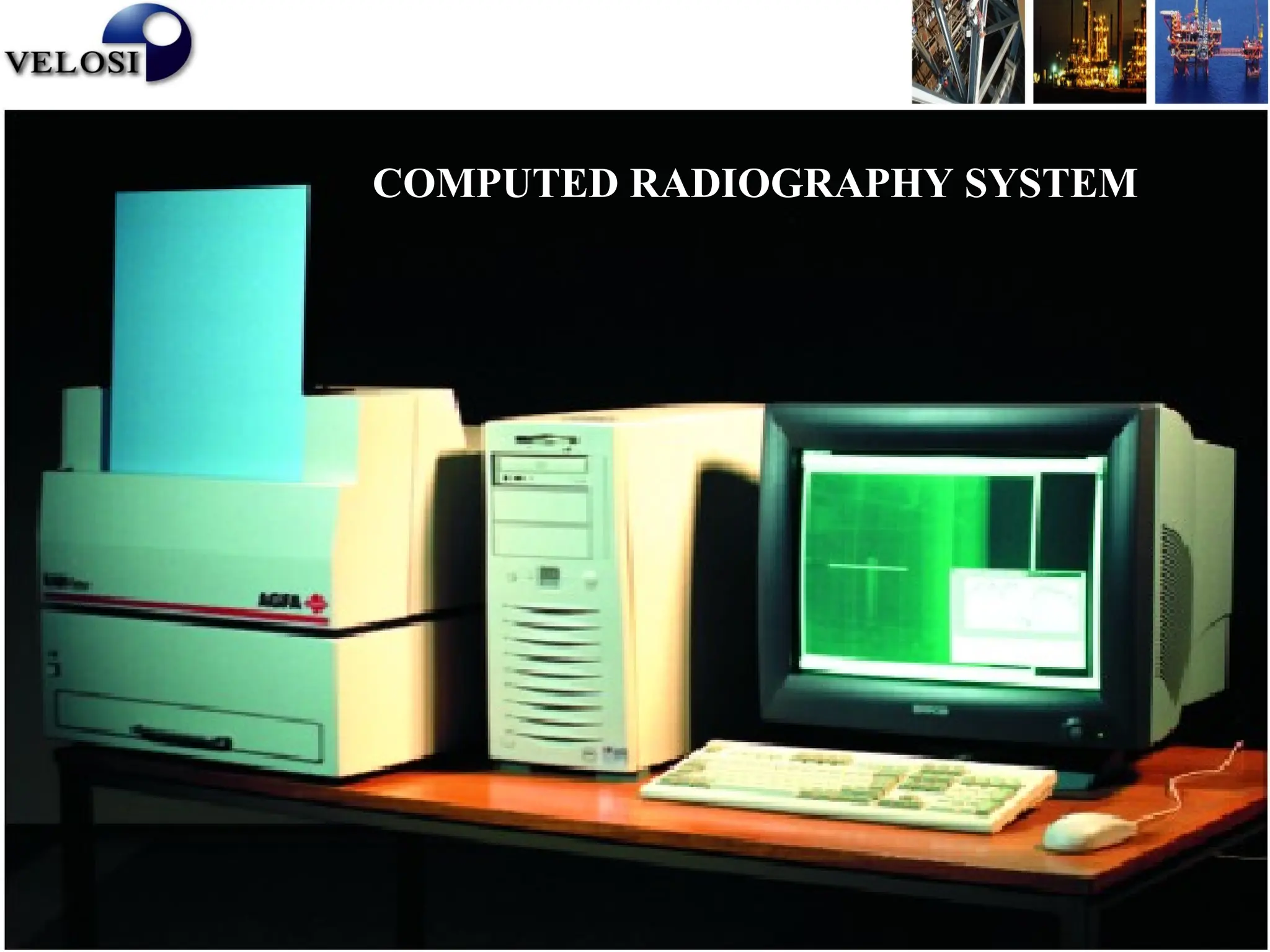
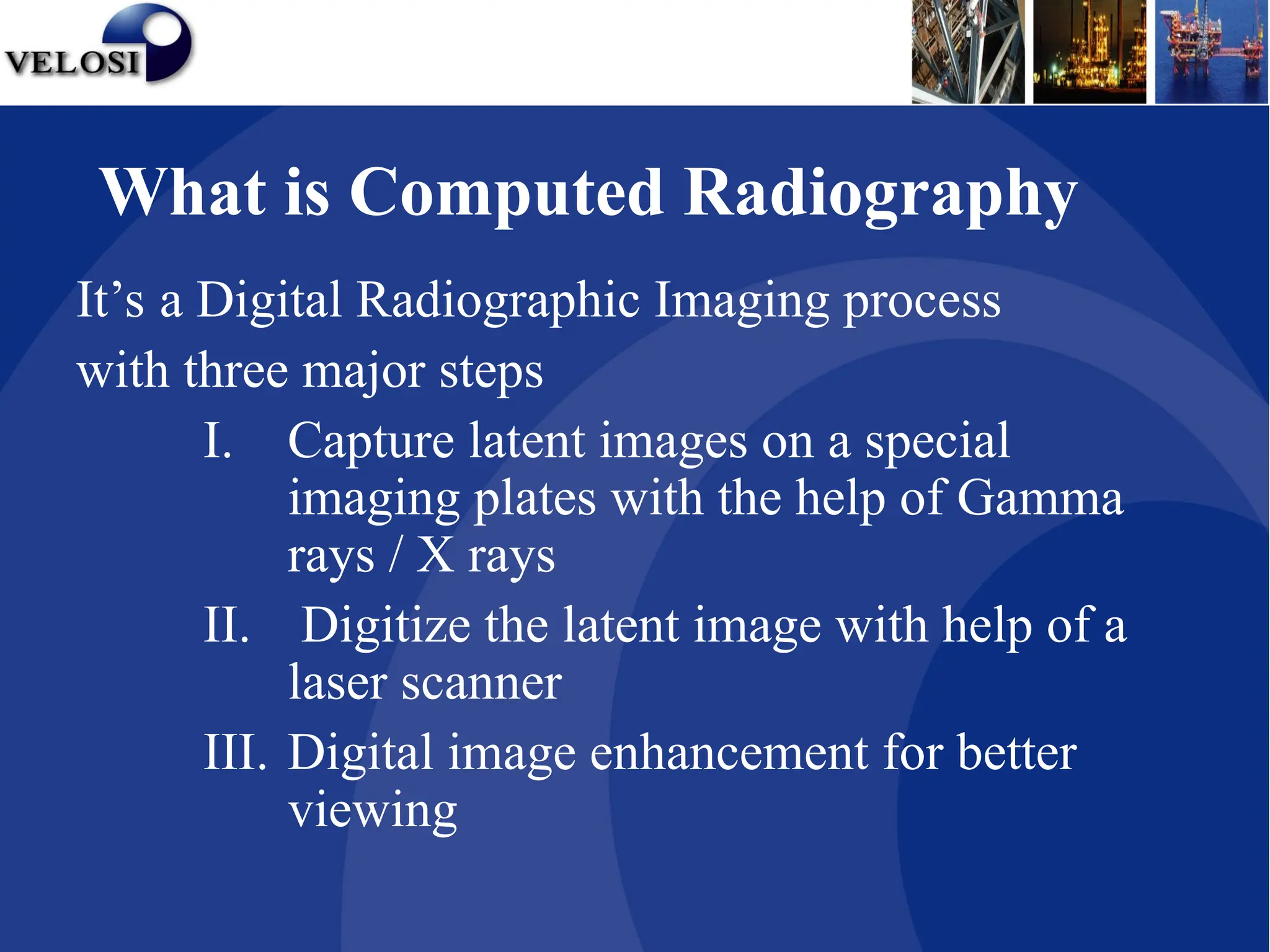
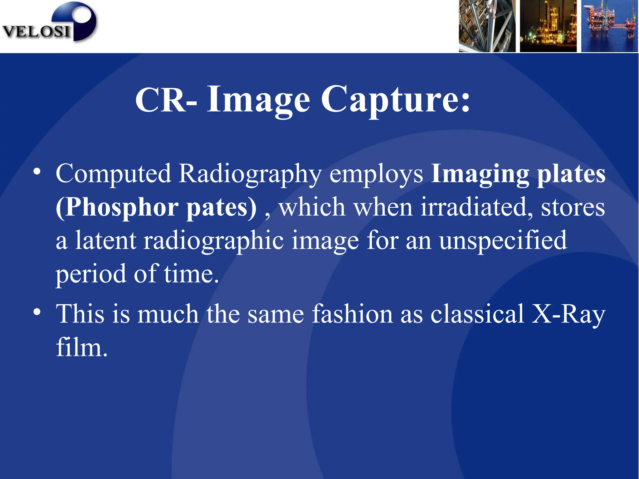
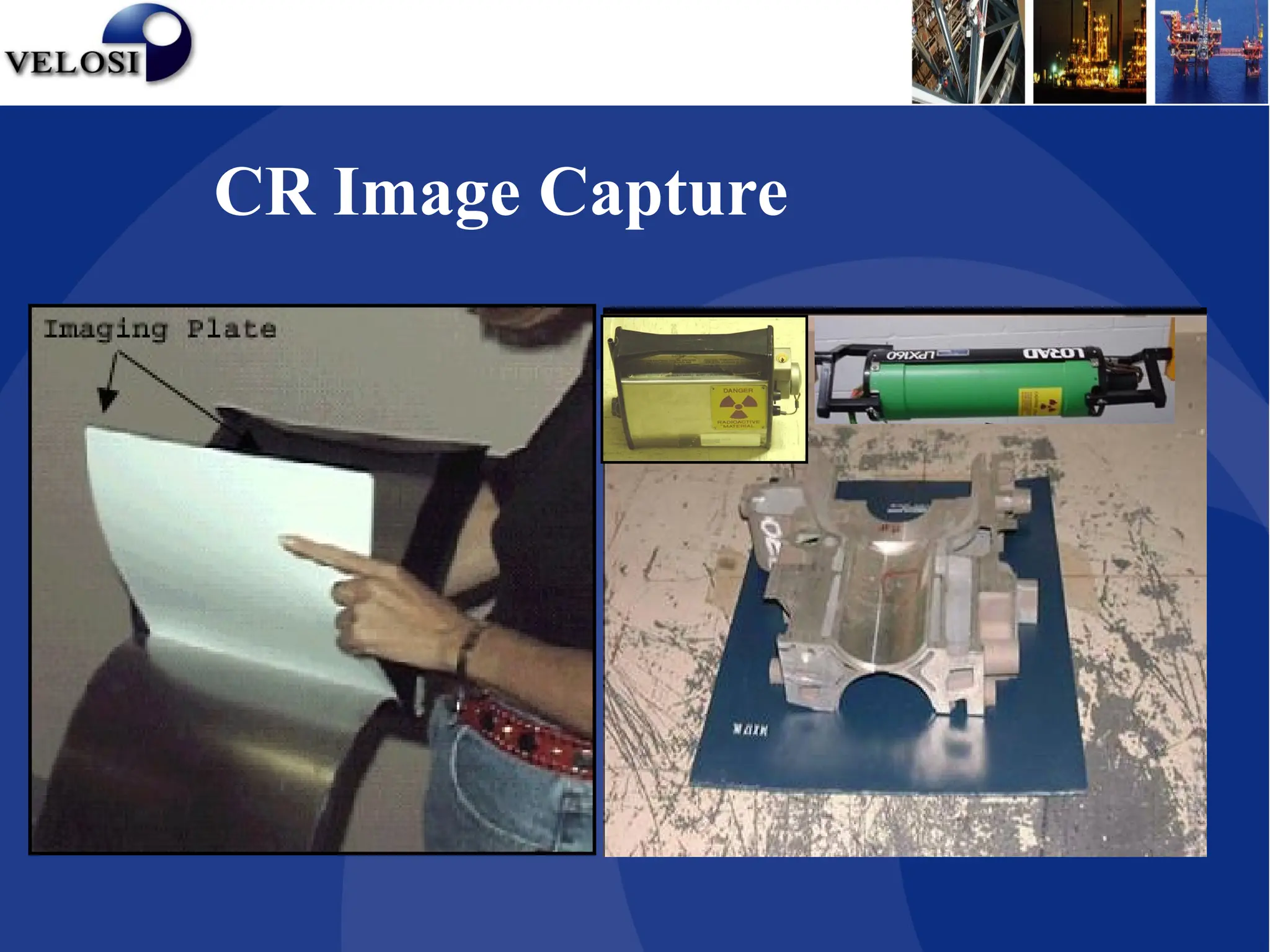
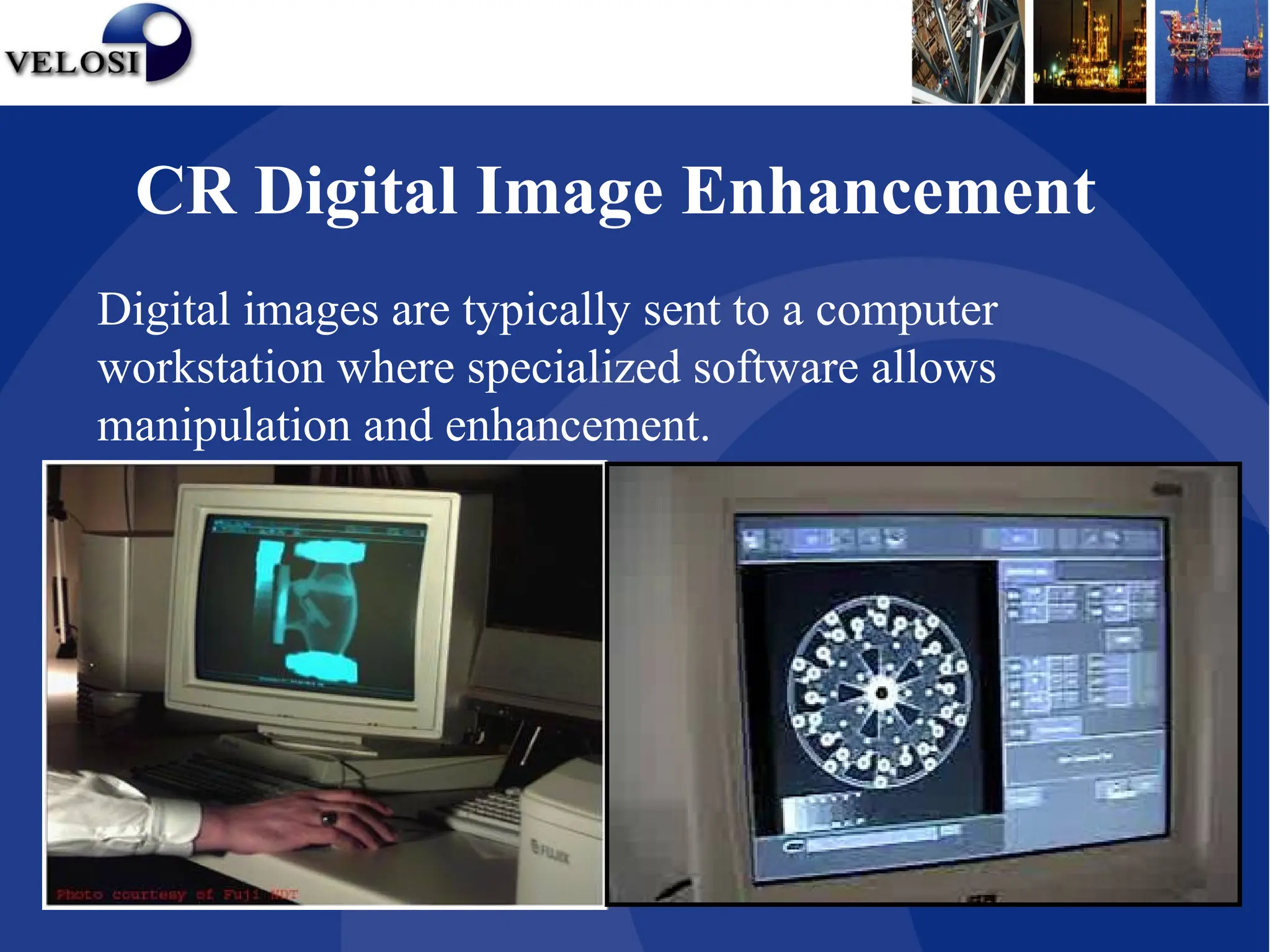
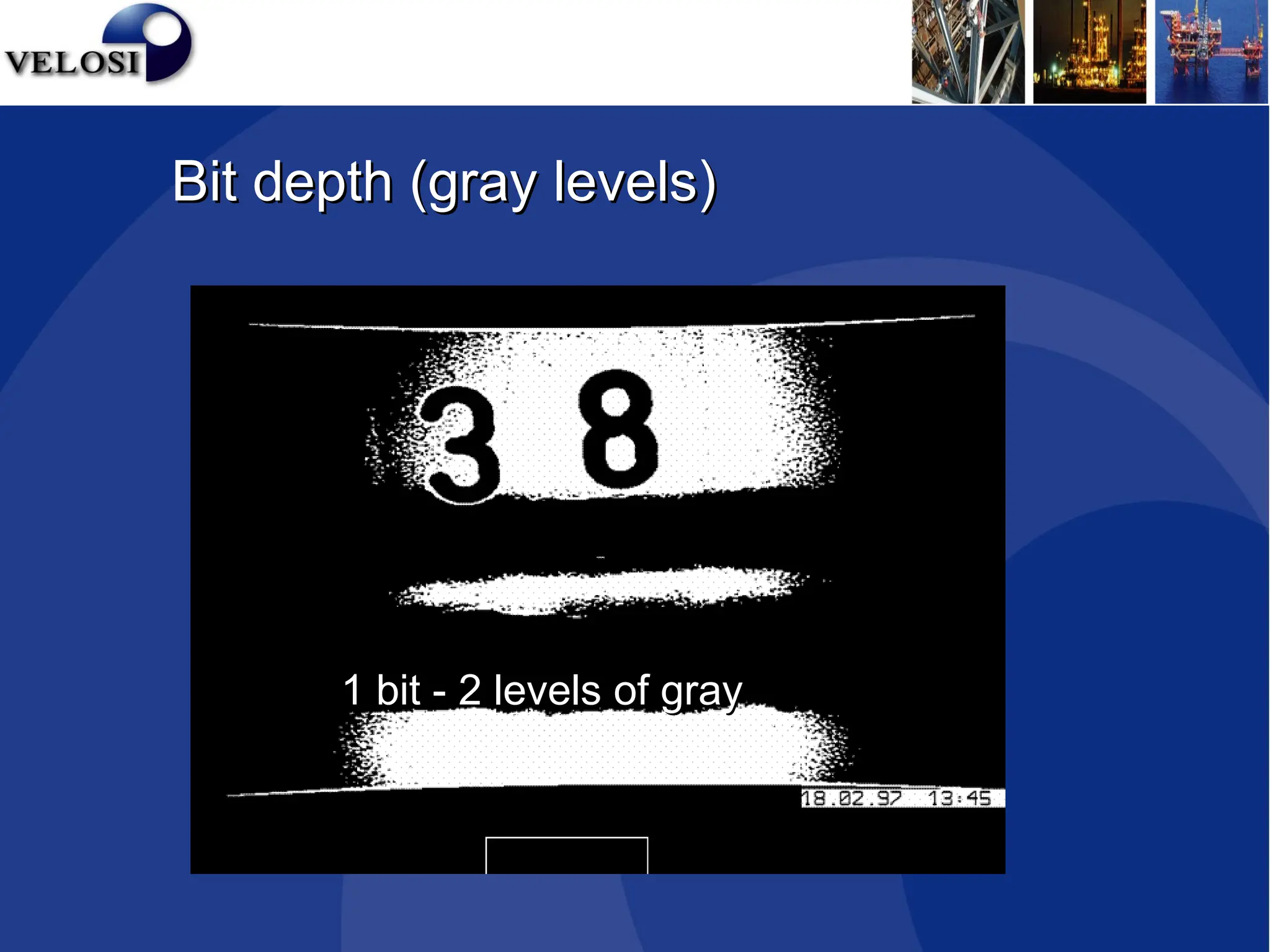
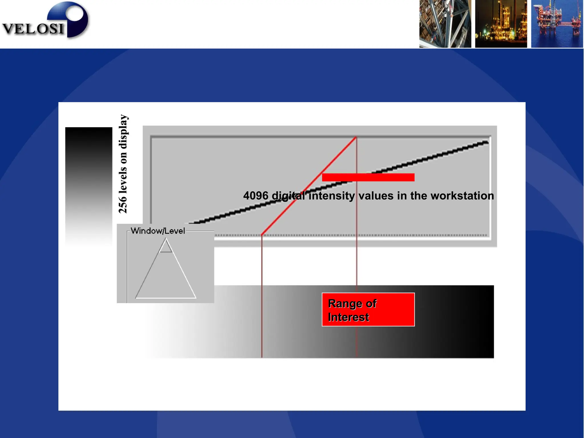
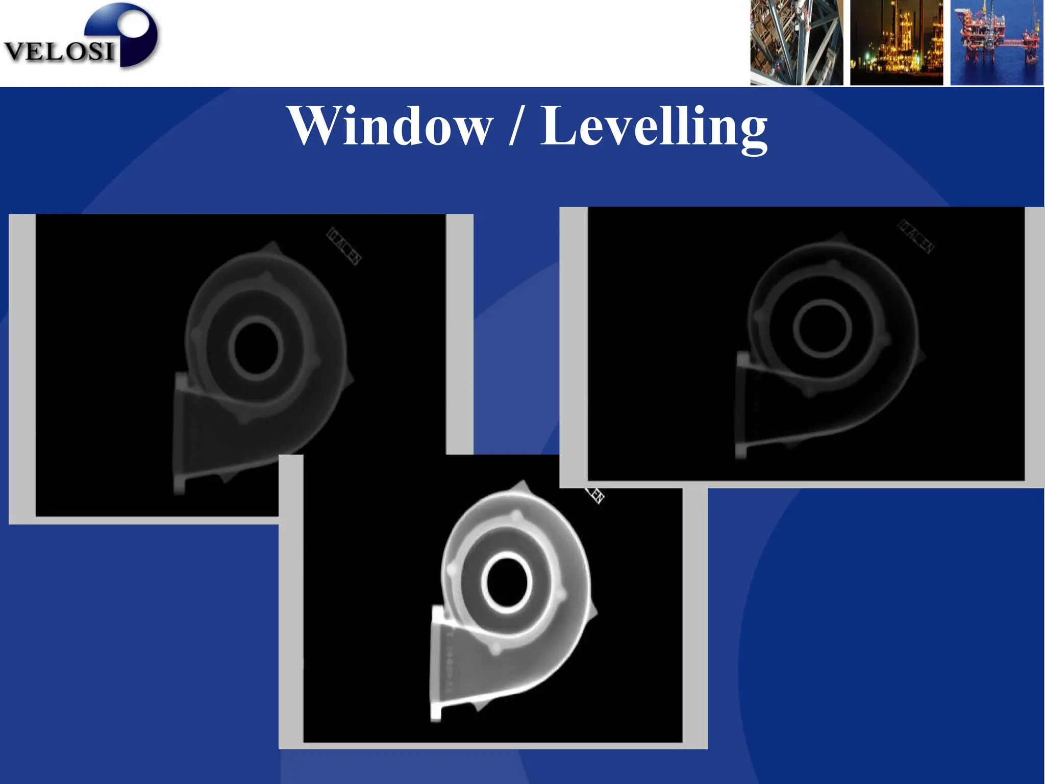
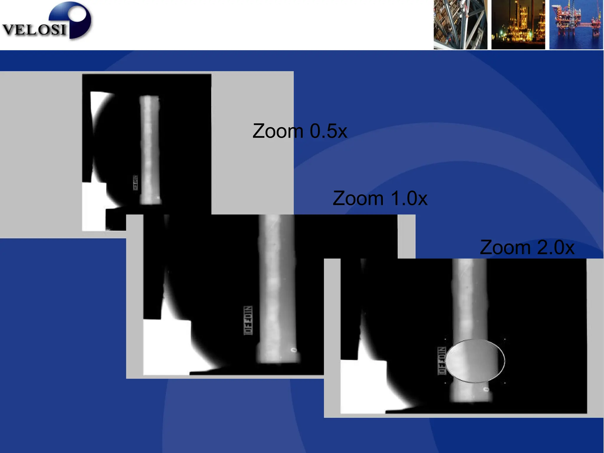
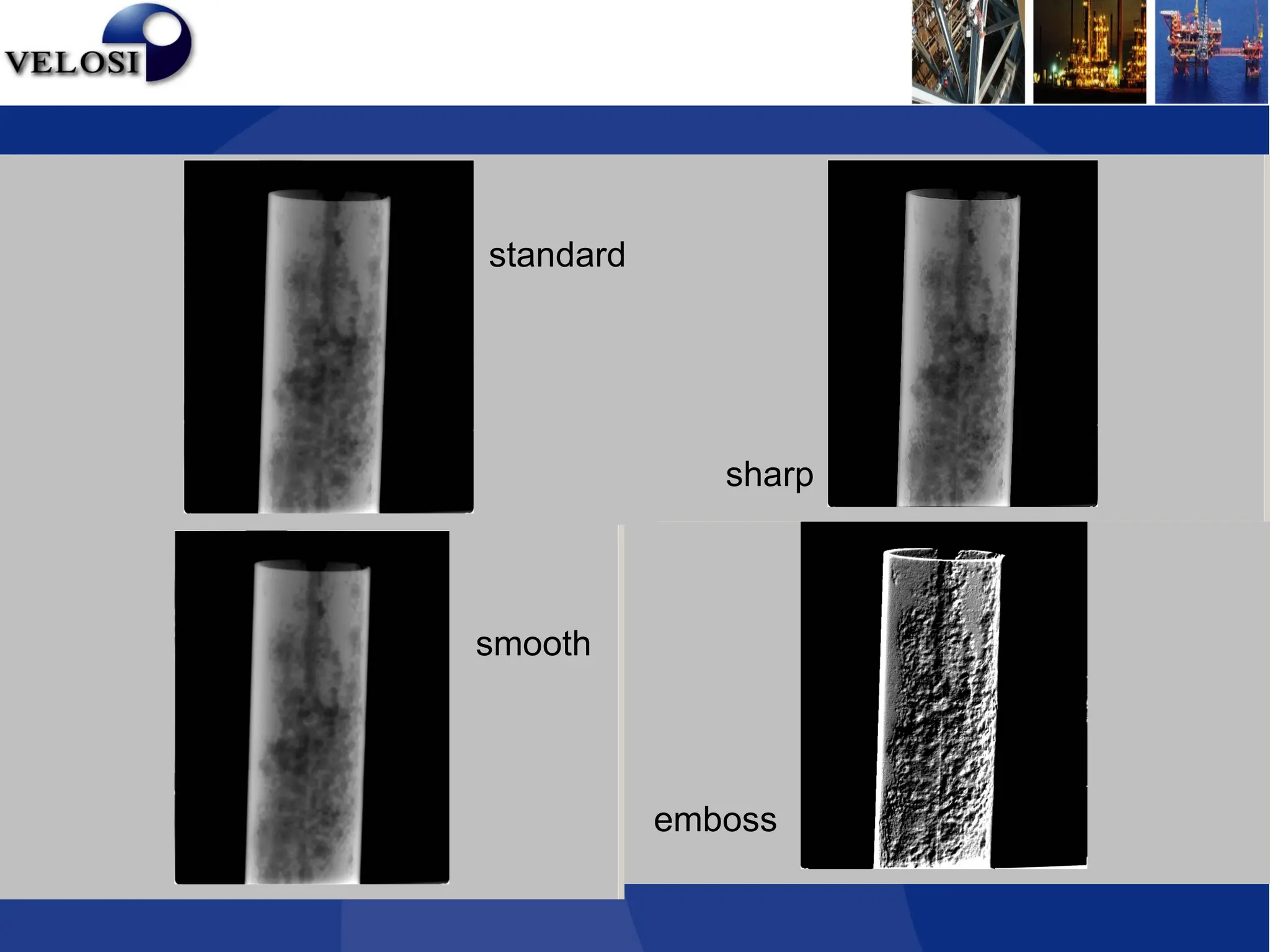
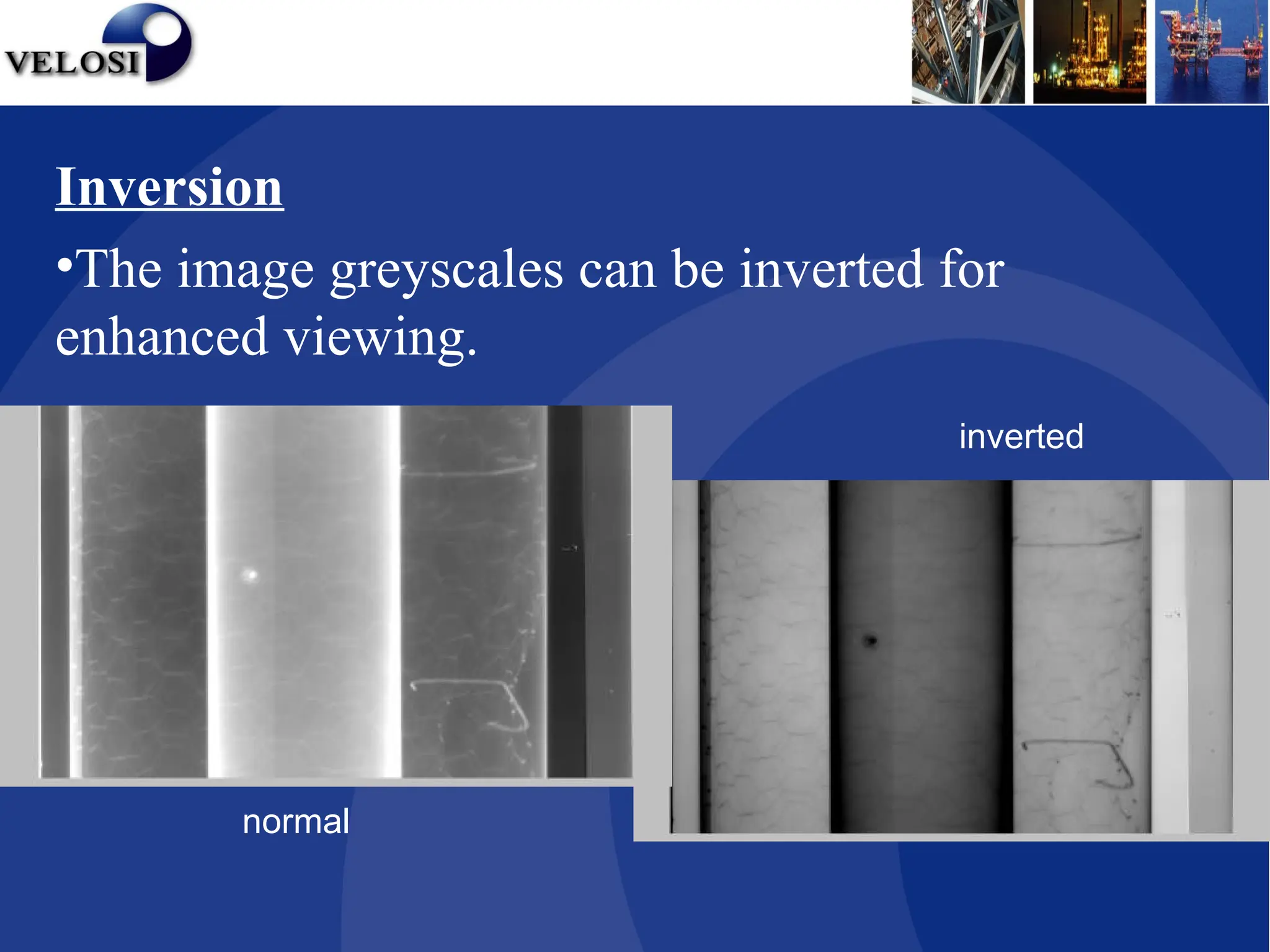
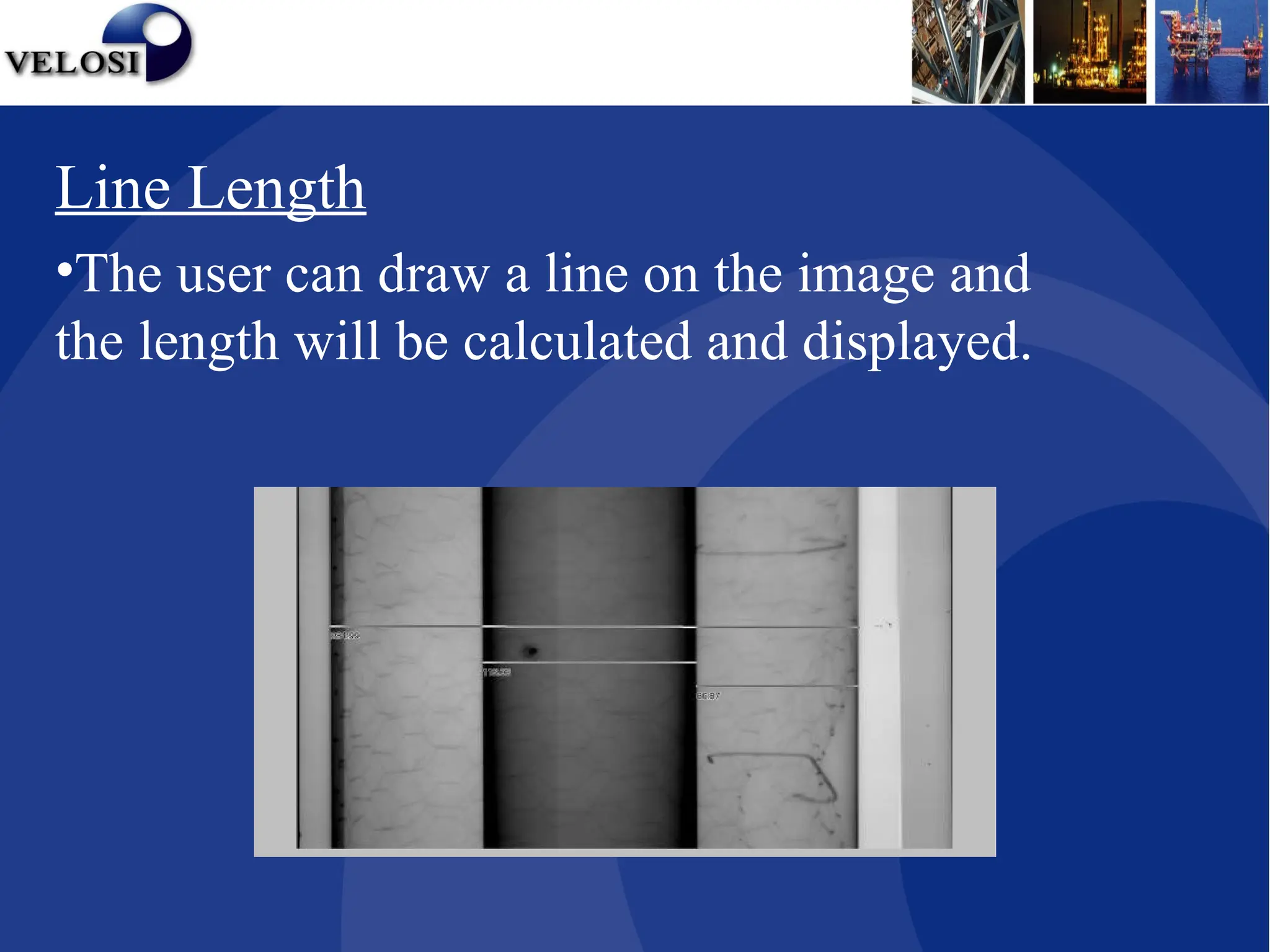
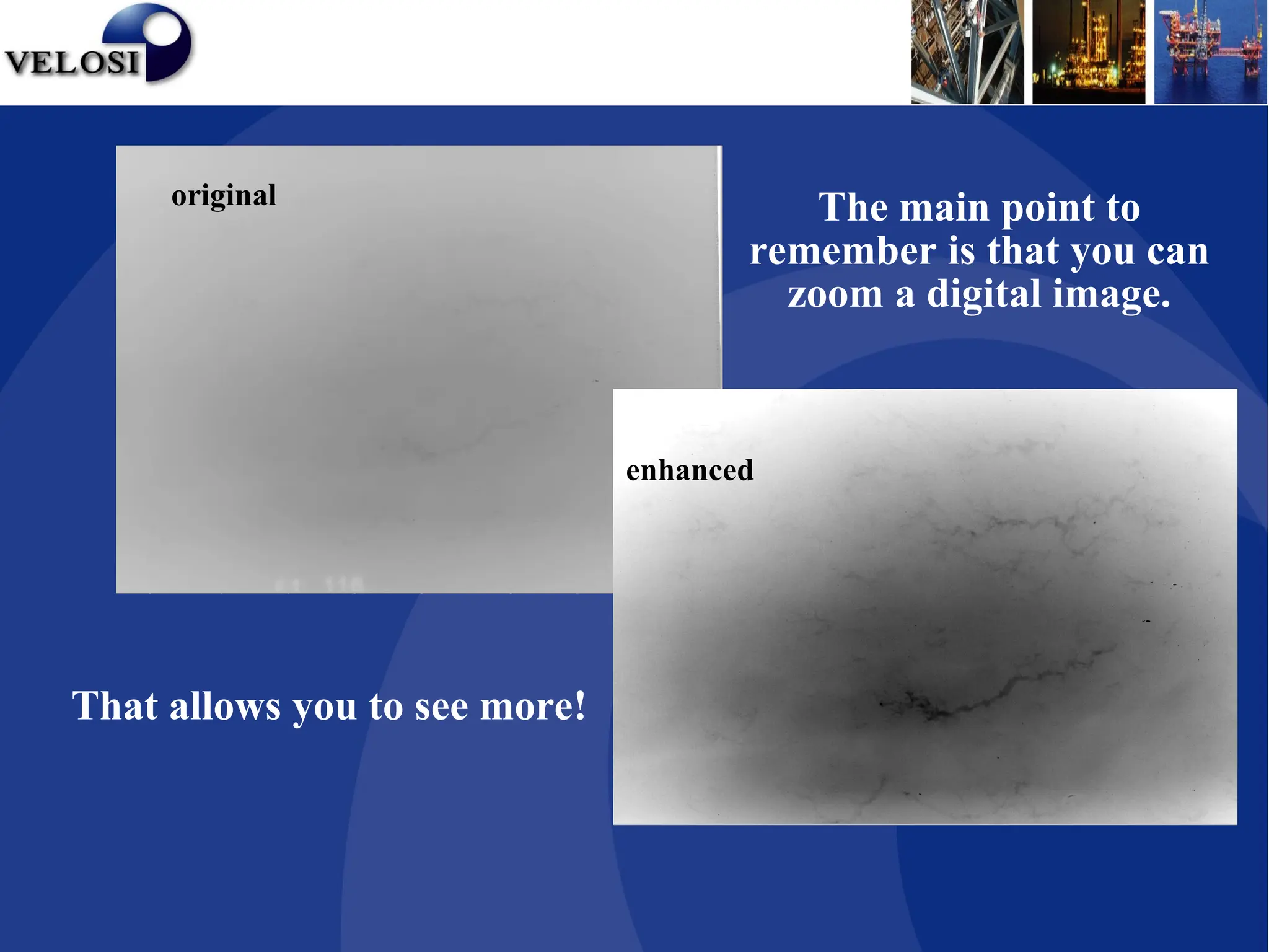
COMPUTED RADIOGRAPHY SYSTEM
What is Computed Radiography
It’s a Digital Radiographic Imaging process
with three major steps
I. Capture latent images on a special
imaging plates with the help of Gamma
rays / X rays
II. Digitize the latent image with help of a
laser scanner
III. Digital image enhancement for better
viewing
CR- Image Capture:
• Computed Radiography employs Imaging plates
(Phosphor pates) , which when irradiated, stores
a latent radiographic image for an unspecified
period of time.
• This is much the same fashion as classical X-Ray
film.
CR Image Capture
CR Cassette
PSP
CR Phosphor Screen Structure
X-rays/Gamma rays penetrating the specimen
stimulate the phosphors. The stimulated phosphors
remain in an excited state.
X-Rays
Phosphor Layer
Protective Layer
Substrate
Phosphor Grains
During exposure:
CR Image Extraction
Motor
A/D
Converter
Imaging
Plate
Optical
Scanner Photo-multiplier Tube
110010010010110
Laser Beam
As a laser scans the imaging plate, light (Photo stimulable
Luminescence) is emitted where X- rays stimulated the
phosphor during exposure.
The light is then converted to a digital value.
CR Image Extraction
CR Digital Image Enhancement
Digital images are typically sent to a computer
workstation where specialized software allows
manipulation and enhancement.
Enhancing Tools
• Window / level
• Zooming
• Kernels
• Rotation
• Inversion
CR Digital Image Enhancement
Measurement Tools
•Line Profile
•Line Length
•Point Profile
CR Digital Image Enhancement
Window / Levelling
• Window and leveling is designed to manage the mapping of
a large number of greyscale levels (GSL) acquired which in
turn permits the human eye to work within its narrow
grey scale sensitivity range.
• For example, digitized images can have up to 4096 GSLs
per pixel and with monitors displaying up to 256 (8 bits)
GSLs.
• The human eye can only perceive about 128 (7 bits) of GSL.
• Window corresponds to range of greyscale levels.
• Level represents mid point of the displayed range.
CR Digital Image Enhancement
1 bit - 2 levels of gray
Bit depth (gray levels)
2 bit – 4 levels of gray
4 bit - 16 levels of gray
6 bit - 64 levels of gray
Range of
Range of
Interest
Interest
4096 digital intensity values in the workstation
256
levels
on
display
256
levels
on
display
Window / Levelling
Benefits of window / levelling
• Wide dynamic latitude
• less retakes
• less film usage
• less time
• one exposure approach
Zoom
•When radiographic images are initially scanned
and displayed, they are viewed at 1:1 unless
predetermined to another size.
•The zoom or magnify factor can be changed
from 0.1x to 40x and can be applied as an R.O.I.
or overall application.
Benefits of Zoom
•Renders previously difficult to view data readily
detected.
Zoom 2.0x
Zoom 1.0x
Zoom 0.5x
Kernels
•Kernels allow for enhanced filtering of the image by
means of a convolution between kernel and the image.
•The filters have two functions, sharpening & smoothing,
and are used for attenuating unwanted frequencies in
digital signals.
•Sharpening performs a high-pass filter operation that
lessens the low spatial frequencies, e.g. sharpens edges
but may make image grainy.
•Smoothing performs a low-pass filter operation that
lessens the high spatial frequencies, e.g. blurs any image
graininess.
standard
emboss
smooth
sharp
Rotation / Mirror / Flip
•Images can be rotated in increments of 90º
(0, 90, 180 &270).
•Additionally they can be mirrored or flipped
therefore allowing viewing in any orientation
Inversion
•The image greyscales can be inverted for
enhanced viewing.
normal
inverted
Line Profile
•Allows the user to draw a line on the image and
a graph will be displayed plotting digital pixel
value vs. data point.
Point Profile
•The user can invoke the point profile form
which will display a 3 x 3 pixel matrix of digital
pixel values.
•Similar to traditional density measurement.
Line Length
•The user can draw a line on the image and
the length will be calculated and displayed.
Other Tools
•Region of Interest (ROI)
•Annotation – predefined or typed text
•Arrows & Lines
•Musica: Contrast Amplification
• Edge Contrast
• Latitude Reduction
• Noise Reduction
•Technique Sheets
Preserve the Original Data
•Rad View offers many image processing functions
to enhance the radiographic images. However, it is
important that a digital system archives all image
files in their original state to preserve the integrity of
the raw data.
•All enhancements or layer management never alter
the original image.
Rad View Software
Export Modes
•Images can easily be exported in many standard
graphic file formats. This way, remote users can
receive information and view inspection results
with any standard viewing software.
Rad View Software
Benefits of Computed RT
• Less retakes because of a wide dynamic latitude
• Dose reduction due to shorter exposures
• Reduced time in result processing
• Longevity, reusable up to 20,000 times
• Image Enhancement permits easier viewing
• High Image Sharpness
• Image Exportation
• Annotations
• Environment
General Questions?
• Does RadView require special exposure
parameters?
Yes, use approximately one tenth of a D7
exposure i.e.100kV 10mAm → 100kV 1mAm
• Can RadView imaging plates be used anywhere?
Yes, PSP or CR Phosphor plates can bend to suit
a 3” pipe.
• How does resolution compare with that of existing
film systems?
CR is comparable with Agfa D4 and D7 depending
on material and PSP plate used.
• However, this is dependant on the human eye and
monitor pixel size i.e. human eye has a best
resolution of approx 75µm, film resolution is approx
2µm and digital radiography is approx. 50µm.
original
enhanced
The main point to
remember is that you can
zoom a digital image.
That allows you to see more!
Limitations
• Shooting limitations of RT

CR Presentation.ppt - Computed Radiography

  • 1.
  • 2.
    What is ComputedRadiography It’s a Digital Radiographic Imaging process with three major steps I. Capture latent images on a special imaging plates with the help of Gamma rays / X rays II. Digitize the latent image with help of a laser scanner III. Digital image enhancement for better viewing
  • 3.
    CR- Image Capture: •Computed Radiography employs Imaging plates (Phosphor pates) , which when irradiated, stores a latent radiographic image for an unspecified period of time. • This is much the same fashion as classical X-Ray film.
  • 4.
  • 5.
  • 6.
    CR Phosphor ScreenStructure X-rays/Gamma rays penetrating the specimen stimulate the phosphors. The stimulated phosphors remain in an excited state. X-Rays Phosphor Layer Protective Layer Substrate Phosphor Grains During exposure:
  • 7.
  • 8.
    Motor A/D Converter Imaging Plate Optical Scanner Photo-multiplier Tube 110010010010110 LaserBeam As a laser scans the imaging plate, light (Photo stimulable Luminescence) is emitted where X- rays stimulated the phosphor during exposure. The light is then converted to a digital value. CR Image Extraction
  • 9.
    CR Digital ImageEnhancement Digital images are typically sent to a computer workstation where specialized software allows manipulation and enhancement.
  • 10.
    Enhancing Tools • Window/ level • Zooming • Kernels • Rotation • Inversion CR Digital Image Enhancement
  • 11.
    Measurement Tools •Line Profile •LineLength •Point Profile CR Digital Image Enhancement
  • 12.
    Window / Levelling •Window and leveling is designed to manage the mapping of a large number of greyscale levels (GSL) acquired which in turn permits the human eye to work within its narrow grey scale sensitivity range. • For example, digitized images can have up to 4096 GSLs per pixel and with monitors displaying up to 256 (8 bits) GSLs. • The human eye can only perceive about 128 (7 bits) of GSL. • Window corresponds to range of greyscale levels. • Level represents mid point of the displayed range. CR Digital Image Enhancement
  • 13.
    1 bit -2 levels of gray 1 bit - 2 levels of gray Bit depth (gray levels) Bit depth (gray levels)
  • 14.
    2 bit –4 levels of gray 2 bit – 4 levels of gray
  • 15.
    4 bit -16 levels of gray 4 bit - 16 levels of gray
  • 16.
    6 bit -64 levels of gray 6 bit - 64 levels of gray
  • 17.
    Range of Range of Interest Interest 4096digital intensity values in the workstation 4096 digital intensity values in the workstation 256 levels on display 256 levels on display
  • 18.
  • 19.
    Benefits of window/ levelling • Wide dynamic latitude • less retakes • less film usage • less time • one exposure approach
  • 20.
    Zoom •When radiographic imagesare initially scanned and displayed, they are viewed at 1:1 unless predetermined to another size. •The zoom or magnify factor can be changed from 0.1x to 40x and can be applied as an R.O.I. or overall application. Benefits of Zoom •Renders previously difficult to view data readily detected.
  • 21.
  • 22.
    Kernels •Kernels allow forenhanced filtering of the image by means of a convolution between kernel and the image. •The filters have two functions, sharpening & smoothing, and are used for attenuating unwanted frequencies in digital signals. •Sharpening performs a high-pass filter operation that lessens the low spatial frequencies, e.g. sharpens edges but may make image grainy. •Smoothing performs a low-pass filter operation that lessens the high spatial frequencies, e.g. blurs any image graininess.
  • 23.
  • 24.
    Rotation / Mirror/ Flip •Images can be rotated in increments of 90º (0, 90, 180 &270). •Additionally they can be mirrored or flipped therefore allowing viewing in any orientation
  • 25.
    Inversion •The image greyscalescan be inverted for enhanced viewing. normal inverted
  • 26.
    Line Profile •Allows theuser to draw a line on the image and a graph will be displayed plotting digital pixel value vs. data point. Point Profile •The user can invoke the point profile form which will display a 3 x 3 pixel matrix of digital pixel values. •Similar to traditional density measurement.
  • 27.
    Line Length •The usercan draw a line on the image and the length will be calculated and displayed.
  • 28.
    Other Tools •Region ofInterest (ROI) •Annotation – predefined or typed text •Arrows & Lines •Musica: Contrast Amplification • Edge Contrast • Latitude Reduction • Noise Reduction •Technique Sheets
  • 29.
    Preserve the OriginalData •Rad View offers many image processing functions to enhance the radiographic images. However, it is important that a digital system archives all image files in their original state to preserve the integrity of the raw data. •All enhancements or layer management never alter the original image. Rad View Software
  • 30.
    Export Modes •Images caneasily be exported in many standard graphic file formats. This way, remote users can receive information and view inspection results with any standard viewing software. Rad View Software
  • 31.
    Benefits of ComputedRT • Less retakes because of a wide dynamic latitude • Dose reduction due to shorter exposures • Reduced time in result processing • Longevity, reusable up to 20,000 times • Image Enhancement permits easier viewing • High Image Sharpness • Image Exportation • Annotations • Environment
  • 32.
    General Questions? • DoesRadView require special exposure parameters? Yes, use approximately one tenth of a D7 exposure i.e.100kV 10mAm → 100kV 1mAm • Can RadView imaging plates be used anywhere? Yes, PSP or CR Phosphor plates can bend to suit a 3” pipe.
  • 33.
    • How doesresolution compare with that of existing film systems? CR is comparable with Agfa D4 and D7 depending on material and PSP plate used. • However, this is dependant on the human eye and monitor pixel size i.e. human eye has a best resolution of approx 75µm, film resolution is approx 2µm and digital radiography is approx. 50µm.
  • 34.
    original enhanced The main pointto remember is that you can zoom a digital image. That allows you to see more!
  • 35.

Editor's Notes

  • #8 Within a CR reader, the IP is scanned with a laser beam in order to initiate the emission of light from the storage phosphors (photostimulated luminescence). The intensity of light emitted from the IP is proportional to the amount of radiation absorbed by the storage phosphor. The laser scans across the surface of the IP in a raster pattern. During the reading process, the light that is emitted from the IP is collected by a light guide & sent to a photomultiplier tube (PMT). The signal coming from the PMT is amplified, spatially sampled, & then sent to be converted to a digital signal (in an analog to digital converter). The resultant digital information can now be electronically transmitted, manipulated, & more efficiently stored.