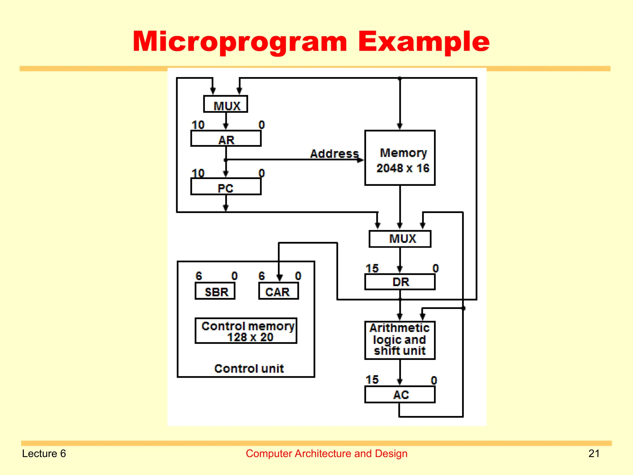
1
Computer Architecture and
Design
Computer Architecture and Design
Computer System
Engineering Department
2
Control Unit Design
Computer Architecture and Design
Lecture 6
Lecture 6 Computer Architecture and Design 3
Hardwired control unit
Instruction code
Combinational
Logic Circuits
Memory
Sequence Counter .
.
Control
signals
 Hardwired control units are generally
faster than micro programmed designs. In
hardwired control, all the control signals
required inside the CPU can be generated
using a state counter and a
programmable logic array (PLA ) circuit.
 A micro programmed control unit is a
relatively simple logic circuit that is
capable of
 (1) sequencing through microinstructions

Lecture 6 Computer Architecture and Design 4
Hardwired control unit
The Hardwired Control organization involves
the control logic to be implemented with
gates, flip-flops, decoders, and other digital
circuits.
Advantage: 1. Reduces the number of
components
2. Speed is fast
3. Produce the fast mode of operation.
Disadvantage :
Not flexible
Instruction set, the control logic is directly
implemented.
An occurrence of an error is more.
Complex decoding and sequencing logic.
Lecture 6 Computer Architecture and Design 5
Hardwired control unit
 Hardwired control unit generates the control
signals needed for the processor using logic
circuits
 Hardwired control unit is faster when
compared to microprogrammed control unit as
the required control signals are generated with
the help of hardware.
 Difficult to modify as the control signals that
need to be generated are hard wired.
 More expensive as everything has to be
realized in terms of logic gates.
 It cannot handle complex instructions as the
circuit design for it becomes complex.
Lecture 6 Computer Architecture and Design 6
Hardwired control unit
Lecture 6 Computer Architecture and Design 7
Hardwired control unit
 A Hard-wired Control consists of two decoders,
a sequence counter, and a number of logic
gates.
 An instruction fetched from the memory unit is
placed in the instruction register (IR).
 The component of an instruction register
includes:
 I bit, the operation code, and bits 0 through
11.
 The operation code in bits 12 through 14 are
coded with a 3 x 8 decoder.
 The outputs of the decoder are designated by
the symbols D0 through D7.
Lecture 6 Computer Architecture and Design 8
Microprogram control unit
 Micrprogrammed control unit generates the
control signals with the help of micro
instructions stored in control memory.
 This is slower than the hardwired control unit
because the microinstructions are to be
fetched from the control memory which is
time-consuming.
 Flexible
 Less expensive than hardwired control as
only micro instructions are used for
generating control signals.
 It can handle complex instructions.
 Control signals for many instructions can be
generated.
 occurrence of an error is less.
Lecture 6 Computer Architecture and Design 9
Microprogram control unit
Control
signals
Next Address
Generator
(sequencer)
CAR Control
Memory
CDR Decoding
Circuit
Memory
.
.
CAR: Control Address Register
CDR: Control Data Register
Instruction code
Fig: A
Fig: B
Lecture 6 Computer Architecture and Design 10
Microprogram control unit
 The Control memory address register specifies the
address of the micro-instruction.
 The Control memory is assumed to be a ROM,
within which all control information is
permanently stored.
 The control register holds the microinstruction
fetched from the memory.
 The micro-instruction contains a control word that
specifies one or more micro-operations for the
data processor.
 While the micro-operations are being executed,
the next address is computed in the next address
generator circuit and then transferred into the
control address register to read the next
microinstruction.
 The next address generator is often referred to as
Lecture 6 Computer Architecture and Design 11
Control Memory
 Control Memory is the storage in the microprogrammed control unit
to store the microprogram.
 Read-only memory (ROM)
 Content of word in ROM at given address specifies microinstruction
 Each computer instruction initiates series of microinstructions (micro
program) in control memory
 These microinstructions generate micro operations to
– Fetch instruction from main memory
– Evaluate effective address
– Execute operation specified by instruction
– Return control to fetch phase for next instruction
Control
memory
(ROM)
Control word
(microinstruction)
Address
Lecture 6 Computer Architecture and Design 12
 Control memory
– Contains microprograms (set of microinstructions)
– Microinstruction contains
• Bits initiate microoperations
• Bits determine address of next microinstruction
 Control address register (CAR)
– Specifies address of next microinstruction
Microprogrammed Control Organization
Control
word
Next Address
Generator
(sequencer)
CAR
Control
Memory
(ROM)
CDR
External
input
Lecture 6 Computer Architecture and Design 13
Microprogrammed Control Organization
 Next address generator (microprogram sequencer)
– Determines address sequence for control memory
 Microprogram sequencer functions
– Increment CAR
– Transfer external address into CAR
– Load initial address into CAR to start control operations
Lecture 6 Computer Architecture and Design 14
Microprogrammed Control Organization
• Control data register (CDR)- or pipeline register
– Holds microinstruction read from control memory
– Allows execution of microoperations specified by control
word simultaneously with generation of next
microinstruction
• Control unit can operate without CDR
Control
word
Next Address
Generator
(sequencer)
CAR
Control
Memory
(ROM)
External
input
Lecture 6 Computer Architecture and Design 15
Microprogram routines
 Routine
– Group of microinstructions stored in control memory.
 Each computer instruction has its own microprogram
routine to generate microoperations that execute the
instruction.
Lecture 6 Computer Architecture and Design 16
Microprogram Subroutines
 Subroutine
– Sequence of microinstructions used by other routines
to accomplish particular task
 Example
– Subroutine to generate effective address of operand
for memory reference instruction
 Subroutine register (SBR)
– Stores return address during subroutine call
Lecture 6 Computer Architecture and Design 17
Conditional Branching
 Branching from one routine to another depends on
status bit conditions
 Status bits provide parameter info such as
– Carry-out of adder
– Sign bit of number
– Mode bits of instruction
 Info in status bits can be tested and actions initiated
based on their conditions: 1 or 0
 Unconditional branch
– Fix value of status bit to 1
Lecture 6 Computer Architecture and Design 18
Mapping of Instruction
• Each computer instruction has its own
microprogram routine stored in a given
location of the control memory
• Mapping
– Transformation from instruction code bits to
address in control memory where routine is
located
Lecture 6 Computer Architecture and Design 19
Mapping of instructions
Lecture 6 Computer Architecture and Design 20
Address sequencing
Lecture 6 Computer Architecture and Design 21
Microprogram Example
Lecture 6 Computer Architecture and Design 22
Microprogram Example
Lecture 6 Computer Architecture and Design 23
Micro instruction fields
Lecture 6 Computer Architecture and Design 24
Micro instructions fields
Lecture 6 Computer Architecture and Design 25
Symbolic microinstruction
Lecture 6 Computer Architecture and Design 26
Symbolic Microprogram
Lecture 6 Computer Architecture and Design 27
Binary microprogram
Lecture 6 Computer Architecture and Design 28
Microprogram sequencer
Lecture 6 Computer Architecture and Design 29
ALLAH HAFIZ

Computer Architecture By Beenish lecture 6.ppt

  • 1.
    1 Computer Architecture and Design ComputerArchitecture and Design Computer System Engineering Department
  • 2.
    2 Control Unit Design ComputerArchitecture and Design Lecture 6
  • 3.
    Lecture 6 ComputerArchitecture and Design 3 Hardwired control unit Instruction code Combinational Logic Circuits Memory Sequence Counter . . Control signals  Hardwired control units are generally faster than micro programmed designs. In hardwired control, all the control signals required inside the CPU can be generated using a state counter and a programmable logic array (PLA ) circuit.  A micro programmed control unit is a relatively simple logic circuit that is capable of  (1) sequencing through microinstructions 
  • 4.
    Lecture 6 ComputerArchitecture and Design 4 Hardwired control unit The Hardwired Control organization involves the control logic to be implemented with gates, flip-flops, decoders, and other digital circuits. Advantage: 1. Reduces the number of components 2. Speed is fast 3. Produce the fast mode of operation. Disadvantage : Not flexible Instruction set, the control logic is directly implemented. An occurrence of an error is more. Complex decoding and sequencing logic.
  • 5.
    Lecture 6 ComputerArchitecture and Design 5 Hardwired control unit  Hardwired control unit generates the control signals needed for the processor using logic circuits  Hardwired control unit is faster when compared to microprogrammed control unit as the required control signals are generated with the help of hardware.  Difficult to modify as the control signals that need to be generated are hard wired.  More expensive as everything has to be realized in terms of logic gates.  It cannot handle complex instructions as the circuit design for it becomes complex.
  • 6.
    Lecture 6 ComputerArchitecture and Design 6 Hardwired control unit
  • 7.
    Lecture 6 ComputerArchitecture and Design 7 Hardwired control unit  A Hard-wired Control consists of two decoders, a sequence counter, and a number of logic gates.  An instruction fetched from the memory unit is placed in the instruction register (IR).  The component of an instruction register includes:  I bit, the operation code, and bits 0 through 11.  The operation code in bits 12 through 14 are coded with a 3 x 8 decoder.  The outputs of the decoder are designated by the symbols D0 through D7.
  • 8.
    Lecture 6 ComputerArchitecture and Design 8 Microprogram control unit  Micrprogrammed control unit generates the control signals with the help of micro instructions stored in control memory.  This is slower than the hardwired control unit because the microinstructions are to be fetched from the control memory which is time-consuming.  Flexible  Less expensive than hardwired control as only micro instructions are used for generating control signals.  It can handle complex instructions.  Control signals for many instructions can be generated.  occurrence of an error is less.
  • 9.
    Lecture 6 ComputerArchitecture and Design 9 Microprogram control unit Control signals Next Address Generator (sequencer) CAR Control Memory CDR Decoding Circuit Memory . . CAR: Control Address Register CDR: Control Data Register Instruction code Fig: A Fig: B
  • 10.
    Lecture 6 ComputerArchitecture and Design 10 Microprogram control unit  The Control memory address register specifies the address of the micro-instruction.  The Control memory is assumed to be a ROM, within which all control information is permanently stored.  The control register holds the microinstruction fetched from the memory.  The micro-instruction contains a control word that specifies one or more micro-operations for the data processor.  While the micro-operations are being executed, the next address is computed in the next address generator circuit and then transferred into the control address register to read the next microinstruction.  The next address generator is often referred to as
  • 11.
    Lecture 6 ComputerArchitecture and Design 11 Control Memory  Control Memory is the storage in the microprogrammed control unit to store the microprogram.  Read-only memory (ROM)  Content of word in ROM at given address specifies microinstruction  Each computer instruction initiates series of microinstructions (micro program) in control memory  These microinstructions generate micro operations to – Fetch instruction from main memory – Evaluate effective address – Execute operation specified by instruction – Return control to fetch phase for next instruction Control memory (ROM) Control word (microinstruction) Address
  • 12.
    Lecture 6 ComputerArchitecture and Design 12  Control memory – Contains microprograms (set of microinstructions) – Microinstruction contains • Bits initiate microoperations • Bits determine address of next microinstruction  Control address register (CAR) – Specifies address of next microinstruction Microprogrammed Control Organization Control word Next Address Generator (sequencer) CAR Control Memory (ROM) CDR External input
  • 13.
    Lecture 6 ComputerArchitecture and Design 13 Microprogrammed Control Organization  Next address generator (microprogram sequencer) – Determines address sequence for control memory  Microprogram sequencer functions – Increment CAR – Transfer external address into CAR – Load initial address into CAR to start control operations
  • 14.
    Lecture 6 ComputerArchitecture and Design 14 Microprogrammed Control Organization • Control data register (CDR)- or pipeline register – Holds microinstruction read from control memory – Allows execution of microoperations specified by control word simultaneously with generation of next microinstruction • Control unit can operate without CDR Control word Next Address Generator (sequencer) CAR Control Memory (ROM) External input
  • 15.
    Lecture 6 ComputerArchitecture and Design 15 Microprogram routines  Routine – Group of microinstructions stored in control memory.  Each computer instruction has its own microprogram routine to generate microoperations that execute the instruction.
  • 16.
    Lecture 6 ComputerArchitecture and Design 16 Microprogram Subroutines  Subroutine – Sequence of microinstructions used by other routines to accomplish particular task  Example – Subroutine to generate effective address of operand for memory reference instruction  Subroutine register (SBR) – Stores return address during subroutine call
  • 17.
    Lecture 6 ComputerArchitecture and Design 17 Conditional Branching  Branching from one routine to another depends on status bit conditions  Status bits provide parameter info such as – Carry-out of adder – Sign bit of number – Mode bits of instruction  Info in status bits can be tested and actions initiated based on their conditions: 1 or 0  Unconditional branch – Fix value of status bit to 1
  • 18.
    Lecture 6 ComputerArchitecture and Design 18 Mapping of Instruction • Each computer instruction has its own microprogram routine stored in a given location of the control memory • Mapping – Transformation from instruction code bits to address in control memory where routine is located
  • 19.
    Lecture 6 ComputerArchitecture and Design 19 Mapping of instructions
  • 20.
    Lecture 6 ComputerArchitecture and Design 20 Address sequencing
  • 21.
    Lecture 6 ComputerArchitecture and Design 21 Microprogram Example
  • 22.
    Lecture 6 ComputerArchitecture and Design 22 Microprogram Example
  • 23.
    Lecture 6 ComputerArchitecture and Design 23 Micro instruction fields
  • 24.
    Lecture 6 ComputerArchitecture and Design 24 Micro instructions fields
  • 25.
    Lecture 6 ComputerArchitecture and Design 25 Symbolic microinstruction
  • 26.
    Lecture 6 ComputerArchitecture and Design 26 Symbolic Microprogram
  • 27.
    Lecture 6 ComputerArchitecture and Design 27 Binary microprogram
  • 28.
    Lecture 6 ComputerArchitecture and Design 28 Microprogram sequencer
  • 29.
    Lecture 6 ComputerArchitecture and Design 29 ALLAH HAFIZ