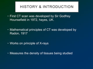
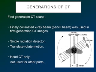
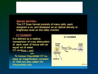
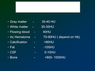
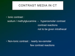
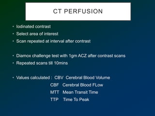
Computed Tomography
-Dr Prathmesh Mishra
Sr1 Neurosurgery
HISTORY & INTRODUCTION
• First CT scan was developed by Sir Godfrey
Hounsefield in 1972, hayes, UK.
• Mathematical principles of CT was developed by
Radon, 1917
• Works on principle of X-rays
• Measures the density of tissues being studied
• Transmitted radiation is measured by detectors located
in the Gantry.
• It is a movable frame that contains the x-ray tube
including collimators and filters, detectors, Data
Acquisition System (DAS), rotational components
including slip ring systems and all associated
electronics such as gantry angulation motors.
• Lasers or high intensity lights within or mounted on the
gantry which serves as an anatomical positioning guide
• View the CT scan as though you were looking up at it
from the patient’s feet.
• The density at a given point on an image represents
the
x-ray attenuation properties
within the patient along a line
between the x-ray focal spot
and the point on the
detector corresponding to
the point on the image.
GENERATIONS OF CT
First generation CT scans
• Finely collimated x-ray beam (pencil beam) was used in
first-generation CT images.
• Single radiation detector.
• Translate-rotate motion.
• Head CT only;
not used for other parts.
Second Generation
• Linear array of about
30 detectors, single x-ray tube,
rotate/translate motion,
• narrow angle (10 ° ) fan beam
3rd Generation
• A fan beam X-ray source is used several hundred
radiation detector
The curvilinear detector array provides constant distance
between source and each detector resulting in good
image
reconstruction.
360 degree rotate-rotate mention.
4TH generations
• Fourth generation was developed principally to
suppress ring artifacts. Several thousand individual
detectors.
• The mechanical motion is rotation of the x-ray source
around a fixed detector array (rotate stationary).
• As the fan beam passes across each detector, and
image projection is acquired.
• Imaging time is 1 s or less.
5th Generation
• A novel CT scanner has been developed
specifically for cardiac tomographic imaging.
• This “cine-CT” scanner does not use a
conventional x-ray tube.
• Cine-CT systems, also called electron beam
scanners, are marketed primarily to
cardiologists.
6th Generation
• In the early 1990s, the design of third- and fourth-
generation scanners evolved to incorporate slip ring
technology.
• A slip ring is a circular contact with sliding brushes that
allows the gantry to rotate continually, untethered by
wires.
• The use of slip-ring technology eliminated the inertial
limitations at the end of each slice acquisition, and the
rotating gantry was free to rotate continuously
7th Generation
• Multiple detector array computed tomographic (MDCT)
scanners use several, closely spaced, complete
detector arrays. With no table translation (nonhelical
acquisition), each detector array acquires a separate
axial CT image.
• Single detector – less spatial resolution
• MDCT – slice thickness depend on detector size
TYPES OF CT
Sequential CT :
• Single slice with single rotation of tube
• Time consuming & suboptimal resolution
Helical / Spiral CT
• Speed
• Reconstruction
POST-IMAGE PROCESSING
• Multiplanar reformating :
For patients who cannot be positioned properly
• 3D CT :
For spatial information / surface characteristics
facial # / anomalies
• CT Angiography :
for vascular injuries
100-120 ml contrast required
CT NUMBER / HOUNSEFIELD
UNIT
CT TERMINOLOGIES
• Gray matter - 35-40 HU
• White matter - 30-35HU
• Flowing blood - 40HU
• Ac Hematoma - 70-90HU ( depend on Hb)
• Calcification - >80HU
• Fat - -100HU
• CSF - 0-10HU
• Bone - +800- 1000HU
CONTRAST MEDIA IN CT
• Ionic contrast :
sodium / methylglucamine - hyperosmolar contrast
contrast reactions
not to be given intrathecal
• Non-Ionic contrast : nearly iso-osmolar
few contrast reactions
CT PERFUSION
• Iodinated contrast
• Select area of interest
• Scan repeated at interval after contrast
• Diamox challenge test with 1gm ACZ after contrast scans
• Repeated scans till 10mins
• Values calculated : CBV Cerebral Blood Volume
CBF Cerebral Blood FLow
MTT Mean Transit Time
TTP Time To Peak
• Ischemic Stroke : increased MTT & decreased CBF
• Stenosis : Decreased CBV CBF Increased MTT &
TTP
• Steal : Stenosis pattern after ACZ challenge
• PWI has more artifact than CTP
Computed Tomography.pptx

Computed Tomography.pptx

  • 1.
    Computed Tomography -Dr PrathmeshMishra Sr1 Neurosurgery
  • 2.
    HISTORY & INTRODUCTION •First CT scan was developed by Sir Godfrey Hounsefield in 1972, hayes, UK. • Mathematical principles of CT was developed by Radon, 1917 • Works on principle of X-rays • Measures the density of tissues being studied
  • 3.
    • Transmitted radiationis measured by detectors located in the Gantry. • It is a movable frame that contains the x-ray tube including collimators and filters, detectors, Data Acquisition System (DAS), rotational components including slip ring systems and all associated electronics such as gantry angulation motors. • Lasers or high intensity lights within or mounted on the gantry which serves as an anatomical positioning guide
  • 4.
    • View theCT scan as though you were looking up at it from the patient’s feet. • The density at a given point on an image represents the x-ray attenuation properties within the patient along a line between the x-ray focal spot and the point on the detector corresponding to the point on the image.
  • 5.
    GENERATIONS OF CT Firstgeneration CT scans • Finely collimated x-ray beam (pencil beam) was used in first-generation CT images. • Single radiation detector. • Translate-rotate motion. • Head CT only; not used for other parts.
  • 6.
    Second Generation • Lineararray of about 30 detectors, single x-ray tube, rotate/translate motion, • narrow angle (10 ° ) fan beam
  • 7.
    3rd Generation • Afan beam X-ray source is used several hundred radiation detector The curvilinear detector array provides constant distance between source and each detector resulting in good image reconstruction. 360 degree rotate-rotate mention.
  • 8.
    4TH generations • Fourthgeneration was developed principally to suppress ring artifacts. Several thousand individual detectors. • The mechanical motion is rotation of the x-ray source around a fixed detector array (rotate stationary). • As the fan beam passes across each detector, and image projection is acquired. • Imaging time is 1 s or less.
  • 9.
    5th Generation • Anovel CT scanner has been developed specifically for cardiac tomographic imaging. • This “cine-CT” scanner does not use a conventional x-ray tube. • Cine-CT systems, also called electron beam scanners, are marketed primarily to cardiologists.
  • 10.
    6th Generation • Inthe early 1990s, the design of third- and fourth- generation scanners evolved to incorporate slip ring technology. • A slip ring is a circular contact with sliding brushes that allows the gantry to rotate continually, untethered by wires. • The use of slip-ring technology eliminated the inertial limitations at the end of each slice acquisition, and the rotating gantry was free to rotate continuously
  • 11.
    7th Generation • Multipledetector array computed tomographic (MDCT) scanners use several, closely spaced, complete detector arrays. With no table translation (nonhelical acquisition), each detector array acquires a separate axial CT image. • Single detector – less spatial resolution • MDCT – slice thickness depend on detector size
  • 12.
    TYPES OF CT SequentialCT : • Single slice with single rotation of tube • Time consuming & suboptimal resolution Helical / Spiral CT • Speed • Reconstruction
  • 13.
    POST-IMAGE PROCESSING • Multiplanarreformating : For patients who cannot be positioned properly • 3D CT : For spatial information / surface characteristics facial # / anomalies • CT Angiography : for vascular injuries 100-120 ml contrast required
  • 14.
    CT NUMBER /HOUNSEFIELD UNIT
  • 15.
  • 18.
    • Gray matter- 35-40 HU • White matter - 30-35HU • Flowing blood - 40HU • Ac Hematoma - 70-90HU ( depend on Hb) • Calcification - >80HU • Fat - -100HU • CSF - 0-10HU • Bone - +800- 1000HU
  • 19.
    CONTRAST MEDIA INCT • Ionic contrast : sodium / methylglucamine - hyperosmolar contrast contrast reactions not to be given intrathecal • Non-Ionic contrast : nearly iso-osmolar few contrast reactions
  • 20.
    CT PERFUSION • Iodinatedcontrast • Select area of interest • Scan repeated at interval after contrast • Diamox challenge test with 1gm ACZ after contrast scans • Repeated scans till 10mins • Values calculated : CBV Cerebral Blood Volume CBF Cerebral Blood FLow MTT Mean Transit Time TTP Time To Peak
  • 21.
    • Ischemic Stroke: increased MTT & decreased CBF • Stenosis : Decreased CBV CBF Increased MTT & TTP • Steal : Stenosis pattern after ACZ challenge • PWI has more artifact than CTP