SlideShare a Scribd company logo
1 of 23
Download to read offline
SERVICE MANUAL
RATED CAPACITY : 2000~3000kg
SF20-30D/L/G
CMP20-30D/L/G
#40–1, Ungnam-Dong,
Changwon-City,Kyungnam,
Korea
Part No. 8034924
Manual No. SM688
Manufactured by
Rev.2
Mar,2004
1
FOREWORD
This shop manual has been prepared as an aid to improve quality of repairs by giving the
serviceman an accurate understanding of the product and by illustrating the correct way to
perform repairs and make judgements. Make sure you understand the contents of this manual
and use it to the full effect at every opportunity.
This shop manual mainly contains the technical information necessary for operations performed
in a service workshop.
For ease of understanding, the manual is divided into sections for each main system of the
machine, and the sections are further divided into groups.
HOW TO READ THIS MANUAL
CHAPTER AND SECTION
This manual is issued as a guide to carrying out repair and maintenance. To easily understand
this manual it is divided as follows :
Example) 10 – 01
Section number (01 : Structure and function)
Chapter number (10 : Engine)
FOREWORD
G E N E R A L
00
02
• Improper operation and maintenance of this machine could result in serious injury or death.
• Read the Operation and Maintenance Manual carefully BEFORE operating the machine.
• Always keep the Operation and Maintenance Manual and Parts catalogue near the work
area.
• Obey precautions concerning flammable liquids, hazardous fluids, oils, lubricants and
cleaning solvents.
• To prevent injury to workers, this symbol is used to mark safety precautions in this
manual. The precautions accompanying this symbol should always be followed carefully.
• The specifications contained in this shop manual are subject to change at any time and
without any advance notice. Contact your SAMSUNG distributor for the latest information.
!
SAFETY!
2
PAGE
Page numbering is started from each section. Therefore, revised pages can be easily inserted.
Also, additional pages and revision number can be indicated.
Ex) 15 – 1 ③
3rd revision
Additional page from page 15
15th page of the section
For the revision status in this manual, refer to REVISION HISTORY.
SYMBOLS
The following symbols as defined below are used in this manual to convey the intent of the
instructions concerning safety and repair.
FOREWORD
G E N E R A L
00
02
Symbol Item Remarks
Safety
Caution
Tightening
torque
Tool
Adhesive
Lubricating
Special safety precautions are necessary when
performing the work.
Special technical precautions or other precautions for
preserving standards are necessary when performing
the work.
Places that require special attention for the tightening
torque during assembly.
Places that require proper tools used in assembling
and disassembling.
Places to be applied with adhesive.
Places where oil or lubricant must be added.
!
1
SAFETY
G E N E R A L
00
03
GENERAL PRECAUTIONS
SAFETY PRECAUTIONS
• When carrying out any operation or maintenance, have trained and experienced personnel carry
out the work.
• When carrying out any operation or maintenance, carefully read the Operation and Maintenance
Manual.
Read all the precautions given on the decals which are fixed to the machine.
SAFETY DEVICE
• Make sure that all guards and covers are mounted in their proper position. Repair or replace
if damaged.
• Pay attention to the method of using any safety locking device or safety belt.
SAFETY CLOTHES AND HELMET
• Wear the specified work clothes in the correct manner.
• Use the specified protective gear (helmet, safety glasses, safety shoes, mask, gloves).
Guard against injury from flying pieces of metal
or debris, wear goggles, gloves and helmet.
Always have a trained and experienced welder
carry out any welding work.
When carrying out welding work, always wear
welding gloves, apron, glasses, cap and other
clothes suitable for welding work.
EX048
W A R N I N G!
SERIOUS OR FATAL INJURY MAY RESULT TO YOURSELF OR OTHERS IF NOT FOLLOWED
This fork lift should not be operated by anyone who is not authorized and properly trained.
Read the Operators Manual carefully, and make yourself familiar with your fork lift.
Inspect and check your fork lift daily before and after use. Do not operate a faulty or damaged fork lift.
Repair work should be done by authorized and trained persons only.
To protect from falling objects, make sure that the Overhead Guard and Load Backrest are correctly mounted and in good condition.
Before starting engine, always set forward/reverse lever in neutral, with hand brake on.
Drive carefully, keeping forks and attachments as low as possible & fully tilted back.
Keep a careful lookout for people, obstructions and the path of travel. Watch clearance, especially overhead and tail swing.
Do not stick hands, feet and other parts of your body outside the Operatorls compartment.
Drive forward when you are climbing a slope with a load. Drive in reverse when you are descending with loads. Do not turn while on a slope.
Slow down before turning. Avoid any sudden start, stop or turning. Lateral tipover can occur if the fork lift is improperly operated.
Do not load fork lift over capacity limit designated on the load chart. Do not lift unstable loads.
This fork lift is not designed for raising or transporting people. Do not use fork lift for those purposes under any circumstances.
Before you get off fork lift, make sure the hand brake is set, lower forks or attachments, put forward/reverse lever in neutral position and
turn off key switch. Do not park on a slope. P/NO.6092-13130
2
SAFETY
G E N E R A L
00
03
PREPARE FOR EMERGENCIES
• Know where fire extinguishers are located and
how to use them.
• Keep a first aid kit and an eye wash kit near
the work area.
• Keep emergency numbers for doctors, ambul-
ance service, hospital, and fire department near
your telephone.
HANDLE FLUIDS SAFELY–AVOID FIRES
• Handle fuel with care it is highly flammable.
• Do not refuel the machine while smoking or
when near open flame or sparks.
Always stop the engine before refueling
machine. Fill the fuel tank outdoors.
• Store flammable fluids away from fire hazards.
Do not incinerate or puncture pressurized
containers.
DISPOSE OF FLUIDS PROPERLY
• Improperly disposing of fluids can harm the
environment and ecology. Before draining any
fluids, find out the proper way to dispose of
waste from your local environmental agency.
• Catch draining fuel, oil, or other fluids in
suitable containers. Do not use food or
beverage containers that may mislead someone
into drinking from them. Wipe up spills at once.
• Do not pour oil into the ground, down a drain,
or into a stream, pond, or lake. Observe
relevant environmental protection regulations
when disposing of oil, fuel, coolant, brake fluid,
filters, batteries, and other harmful waste.
EX036
EX028
EX043
3
SAFETY
G E N E R A L
00
03
AVOID HARMFUL ASBESTOS DUST
• Avoid breathing dust that may be generated
when handling components containing asbestos
fibers. Inhaled asbestos fibers may cause lung
cancer.
EX025
4
SAFETY
G E N E R A L
00
03
PREPARATIONS FOR WORK
WARN OTHERS OF SERVICE WORK
• Unexpected machine movement can cause
serious injury.
• Before performing any work on the machine,
attach a “Do Not Operate” tag to the steering
wheel or the right control lever.
• When carrying out any operation with two or
more workers, always agree on the operating
procedure before starting.
USE TOOLS PROPERLY
• Use a tool only for its designed application.
• Keep all tools in good condition and know the
correct way to use them.
• Decide on a place in the repair workshop to
keep tools and removed parts.
• Always keep the work area clean and make
sure that there is no dirt or oil on the floor.
• Before adding oil or making any repairs, park
the machine on hard, level ground and put
blocks under the wheels or tracks to prevent
the mahcine from moving.
• Before starting work, lower the forks or any
other work equipment to the ground.
• Turn the engine OFF, remove the start key,
and apply the parking brake.
• Illuminate your work area adequately but safely.
Use a portable safety light for working inside
or under the machine. Make sure the bulb is
enclosed by a wire cage. The hot filament of
an accidentally broken bulb can ignite spilled
fuel or oil.
EX033
EX042
5
SAFETY
G E N E R A L
00
03
USE HANDHOLDS AND STEPS
• Do not jump onto or down from the fork lift.
• When getting on or off the fork lift, use the
step provided.
• Do not grasp an operating lever or steering
wheel when getting on or off.
• Always keep the step clean and repair it if
damaged.
• Never operate with wet or oily hands and feet.
OPERATE FROM THE OPERATOR’S SEAT
• Do not operate the fork lift from any place
other than the designated operator’s position.
• Improper seating may cause serious injury.
FX019
FX020
FX019
FX020
1
CONSTRUCTION
Power flow is from torque converter turbine, to turbine (clutch) shaft and gears, then through
either forward gear or reverse idler shaft, to the output gear mounted on final drive pinion shaft.
Transmission and differential are housed in a one–piece transmission case.
Torque converter housing joined to transmission case through an adaptor (or spacer) plate holds
the converter stator support and reverse idler outer bearing.
Pump drive is from converter impeller hub gear, through an idler gear to the pump gear mounted
on charging pump shaft.
Final drive pinion gear shaft, mounted in tapered roller bearings at both ends in transmission
case, is adjusted for mounting distance, and ring and pinion gear contact by, shim a pack
installed behind the pinion gear inner tapered roller bearing cup in the transmisson case. Pinion
shaft bearing preload is adjusted with shims behind outer bearing cone on the pinion shaft.
STRUCTURE AND MAINTENANCE
T R A N S A X L E
20
01
TA18 Transaxle assembly includes:
• Torque converter
• Single–speed forward and reverse powershift transmission with integral differential and
drive axle
• Full–floating straight drive axle
• Automotive–type drum and shoe brakes
• Gear–driven pump drive
• Electric shift control, hydraulic inching control
2
Final drive ring gear is bolted to differential carrier. Differential support is by opposed tapered
roller bearings mounted on inner end of wheel end housings, which are bolted to openings in
transmission case at the sides of the differential. Differential bearing preload and ring gear
clearance (backlash) is maintained by shims placed behind differential bearing cones on wheel
end housings. Adjustment of differential bearing preload or ring gear backlash requires trial
assembly, checking, and disassembly of wheel end housings until correct adjustment is obtained.
Drive axle wheel hubs/brake drums are supported by double tapered roller bearings on outer
end of wheel end housings. Drive axle shaft flange bolted to wheel hubs are full–floating in
differential. Service brake backing plates are bolted to mounting flanges on wheel end housings.
Wheel bearings are lubricated from the transaxle sump.
Control valve is mounted on pad at top of transmission case. Oil from charging pump flows via
filter and pressure regulator to control valve through an external oil supply line. Oil from control
valve is delivered to clutches through passages in housing and oil distributor sleeve and seal
rings at forward–clutch end of turbine/clutch shaft. Excess pump oil volume and converter–out
oil, flows to oil cooler and returns to transmission housing at base of control valve, then through
center of turbine/clutch shaft back to converter.
HYDRAULIC CIRCUIT
STRUCTURE AND MAINTENANCE
T R A N S A X L E
20
01
3
SERVICE MAINTENANCE
SERVICE
The transaxle has two service openings:
1. Dipstick / oil fill tube in central side axle
housing.
2. Drain plug, in bottom of transmission case.
FLUID LEVEL CHECK
Check the transaxle fluid level with:
• Fork lift on a level surface
• Engine idling with transmission in NEUTRAL
• Oil at operating temperature 82~93°C (180~200°F)
① Remove the transaxle oil level plug the front of central housing of driving wheel.
② The oil level is correct when the oil reaches the full mark on dipstick.
③ Add recommended fluid only, as required.
FLUID AND FILTER CHANGE
It is recommended to:
• Drain and replace the transaxle fluid every
1000 operating hours.
• The oil should be drained when warmed to
operating temperature, 82~93°C (180~200°F)
• Replace the transaxle oil filter every 500
operating hours. See NOTICE below.
IMPORTANT
When the transaxle is new or rebuilt, it is recommended to change the oil filter after
the first 50 hours and again after 100 operating hours.
① Remove drain plug from bottom of transmission case. Drain old oil into suitable drain pan.
② Remove old oil filter. The oil filter is mounted near the top of converter housing above
transmission.
!
STRUCTURE AND MAINTENANCE
T R A N S A X L E
20
01
4
Take special care when removing the filter to avoid oil remaining in filter from draining
onto floor. Loosen the filter using a filter wrench. Remove filter while holding a pad
of cloth or other absorbent material under the open end to absorb any excess oil that
may drain out of filter.
③ Install a new oil filter. Follow the installation instructions printed on filter.
Always use genuine SAMSUNG parts
REFILLING THE TRANSAXLE
After drive axle and transmission housing has drained completely,
• Install drain plug.
• Loosen the oil level plug and fill the oil upto the plug hole.
• Start the engine and run at idle speed (700~800 rpm) in NEUTRAL for 2~3 minutes to prime
the converter and cooler lines.
• Recheck oil level with engine running at idle speed. [82~93°C (180~200°F)]
• Check for leaks at drain plug and oil filter.
SPECIFICATION
PRESSURE SPECIFICATION
• Regulator valve pressure : 1108~1451kPa (160~210 psi) @ 1800 rpm
Check Point : Oil supply line at converter
• Converter In/Lube Pressure : 176~314kPa (26~45 psi ) @ 1800 rpm
Check Point : Return from cooler
• Converter Safety Valve Pressure : 729~827kPa (105~120 psi) @
(Trans in NEUTRAL) 1800 rpm (Refefence only)
Check Point : None with line to cooler blocked
• Clutch Pressure : 1034kPa (150 psi) @
(Forward, Reverse applied) 700~800 rpm idle
Check Point : At control valve Normally 103kpa (15 psi) less than regulator
(1/8 NPTF) pressure 1000kpa (145 psi min)
• Clutch Pressure : Regulator pressure
(in NEUTRAL)
!
!
STRUCTURE AND MAINTENANCE
T R A N S A X L E
20
01
5
NOTES
• All rpm’s noted are engine speed.
• All clutch pressures are at engine idle speed with clutch engaged, unless otherwise
noted.
• Oil at operating temperature 82~93°C (180~200°F)
• Refer to following illustrations for check point locations.
PRESSURE CHECK POINTS
!
STRUCTURE AND MAINTENANCE
T R A N S A X L E
20
01
6
STRUCTURE AND MAINTENANCE
T R A N S A X L E
20
01
SERVICE BRAKE ADJUSTMENT
PREPARATION
1. The service brakes on the transaxle may be adjusted from the inner side through the backing
plate (all models), or from the outer side through access openings in the wheel
hub/brake drum (later models).
2. Brake clearance is measured between brake shoe and drum, with brakes fully released.
Brake clearance : 0.255~0.304 mm (.010~.012 in)
CAUTION : Be sure transmission directional control is in NEUTRAL and fork lift
prevented from moving when parking brake is released.
3. Release parking brake.
IMPORTANT – Do not overtighten brakes.
It is very difficult to release the ratchet wheel pawl and back off adjustment of the
brake.
!
!
STRUCTURE AND MAINTENANCE
T R A N S A X L E
7
20
01
ADJUSTMENT AT BACKING PLATE
1. Remove the 4 dust plugs in brake backing plate.
2. Use a feeler (thickness) gauge to check the clearance between each shoe and drum. Use a
brake adjuster tool to rotate the adjuster ratchet wheel in the brake.
3. Use a screwdriver to push on and release the ratchet pawl when it is necessary to back off
adjustment (increase clearance) of the brake.
4. Carefully adjust clearance between brake shoes and drum to 0.255~0.304 mm (.010~.012 in)
measured at dust plug openings at outer sides of backing plate.
5. Replace the dust plugs in brake backing plate when adjustment is completed.
ADJUSTMENT AT WHEEL HUB
Openings in the wheel hub/brake drum have been provided for easier access to check and
adjust the service brakes from the outer side. Requires removal of drive wheel and tire assembly.
Some models may have only a slot for measuring brake clearance ; adjustment is made through
the plug openings on backing plate. Later models have a slot and circular opening for access
also to the adjuster. The opening is enclosed with a dust cover held in place by a single screw.
1. Remove wheel and tire assembly from wheel hub.
WARNING–Pneumatic Tire Wheels
Before loosening wheel mounting bolts or nuts, release the air pressure from the tire.
Failure to release the air pressure from the tire can result in serious injury or death.
2. Remove dust cover from access opening in wheel hub/brake drum.
3. Use feeler (thickness) gauge to check the clearance between each shoe and drum. Use a
brake adjuster tool to rotate the adjuster ratchet wheel in the brake.
4. Use a tool with a hook to pull on and release the ratchet pawl when it is necessary to back
off adjustment (increase clearance) of the brake.
!
8
IMPORTANT – Do not overtighten brakes.
It is very difficult to release the ratchet wheel pawl and back off adjustment of the
bake.
5. Carefully adjust clearance between brake shoes and drum to 0.255~0.304 mm (.010~.012 in)
measured at slot opening. Move slot by rotating brake drum to check clearance at the
illustrated position for each brake shoe. (20–01–6)
6. After adjusting brakes, install dust cover over access opening in the wheel hub.
7. Install wheel and tire assembly on the drive axle wheel hub.
8. Install wheel mounting lug nuts and tighten to spec : 637~718 Nm (471~531 lbf·ft)
!
STRUCTURE AND MAINTENANCE
T R A N S A X L E
20
01
1
SERVICE BRAKE ADJUSTMENT
T R A N S A X L E
20
02
PRECAUTION
• Before attempting any repairs or overhaul of this assembly, please read through the entire
disassembly and assembly procedures first.
Cleanliness is of extreme importance in the repair and overhaul of this assembly.
• The exterior surface of the unit MUST be thoroughly cleaned of all dirt and foreign substances
to prevent contamination of the parts during disassembly and overhaul. Perform all disassembly
and assembly work in a clean area. Protect all components from dust and dirt while repairs
are being made.
• Keep all parts in order as disassembly progresses. Take care to properly identify each part
and its order of removal. If necessary, keep notes and put marking on parts using a
nondestructive marker such as a felt–tipped pen.
REMOVE AUXILIARY SUBASSEMBLIES
1. Remove torque converter assembly by carefully sliding it off the turbine (clutch) shaft and
stator support.
2. Disassemble converter drive plate and adaptor, as needed.
Remove the :
3. Oil filter
4. Charging pump
5. Oil supply line assembly
6. Transmission control valve assembly
!
2
SERVICE BRAKE ADJUSTMENT
T R A N S A X L E
20
02
WHEEL END
1. Loosen and remove the axle shaft fasteners.
2. Remove axle shaft.
3. Unbend (straighten) the lockplate tabs from the bolt heads of the wheel bearing retainer plate
fasteners.
4. Remove the bearing retainer plate fasteners.
5. Remove the lockplate, bearing retainer plate and wheel bearing shims.
6. Pull wheel hub out to loosen bearing (you may have to tap on hub or pry at brake backing
plate), remove outer wheel bearing, then remove the wheel hub/brake drum assembly with
inner wheel bearing and oil seal.
8
7
4
6 5 3
2 1
3
SERVICE BRAKE ADJUSTMENT
T R A N S A X L E
20
02
IMPORTANT
This oil seal is a type that seals internally, and is lined with sealing compound on
the inner diameter that sticks and seals to the spindle.
Removing the wheel hub from the spindle breaks that seal. Replace with new seal
each time that the wheel hub is removed from wheel end housing.
7. Before removal of wheel end housing, mark the housing and the transmission case for
same–location matching at reassembly. Loosen and remove the housing bolts and washers.
8. Remove wheel end housing from transmission case.
9. If the differential bearing on the inner end of the wheel end housing is to be removed and
replaced, use a bearing puller, if necessary. Wire bearing shims to wheel end housing for
storage until reassembly.
10. Repeat procedures of Steps 1 through 9 for opposite wheel end disassembly.
11. Remove the differential assembly from transmission case.
!
Thank you very much for
your reading. Please Click
Here. Then Get COMPLETE
MANUAL. NO WAITING
NOTE:
If there is no response to
click on the link above,
please download the PDF
document first and then
click on it.
4
SERVICE BRAKE ADJUSTMENT
T R A N S A X L E
20
02
BRAKE ASSEMBLY REMOVAL
Brake removal is optional for brake overhaul as necessary.
1. Remove the upper brake shoe return springs.
2. Remove lower return spring.
3. Remove brake shoe hold–down (guide)
springs.
4. Disconnect parking brake cable.
Remove the brake shoes.
5. Remove brake backing plate fasteners and
washers.
6. Remove backing plate and parking brake
cable assembly from wheel end housing.
7. Remove drive axle support and spacer from
wheel end housing.
5
SERVICE BRAKE ADJUSTMENT
T R A N S A X L E
20
02
SEPARATION OF CONVERTER HOUSING AND
ADAPTOR PLATE
1. Remove the fasteners and washers which mount the converter housing to transmission case
through the adaptor plate.
2. From other side, remove the bolts and washers which mount adaptor (spacer) plate to
converter housing.
3. Remove the clutch pressure–regulating valve assembly (also oil filter mounting base).
IMPORTANT
Pry only at the dowel pins to remove adaptor plate. Dowel pins must be removed
before reassembly. See later instructions.
4. Separate converter housing from adaptor plate.
5. Remove impeller hub gear from stator support.
6. Remove pump drive idler gear and bearing, outer and inner thrust washers, and idler shaft.
7. Remove adaptor plate from transmission case.
!
6
SERVICE BRAKE ADJUSTMENT
T R A N S A X L E
20
02
STATOR SUPPORT REMOVAL FROM ADAPTOR
PLATE
1. The stator support is held in place by two
retaining rings, one on each side of the
adaptor plate.
2. To remove stator support :
– Remove front (converter end) retaining ring
from ring groove and move ring and impeller
gear thrust washer toward stator support
seal surface.
– Push stator support to the rear (towards
transmission side) far enough to expose rear
retainer ring.
– Remove rear retaining ring.
– From the front, pull stator support from
adaptor plate.
CLUTCH ASSEMBLY, IDLER GEAR & PINION
SHAFT REMOVAL
1. Move the reverse idler gear and clutch
assembly apart far enough to allow the idler
shaft to be pulled out of the inner bearing.

More Related Content

Similar to Clark cmp20 30 dlg forklift service repair manual #2

Clark sf15 20 slc forklift service repair manual
Clark sf15 20 slc forklift service repair manualClark sf15 20 slc forklift service repair manual
Clark sf15 20 slc forklift service repair manualfhsejkdkme
 
Clark sf15 20 slc forklift service repair manual
Clark sf15 20 slc forklift service repair manualClark sf15 20 slc forklift service repair manual
Clark sf15 20 slc forklift service repair manualidkkmdmd
 
Clark sf12 20 sdlg forklift service repair manual
Clark sf12 20 sdlg forklift service repair manualClark sf12 20 sdlg forklift service repair manual
Clark sf12 20 sdlg forklift service repair manualdhjfjkmmmde
 
Clark cmp15 20 sdlg forklift service repair manual
Clark cmp15 20 sdlg forklift service repair manualClark cmp15 20 sdlg forklift service repair manual
Clark cmp15 20 sdlg forklift service repair manualidkkmdmd
 
Clark cmp15 20 sdlg forklift service repair manual
Clark cmp15 20 sdlg forklift service repair manualClark cmp15 20 sdlg forklift service repair manual
Clark cmp15 20 sdlg forklift service repair manualdhjfjkmmmde
 
Clark cmc15 20 sl forklift service repair manual
Clark cmc15 20 sl forklift service repair manualClark cmc15 20 sl forklift service repair manual
Clark cmc15 20 sl forklift service repair manualidkkmdmd
 
Clark sf12 20 sdlg forklift service repair manual
Clark sf12 20 sdlg forklift service repair manualClark sf12 20 sdlg forklift service repair manual
Clark sf12 20 sdlg forklift service repair manualfhsejkdkme
 
Clark sf12 20 sdlg forklift service repair manual
Clark sf12 20 sdlg forklift service repair manualClark sf12 20 sdlg forklift service repair manual
Clark sf12 20 sdlg forklift service repair manualidkkmdmd
 
Clark cmc15 20 sl forklift service repair manual
Clark cmc15 20 sl forklift service repair manualClark cmc15 20 sl forklift service repair manual
Clark cmc15 20 sl forklift service repair manualfhsejkdkme
 
Clark sf15 20 slc forklift service repair manual
Clark sf15 20 slc forklift service repair manualClark sf15 20 slc forklift service repair manual
Clark sf15 20 slc forklift service repair manualdhjfjkmmmde
 
Clark sf15 20 slc forklift service repair manual
Clark sf15 20 slc forklift service repair manualClark sf15 20 slc forklift service repair manual
Clark sf15 20 slc forklift service repair manualfjskksmem
 
Clark sf12 20 sdlg forklift service repair manual
Clark sf12 20 sdlg forklift service repair manualClark sf12 20 sdlg forklift service repair manual
Clark sf12 20 sdlg forklift service repair manualfjskksmem
 
Clark cmp15 20 sdlg forklift service repair manual
Clark cmp15 20 sdlg forklift service repair manualClark cmp15 20 sdlg forklift service repair manual
Clark cmp15 20 sdlg forklift service repair manualfjskksmem
 
Clark cmp40 50s dl forklift service repair manual
Clark cmp40 50s dl forklift service repair manualClark cmp40 50s dl forklift service repair manual
Clark cmp40 50s dl forklift service repair manualdhjfjkmmmde
 
Clark sf35 45 dl forklift service repair manual
Clark sf35 45 dl forklift service repair manualClark sf35 45 dl forklift service repair manual
Clark sf35 45 dl forklift service repair manualfhsejkdkme
 
Clark sf35 45 dl forklift service repair manual
Clark sf35 45 dl forklift service repair manualClark sf35 45 dl forklift service repair manual
Clark sf35 45 dl forklift service repair manualfjskksmem
 
Clark sf35 45 dl forklift service repair manual
Clark sf35 45 dl forklift service repair manualClark sf35 45 dl forklift service repair manual
Clark sf35 45 dl forklift service repair manualdhjfjkmmmde
 

Similar to Clark cmp20 30 dlg forklift service repair manual #2 (17)

Clark sf15 20 slc forklift service repair manual
Clark sf15 20 slc forklift service repair manualClark sf15 20 slc forklift service repair manual
Clark sf15 20 slc forklift service repair manual
 
Clark sf15 20 slc forklift service repair manual
Clark sf15 20 slc forklift service repair manualClark sf15 20 slc forklift service repair manual
Clark sf15 20 slc forklift service repair manual
 
Clark sf12 20 sdlg forklift service repair manual
Clark sf12 20 sdlg forklift service repair manualClark sf12 20 sdlg forklift service repair manual
Clark sf12 20 sdlg forklift service repair manual
 
Clark cmp15 20 sdlg forklift service repair manual
Clark cmp15 20 sdlg forklift service repair manualClark cmp15 20 sdlg forklift service repair manual
Clark cmp15 20 sdlg forklift service repair manual
 
Clark cmp15 20 sdlg forklift service repair manual
Clark cmp15 20 sdlg forklift service repair manualClark cmp15 20 sdlg forklift service repair manual
Clark cmp15 20 sdlg forklift service repair manual
 
Clark cmc15 20 sl forklift service repair manual
Clark cmc15 20 sl forklift service repair manualClark cmc15 20 sl forklift service repair manual
Clark cmc15 20 sl forklift service repair manual
 
Clark sf12 20 sdlg forklift service repair manual
Clark sf12 20 sdlg forklift service repair manualClark sf12 20 sdlg forklift service repair manual
Clark sf12 20 sdlg forklift service repair manual
 
Clark sf12 20 sdlg forklift service repair manual
Clark sf12 20 sdlg forklift service repair manualClark sf12 20 sdlg forklift service repair manual
Clark sf12 20 sdlg forklift service repair manual
 
Clark cmc15 20 sl forklift service repair manual
Clark cmc15 20 sl forklift service repair manualClark cmc15 20 sl forklift service repair manual
Clark cmc15 20 sl forklift service repair manual
 
Clark sf15 20 slc forklift service repair manual
Clark sf15 20 slc forklift service repair manualClark sf15 20 slc forklift service repair manual
Clark sf15 20 slc forklift service repair manual
 
Clark sf15 20 slc forklift service repair manual
Clark sf15 20 slc forklift service repair manualClark sf15 20 slc forklift service repair manual
Clark sf15 20 slc forklift service repair manual
 
Clark sf12 20 sdlg forklift service repair manual
Clark sf12 20 sdlg forklift service repair manualClark sf12 20 sdlg forklift service repair manual
Clark sf12 20 sdlg forklift service repair manual
 
Clark cmp15 20 sdlg forklift service repair manual
Clark cmp15 20 sdlg forklift service repair manualClark cmp15 20 sdlg forklift service repair manual
Clark cmp15 20 sdlg forklift service repair manual
 
Clark cmp40 50s dl forklift service repair manual
Clark cmp40 50s dl forklift service repair manualClark cmp40 50s dl forklift service repair manual
Clark cmp40 50s dl forklift service repair manual
 
Clark sf35 45 dl forklift service repair manual
Clark sf35 45 dl forklift service repair manualClark sf35 45 dl forklift service repair manual
Clark sf35 45 dl forklift service repair manual
 
Clark sf35 45 dl forklift service repair manual
Clark sf35 45 dl forklift service repair manualClark sf35 45 dl forklift service repair manual
Clark sf35 45 dl forklift service repair manual
 
Clark sf35 45 dl forklift service repair manual
Clark sf35 45 dl forklift service repair manualClark sf35 45 dl forklift service repair manual
Clark sf35 45 dl forklift service repair manual
 

More from fjkskefksmeme

Same frutteto³ s 90 tractor service repair manual (sn 1001 and up)
Same frutteto³ s 90 tractor service repair manual (sn 1001 and up)Same frutteto³ s 90 tractor service repair manual (sn 1001 and up)
Same frutteto³ s 90 tractor service repair manual (sn 1001 and up)fjkskefksmeme
 
Caterpillar cat 385 c l excavator (prefix jcm) service repair manual (jcm0000...
Caterpillar cat 385 c l excavator (prefix jcm) service repair manual (jcm0000...Caterpillar cat 385 c l excavator (prefix jcm) service repair manual (jcm0000...
Caterpillar cat 385 c l excavator (prefix jcm) service repair manual (jcm0000...fjkskefksmeme
 
Caterpillar cat 385 c fs excavator (prefix mma) service repair manual (mma000...
Caterpillar cat 385 c fs excavator (prefix mma) service repair manual (mma000...Caterpillar cat 385 c fs excavator (prefix mma) service repair manual (mma000...
Caterpillar cat 385 c fs excavator (prefix mma) service repair manual (mma000...fjkskefksmeme
 
Caterpillar cat 385 c fs excavator (prefix eam) service repair manual (eam000...
Caterpillar cat 385 c fs excavator (prefix eam) service repair manual (eam000...Caterpillar cat 385 c fs excavator (prefix eam) service repair manual (eam000...
Caterpillar cat 385 c fs excavator (prefix eam) service repair manual (eam000...fjkskefksmeme
 
Caterpillar cat 385 c excavator (prefix kgb) service repair manual (kgb00001 ...
Caterpillar cat 385 c excavator (prefix kgb) service repair manual (kgb00001 ...Caterpillar cat 385 c excavator (prefix kgb) service repair manual (kgb00001 ...
Caterpillar cat 385 c excavator (prefix kgb) service repair manual (kgb00001 ...fjkskefksmeme
 
Caterpillar cat 385 c excavator (prefix kbc) service repair manual (kbc00001 ...
Caterpillar cat 385 c excavator (prefix kbc) service repair manual (kbc00001 ...Caterpillar cat 385 c excavator (prefix kbc) service repair manual (kbc00001 ...
Caterpillar cat 385 c excavator (prefix kbc) service repair manual (kbc00001 ...fjkskefksmeme
 
Caterpillar cat 385 c excavator (prefix jcm) service repair manual (jcm00001 ...
Caterpillar cat 385 c excavator (prefix jcm) service repair manual (jcm00001 ...Caterpillar cat 385 c excavator (prefix jcm) service repair manual (jcm00001 ...
Caterpillar cat 385 c excavator (prefix jcm) service repair manual (jcm00001 ...fjkskefksmeme
 
Caterpillar cat 385 b l excavator (prefix rcd) service repair manual (rcd0000...
Caterpillar cat 385 b l excavator (prefix rcd) service repair manual (rcd0000...Caterpillar cat 385 b l excavator (prefix rcd) service repair manual (rcd0000...
Caterpillar cat 385 b l excavator (prefix rcd) service repair manual (rcd0000...fjkskefksmeme
 
Caterpillar cat 385 b l excavator (prefix fdl) service repair manual (fdl0000...
Caterpillar cat 385 b l excavator (prefix fdl) service repair manual (fdl0000...Caterpillar cat 385 b l excavator (prefix fdl) service repair manual (fdl0000...
Caterpillar cat 385 b l excavator (prefix fdl) service repair manual (fdl0000...fjkskefksmeme
 
Yamaha outboard f50 feht service repair manual sn1000001
Yamaha outboard f50 feht service repair manual sn1000001Yamaha outboard f50 feht service repair manual sn1000001
Yamaha outboard f50 feht service repair manual sn1000001fjkskefksmeme
 
Yale b974 gdp50 lx lift truck service repair manual
Yale b974 gdp50 lx lift truck service repair manualYale b974 gdp50 lx lift truck service repair manual
Yale b974 gdp50 lx lift truck service repair manualfjkskefksmeme
 
Yale (e877) gdp130 ec lift truck service repair manual
Yale (e877) gdp130 ec lift truck service repair manualYale (e877) gdp130 ec lift truck service repair manual
Yale (e877) gdp130 ec lift truck service repair manualfjkskefksmeme
 
Perkins phaser and 1000 series models ac diesel engine service repair manual
Perkins phaser and 1000 series models ac diesel engine service repair manualPerkins phaser and 1000 series models ac diesel engine service repair manual
Perkins phaser and 1000 series models ac diesel engine service repair manualfjkskefksmeme
 
Perkins peregrine edi and 1300 series edi ws diesel engine service repair manual
Perkins peregrine edi and 1300 series edi ws diesel engine service repair manualPerkins peregrine edi and 1300 series edi ws diesel engine service repair manual
Perkins peregrine edi and 1300 series edi ws diesel engine service repair manualfjkskefksmeme
 
Perkins peregrine edi and 1300 series edi wq diesel engine service repair manual
Perkins peregrine edi and 1300 series edi wq diesel engine service repair manualPerkins peregrine edi and 1300 series edi wq diesel engine service repair manual
Perkins peregrine edi and 1300 series edi wq diesel engine service repair manualfjkskefksmeme
 
Perkins new 1000 series models ar diesel engine service repair manual
Perkins new 1000 series models ar diesel engine service repair manualPerkins new 1000 series models ar diesel engine service repair manual
Perkins new 1000 series models ar diesel engine service repair manualfjkskefksmeme
 
Perkins 2800 series 2806 c e16 diesel engine service repair manual
Perkins 2800 series 2806 c e16 diesel engine service repair manualPerkins 2800 series 2806 c e16 diesel engine service repair manual
Perkins 2800 series 2806 c e16 diesel engine service repair manualfjkskefksmeme
 
Perkins 2000 series 2006 diesel engine(model 2006 twg2)service repair manual
Perkins 2000 series 2006 diesel engine(model 2006 twg2)service repair manualPerkins 2000 series 2006 diesel engine(model 2006 twg2)service repair manual
Perkins 2000 series 2006 diesel engine(model 2006 twg2)service repair manualfjkskefksmeme
 
Perkins 1300 series we diesel engine service repair manual
Perkins 1300 series we diesel engine service repair manualPerkins 1300 series we diesel engine service repair manual
Perkins 1300 series we diesel engine service repair manualfjkskefksmeme
 
Kubota g21 ld tractor mower service repair manual
Kubota g21 ld tractor mower service repair manualKubota g21 ld tractor mower service repair manual
Kubota g21 ld tractor mower service repair manualfjkskefksmeme
 

More from fjkskefksmeme (20)

Same frutteto³ s 90 tractor service repair manual (sn 1001 and up)
Same frutteto³ s 90 tractor service repair manual (sn 1001 and up)Same frutteto³ s 90 tractor service repair manual (sn 1001 and up)
Same frutteto³ s 90 tractor service repair manual (sn 1001 and up)
 
Caterpillar cat 385 c l excavator (prefix jcm) service repair manual (jcm0000...
Caterpillar cat 385 c l excavator (prefix jcm) service repair manual (jcm0000...Caterpillar cat 385 c l excavator (prefix jcm) service repair manual (jcm0000...
Caterpillar cat 385 c l excavator (prefix jcm) service repair manual (jcm0000...
 
Caterpillar cat 385 c fs excavator (prefix mma) service repair manual (mma000...
Caterpillar cat 385 c fs excavator (prefix mma) service repair manual (mma000...Caterpillar cat 385 c fs excavator (prefix mma) service repair manual (mma000...
Caterpillar cat 385 c fs excavator (prefix mma) service repair manual (mma000...
 
Caterpillar cat 385 c fs excavator (prefix eam) service repair manual (eam000...
Caterpillar cat 385 c fs excavator (prefix eam) service repair manual (eam000...Caterpillar cat 385 c fs excavator (prefix eam) service repair manual (eam000...
Caterpillar cat 385 c fs excavator (prefix eam) service repair manual (eam000...
 
Caterpillar cat 385 c excavator (prefix kgb) service repair manual (kgb00001 ...
Caterpillar cat 385 c excavator (prefix kgb) service repair manual (kgb00001 ...Caterpillar cat 385 c excavator (prefix kgb) service repair manual (kgb00001 ...
Caterpillar cat 385 c excavator (prefix kgb) service repair manual (kgb00001 ...
 
Caterpillar cat 385 c excavator (prefix kbc) service repair manual (kbc00001 ...
Caterpillar cat 385 c excavator (prefix kbc) service repair manual (kbc00001 ...Caterpillar cat 385 c excavator (prefix kbc) service repair manual (kbc00001 ...
Caterpillar cat 385 c excavator (prefix kbc) service repair manual (kbc00001 ...
 
Caterpillar cat 385 c excavator (prefix jcm) service repair manual (jcm00001 ...
Caterpillar cat 385 c excavator (prefix jcm) service repair manual (jcm00001 ...Caterpillar cat 385 c excavator (prefix jcm) service repair manual (jcm00001 ...
Caterpillar cat 385 c excavator (prefix jcm) service repair manual (jcm00001 ...
 
Caterpillar cat 385 b l excavator (prefix rcd) service repair manual (rcd0000...
Caterpillar cat 385 b l excavator (prefix rcd) service repair manual (rcd0000...Caterpillar cat 385 b l excavator (prefix rcd) service repair manual (rcd0000...
Caterpillar cat 385 b l excavator (prefix rcd) service repair manual (rcd0000...
 
Caterpillar cat 385 b l excavator (prefix fdl) service repair manual (fdl0000...
Caterpillar cat 385 b l excavator (prefix fdl) service repair manual (fdl0000...Caterpillar cat 385 b l excavator (prefix fdl) service repair manual (fdl0000...
Caterpillar cat 385 b l excavator (prefix fdl) service repair manual (fdl0000...
 
Yamaha outboard f50 feht service repair manual sn1000001
Yamaha outboard f50 feht service repair manual sn1000001Yamaha outboard f50 feht service repair manual sn1000001
Yamaha outboard f50 feht service repair manual sn1000001
 
Yale b974 gdp50 lx lift truck service repair manual
Yale b974 gdp50 lx lift truck service repair manualYale b974 gdp50 lx lift truck service repair manual
Yale b974 gdp50 lx lift truck service repair manual
 
Yale (e877) gdp130 ec lift truck service repair manual
Yale (e877) gdp130 ec lift truck service repair manualYale (e877) gdp130 ec lift truck service repair manual
Yale (e877) gdp130 ec lift truck service repair manual
 
Perkins phaser and 1000 series models ac diesel engine service repair manual
Perkins phaser and 1000 series models ac diesel engine service repair manualPerkins phaser and 1000 series models ac diesel engine service repair manual
Perkins phaser and 1000 series models ac diesel engine service repair manual
 
Perkins peregrine edi and 1300 series edi ws diesel engine service repair manual
Perkins peregrine edi and 1300 series edi ws diesel engine service repair manualPerkins peregrine edi and 1300 series edi ws diesel engine service repair manual
Perkins peregrine edi and 1300 series edi ws diesel engine service repair manual
 
Perkins peregrine edi and 1300 series edi wq diesel engine service repair manual
Perkins peregrine edi and 1300 series edi wq diesel engine service repair manualPerkins peregrine edi and 1300 series edi wq diesel engine service repair manual
Perkins peregrine edi and 1300 series edi wq diesel engine service repair manual
 
Perkins new 1000 series models ar diesel engine service repair manual
Perkins new 1000 series models ar diesel engine service repair manualPerkins new 1000 series models ar diesel engine service repair manual
Perkins new 1000 series models ar diesel engine service repair manual
 
Perkins 2800 series 2806 c e16 diesel engine service repair manual
Perkins 2800 series 2806 c e16 diesel engine service repair manualPerkins 2800 series 2806 c e16 diesel engine service repair manual
Perkins 2800 series 2806 c e16 diesel engine service repair manual
 
Perkins 2000 series 2006 diesel engine(model 2006 twg2)service repair manual
Perkins 2000 series 2006 diesel engine(model 2006 twg2)service repair manualPerkins 2000 series 2006 diesel engine(model 2006 twg2)service repair manual
Perkins 2000 series 2006 diesel engine(model 2006 twg2)service repair manual
 
Perkins 1300 series we diesel engine service repair manual
Perkins 1300 series we diesel engine service repair manualPerkins 1300 series we diesel engine service repair manual
Perkins 1300 series we diesel engine service repair manual
 
Kubota g21 ld tractor mower service repair manual
Kubota g21 ld tractor mower service repair manualKubota g21 ld tractor mower service repair manual
Kubota g21 ld tractor mower service repair manual
 

Recently uploaded

GREEN VEHICLES the kids picture show 2024
GREEN VEHICLES the kids picture show 2024GREEN VEHICLES the kids picture show 2024
GREEN VEHICLES the kids picture show 2024AHOhOops1
 
ENJOY Call Girls In Okhla Vihar Delhi Call 9654467111
ENJOY Call Girls In Okhla Vihar Delhi Call 9654467111ENJOY Call Girls In Okhla Vihar Delhi Call 9654467111
ENJOY Call Girls In Okhla Vihar Delhi Call 9654467111Sapana Sha
 
Hauz Khas Call Girls ☎ 7042364481 independent Escorts Service in delhi
Hauz Khas Call Girls ☎ 7042364481 independent Escorts Service in delhiHauz Khas Call Girls ☎ 7042364481 independent Escorts Service in delhi
Hauz Khas Call Girls ☎ 7042364481 independent Escorts Service in delhiHot Call Girls In Sector 58 (Noida)
 
定制(Cantab毕业证书)剑桥大学毕业证成绩单原版一比一
定制(Cantab毕业证书)剑桥大学毕业证成绩单原版一比一定制(Cantab毕业证书)剑桥大学毕业证成绩单原版一比一
定制(Cantab毕业证书)剑桥大学毕业证成绩单原版一比一mjyguplun
 
Vip Hot🥵 Call Girls Delhi Delhi {9711199012} Avni Thakur 🧡😘 High Profile Girls
Vip Hot🥵 Call Girls Delhi Delhi {9711199012} Avni Thakur 🧡😘 High Profile GirlsVip Hot🥵 Call Girls Delhi Delhi {9711199012} Avni Thakur 🧡😘 High Profile Girls
Vip Hot🥵 Call Girls Delhi Delhi {9711199012} Avni Thakur 🧡😘 High Profile Girlsshivangimorya083
 
VIP Mumbai Call Girls Thakur village Just Call 9920874524 with A/C Room Cash ...
VIP Mumbai Call Girls Thakur village Just Call 9920874524 with A/C Room Cash ...VIP Mumbai Call Girls Thakur village Just Call 9920874524 with A/C Room Cash ...
VIP Mumbai Call Girls Thakur village Just Call 9920874524 with A/C Room Cash ...Garima Khatri
 
(COD) ̄Young Call Girls In Dwarka , New Delhi꧁❤ 7042364481❤꧂ Escorts Service i...
(COD) ̄Young Call Girls In Dwarka , New Delhi꧁❤ 7042364481❤꧂ Escorts Service i...(COD) ̄Young Call Girls In Dwarka , New Delhi꧁❤ 7042364481❤꧂ Escorts Service i...
(COD) ̄Young Call Girls In Dwarka , New Delhi꧁❤ 7042364481❤꧂ Escorts Service i...Hot Call Girls In Sector 58 (Noida)
 
VIP Russian Call Girls in Jamshedpur Deepika 8250192130 Independent Escort Se...
VIP Russian Call Girls in Jamshedpur Deepika 8250192130 Independent Escort Se...VIP Russian Call Girls in Jamshedpur Deepika 8250192130 Independent Escort Se...
VIP Russian Call Girls in Jamshedpur Deepika 8250192130 Independent Escort Se...Suhani Kapoor
 
Delhi Call Girls Vikaspuri 9711199171 ☎✔👌✔ Whatsapp Hard And Sexy Vip Call
Delhi Call Girls Vikaspuri 9711199171 ☎✔👌✔ Whatsapp Hard And Sexy Vip CallDelhi Call Girls Vikaspuri 9711199171 ☎✔👌✔ Whatsapp Hard And Sexy Vip Call
Delhi Call Girls Vikaspuri 9711199171 ☎✔👌✔ Whatsapp Hard And Sexy Vip Callshivangimorya083
 
Hyundai World Rally Team in action at 2024 WRC
Hyundai World Rally Team in action at 2024 WRCHyundai World Rally Team in action at 2024 WRC
Hyundai World Rally Team in action at 2024 WRCHyundai Motor Group
 
Delhi Call Girls East Of Kailash 9711199171 ☎✔👌✔ Whatsapp Hard And Sexy Vip Call
Delhi Call Girls East Of Kailash 9711199171 ☎✔👌✔ Whatsapp Hard And Sexy Vip CallDelhi Call Girls East Of Kailash 9711199171 ☎✔👌✔ Whatsapp Hard And Sexy Vip Call
Delhi Call Girls East Of Kailash 9711199171 ☎✔👌✔ Whatsapp Hard And Sexy Vip Callshivangimorya083
 
꧁ ୨⎯Call Girls In Ashok Vihar, New Delhi **✿❀7042364481❀✿**Escorts ServiCes C...
꧁ ୨⎯Call Girls In Ashok Vihar, New Delhi **✿❀7042364481❀✿**Escorts ServiCes C...꧁ ୨⎯Call Girls In Ashok Vihar, New Delhi **✿❀7042364481❀✿**Escorts ServiCes C...
꧁ ୨⎯Call Girls In Ashok Vihar, New Delhi **✿❀7042364481❀✿**Escorts ServiCes C...Hot Call Girls In Sector 58 (Noida)
 
How To Fix Mercedes Benz Anti-Theft Protection Activation Issue
How To Fix Mercedes Benz Anti-Theft Protection Activation IssueHow To Fix Mercedes Benz Anti-Theft Protection Activation Issue
How To Fix Mercedes Benz Anti-Theft Protection Activation IssueTerry Sayther Automotive
 
Innovating Manufacturing with CNC Technology
Innovating Manufacturing with CNC TechnologyInnovating Manufacturing with CNC Technology
Innovating Manufacturing with CNC Technologyquickpartslimitlessm
 
The 10th anniversary, Hyundai World Rally Team's amazing journey
The 10th anniversary, Hyundai World Rally Team's amazing journeyThe 10th anniversary, Hyundai World Rally Team's amazing journey
The 10th anniversary, Hyundai World Rally Team's amazing journeyHyundai Motor Group
 
FULL ENJOY - 9953040155 Call Girls in Sector 61 | Noida
FULL ENJOY - 9953040155 Call Girls in Sector 61 | NoidaFULL ENJOY - 9953040155 Call Girls in Sector 61 | Noida
FULL ENJOY - 9953040155 Call Girls in Sector 61 | NoidaMalviyaNagarCallGirl
 
Sales & Marketing Alignment_ How to Synergize for Success.pptx.pdf
Sales & Marketing Alignment_ How to Synergize for Success.pptx.pdfSales & Marketing Alignment_ How to Synergize for Success.pptx.pdf
Sales & Marketing Alignment_ How to Synergize for Success.pptx.pdfAggregage
 
Call Girls in Malviya Nagar Delhi 💯 Call Us 🔝9205541914 🔝( Delhi) Escorts Ser...
Call Girls in Malviya Nagar Delhi 💯 Call Us 🔝9205541914 🔝( Delhi) Escorts Ser...Call Girls in Malviya Nagar Delhi 💯 Call Us 🔝9205541914 🔝( Delhi) Escorts Ser...
Call Girls in Malviya Nagar Delhi 💯 Call Us 🔝9205541914 🔝( Delhi) Escorts Ser...Delhi Call girls
 
Alina 7042364481 Call Girls Service Pochanpur Colony - independent Pochanpur ...
Alina 7042364481 Call Girls Service Pochanpur Colony - independent Pochanpur ...Alina 7042364481 Call Girls Service Pochanpur Colony - independent Pochanpur ...
Alina 7042364481 Call Girls Service Pochanpur Colony - independent Pochanpur ...Hot Call Girls In Sector 58 (Noida)
 

Recently uploaded (20)

GREEN VEHICLES the kids picture show 2024
GREEN VEHICLES the kids picture show 2024GREEN VEHICLES the kids picture show 2024
GREEN VEHICLES the kids picture show 2024
 
Call Girls In Kirti Nagar 7042364481 Escort Service 24x7 Delhi
Call Girls In Kirti Nagar 7042364481 Escort Service 24x7 DelhiCall Girls In Kirti Nagar 7042364481 Escort Service 24x7 Delhi
Call Girls In Kirti Nagar 7042364481 Escort Service 24x7 Delhi
 
ENJOY Call Girls In Okhla Vihar Delhi Call 9654467111
ENJOY Call Girls In Okhla Vihar Delhi Call 9654467111ENJOY Call Girls In Okhla Vihar Delhi Call 9654467111
ENJOY Call Girls In Okhla Vihar Delhi Call 9654467111
 
Hauz Khas Call Girls ☎ 7042364481 independent Escorts Service in delhi
Hauz Khas Call Girls ☎ 7042364481 independent Escorts Service in delhiHauz Khas Call Girls ☎ 7042364481 independent Escorts Service in delhi
Hauz Khas Call Girls ☎ 7042364481 independent Escorts Service in delhi
 
定制(Cantab毕业证书)剑桥大学毕业证成绩单原版一比一
定制(Cantab毕业证书)剑桥大学毕业证成绩单原版一比一定制(Cantab毕业证书)剑桥大学毕业证成绩单原版一比一
定制(Cantab毕业证书)剑桥大学毕业证成绩单原版一比一
 
Vip Hot🥵 Call Girls Delhi Delhi {9711199012} Avni Thakur 🧡😘 High Profile Girls
Vip Hot🥵 Call Girls Delhi Delhi {9711199012} Avni Thakur 🧡😘 High Profile GirlsVip Hot🥵 Call Girls Delhi Delhi {9711199012} Avni Thakur 🧡😘 High Profile Girls
Vip Hot🥵 Call Girls Delhi Delhi {9711199012} Avni Thakur 🧡😘 High Profile Girls
 
VIP Mumbai Call Girls Thakur village Just Call 9920874524 with A/C Room Cash ...
VIP Mumbai Call Girls Thakur village Just Call 9920874524 with A/C Room Cash ...VIP Mumbai Call Girls Thakur village Just Call 9920874524 with A/C Room Cash ...
VIP Mumbai Call Girls Thakur village Just Call 9920874524 with A/C Room Cash ...
 
(COD) ̄Young Call Girls In Dwarka , New Delhi꧁❤ 7042364481❤꧂ Escorts Service i...
(COD) ̄Young Call Girls In Dwarka , New Delhi꧁❤ 7042364481❤꧂ Escorts Service i...(COD) ̄Young Call Girls In Dwarka , New Delhi꧁❤ 7042364481❤꧂ Escorts Service i...
(COD) ̄Young Call Girls In Dwarka , New Delhi꧁❤ 7042364481❤꧂ Escorts Service i...
 
VIP Russian Call Girls in Jamshedpur Deepika 8250192130 Independent Escort Se...
VIP Russian Call Girls in Jamshedpur Deepika 8250192130 Independent Escort Se...VIP Russian Call Girls in Jamshedpur Deepika 8250192130 Independent Escort Se...
VIP Russian Call Girls in Jamshedpur Deepika 8250192130 Independent Escort Se...
 
Delhi Call Girls Vikaspuri 9711199171 ☎✔👌✔ Whatsapp Hard And Sexy Vip Call
Delhi Call Girls Vikaspuri 9711199171 ☎✔👌✔ Whatsapp Hard And Sexy Vip CallDelhi Call Girls Vikaspuri 9711199171 ☎✔👌✔ Whatsapp Hard And Sexy Vip Call
Delhi Call Girls Vikaspuri 9711199171 ☎✔👌✔ Whatsapp Hard And Sexy Vip Call
 
Hyundai World Rally Team in action at 2024 WRC
Hyundai World Rally Team in action at 2024 WRCHyundai World Rally Team in action at 2024 WRC
Hyundai World Rally Team in action at 2024 WRC
 
Delhi Call Girls East Of Kailash 9711199171 ☎✔👌✔ Whatsapp Hard And Sexy Vip Call
Delhi Call Girls East Of Kailash 9711199171 ☎✔👌✔ Whatsapp Hard And Sexy Vip CallDelhi Call Girls East Of Kailash 9711199171 ☎✔👌✔ Whatsapp Hard And Sexy Vip Call
Delhi Call Girls East Of Kailash 9711199171 ☎✔👌✔ Whatsapp Hard And Sexy Vip Call
 
꧁ ୨⎯Call Girls In Ashok Vihar, New Delhi **✿❀7042364481❀✿**Escorts ServiCes C...
꧁ ୨⎯Call Girls In Ashok Vihar, New Delhi **✿❀7042364481❀✿**Escorts ServiCes C...꧁ ୨⎯Call Girls In Ashok Vihar, New Delhi **✿❀7042364481❀✿**Escorts ServiCes C...
꧁ ୨⎯Call Girls In Ashok Vihar, New Delhi **✿❀7042364481❀✿**Escorts ServiCes C...
 
How To Fix Mercedes Benz Anti-Theft Protection Activation Issue
How To Fix Mercedes Benz Anti-Theft Protection Activation IssueHow To Fix Mercedes Benz Anti-Theft Protection Activation Issue
How To Fix Mercedes Benz Anti-Theft Protection Activation Issue
 
Innovating Manufacturing with CNC Technology
Innovating Manufacturing with CNC TechnologyInnovating Manufacturing with CNC Technology
Innovating Manufacturing with CNC Technology
 
The 10th anniversary, Hyundai World Rally Team's amazing journey
The 10th anniversary, Hyundai World Rally Team's amazing journeyThe 10th anniversary, Hyundai World Rally Team's amazing journey
The 10th anniversary, Hyundai World Rally Team's amazing journey
 
FULL ENJOY - 9953040155 Call Girls in Sector 61 | Noida
FULL ENJOY - 9953040155 Call Girls in Sector 61 | NoidaFULL ENJOY - 9953040155 Call Girls in Sector 61 | Noida
FULL ENJOY - 9953040155 Call Girls in Sector 61 | Noida
 
Sales & Marketing Alignment_ How to Synergize for Success.pptx.pdf
Sales & Marketing Alignment_ How to Synergize for Success.pptx.pdfSales & Marketing Alignment_ How to Synergize for Success.pptx.pdf
Sales & Marketing Alignment_ How to Synergize for Success.pptx.pdf
 
Call Girls in Malviya Nagar Delhi 💯 Call Us 🔝9205541914 🔝( Delhi) Escorts Ser...
Call Girls in Malviya Nagar Delhi 💯 Call Us 🔝9205541914 🔝( Delhi) Escorts Ser...Call Girls in Malviya Nagar Delhi 💯 Call Us 🔝9205541914 🔝( Delhi) Escorts Ser...
Call Girls in Malviya Nagar Delhi 💯 Call Us 🔝9205541914 🔝( Delhi) Escorts Ser...
 
Alina 7042364481 Call Girls Service Pochanpur Colony - independent Pochanpur ...
Alina 7042364481 Call Girls Service Pochanpur Colony - independent Pochanpur ...Alina 7042364481 Call Girls Service Pochanpur Colony - independent Pochanpur ...
Alina 7042364481 Call Girls Service Pochanpur Colony - independent Pochanpur ...
 

Clark cmp20 30 dlg forklift service repair manual #2

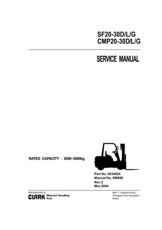
  • 1. SERVICE MANUAL RATED CAPACITY : 2000~3000kg SF20-30D/L/G CMP20-30D/L/G #40–1, Ungnam-Dong, Changwon-City,Kyungnam, Korea Part No. 8034924 Manual No. SM688 Manufactured by Rev.2 Mar,2004
  • 2. 1 FOREWORD This shop manual has been prepared as an aid to improve quality of repairs by giving the serviceman an accurate understanding of the product and by illustrating the correct way to perform repairs and make judgements. Make sure you understand the contents of this manual and use it to the full effect at every opportunity. This shop manual mainly contains the technical information necessary for operations performed in a service workshop. For ease of understanding, the manual is divided into sections for each main system of the machine, and the sections are further divided into groups. HOW TO READ THIS MANUAL CHAPTER AND SECTION This manual is issued as a guide to carrying out repair and maintenance. To easily understand this manual it is divided as follows : Example) 10 – 01 Section number (01 : Structure and function) Chapter number (10 : Engine) FOREWORD G E N E R A L 00 02 • Improper operation and maintenance of this machine could result in serious injury or death. • Read the Operation and Maintenance Manual carefully BEFORE operating the machine. • Always keep the Operation and Maintenance Manual and Parts catalogue near the work area. • Obey precautions concerning flammable liquids, hazardous fluids, oils, lubricants and cleaning solvents. • To prevent injury to workers, this symbol is used to mark safety precautions in this manual. The precautions accompanying this symbol should always be followed carefully. • The specifications contained in this shop manual are subject to change at any time and without any advance notice. Contact your SAMSUNG distributor for the latest information. ! SAFETY!
  • 3. 2 PAGE Page numbering is started from each section. Therefore, revised pages can be easily inserted. Also, additional pages and revision number can be indicated. Ex) 15 – 1 ③ 3rd revision Additional page from page 15 15th page of the section For the revision status in this manual, refer to REVISION HISTORY. SYMBOLS The following symbols as defined below are used in this manual to convey the intent of the instructions concerning safety and repair. FOREWORD G E N E R A L 00 02 Symbol Item Remarks Safety Caution Tightening torque Tool Adhesive Lubricating Special safety precautions are necessary when performing the work. Special technical precautions or other precautions for preserving standards are necessary when performing the work. Places that require special attention for the tightening torque during assembly. Places that require proper tools used in assembling and disassembling. Places to be applied with adhesive. Places where oil or lubricant must be added. !
  • 4. 1 SAFETY G E N E R A L 00 03 GENERAL PRECAUTIONS SAFETY PRECAUTIONS • When carrying out any operation or maintenance, have trained and experienced personnel carry out the work. • When carrying out any operation or maintenance, carefully read the Operation and Maintenance Manual. Read all the precautions given on the decals which are fixed to the machine. SAFETY DEVICE • Make sure that all guards and covers are mounted in their proper position. Repair or replace if damaged. • Pay attention to the method of using any safety locking device or safety belt. SAFETY CLOTHES AND HELMET • Wear the specified work clothes in the correct manner. • Use the specified protective gear (helmet, safety glasses, safety shoes, mask, gloves). Guard against injury from flying pieces of metal or debris, wear goggles, gloves and helmet. Always have a trained and experienced welder carry out any welding work. When carrying out welding work, always wear welding gloves, apron, glasses, cap and other clothes suitable for welding work. EX048 W A R N I N G! SERIOUS OR FATAL INJURY MAY RESULT TO YOURSELF OR OTHERS IF NOT FOLLOWED This fork lift should not be operated by anyone who is not authorized and properly trained. Read the Operators Manual carefully, and make yourself familiar with your fork lift. Inspect and check your fork lift daily before and after use. Do not operate a faulty or damaged fork lift. Repair work should be done by authorized and trained persons only. To protect from falling objects, make sure that the Overhead Guard and Load Backrest are correctly mounted and in good condition. Before starting engine, always set forward/reverse lever in neutral, with hand brake on. Drive carefully, keeping forks and attachments as low as possible & fully tilted back. Keep a careful lookout for people, obstructions and the path of travel. Watch clearance, especially overhead and tail swing. Do not stick hands, feet and other parts of your body outside the Operatorls compartment. Drive forward when you are climbing a slope with a load. Drive in reverse when you are descending with loads. Do not turn while on a slope. Slow down before turning. Avoid any sudden start, stop or turning. Lateral tipover can occur if the fork lift is improperly operated. Do not load fork lift over capacity limit designated on the load chart. Do not lift unstable loads. This fork lift is not designed for raising or transporting people. Do not use fork lift for those purposes under any circumstances. Before you get off fork lift, make sure the hand brake is set, lower forks or attachments, put forward/reverse lever in neutral position and turn off key switch. Do not park on a slope. P/NO.6092-13130
  • 5. 2 SAFETY G E N E R A L 00 03 PREPARE FOR EMERGENCIES • Know where fire extinguishers are located and how to use them. • Keep a first aid kit and an eye wash kit near the work area. • Keep emergency numbers for doctors, ambul- ance service, hospital, and fire department near your telephone. HANDLE FLUIDS SAFELY–AVOID FIRES • Handle fuel with care it is highly flammable. • Do not refuel the machine while smoking or when near open flame or sparks. Always stop the engine before refueling machine. Fill the fuel tank outdoors. • Store flammable fluids away from fire hazards. Do not incinerate or puncture pressurized containers. DISPOSE OF FLUIDS PROPERLY • Improperly disposing of fluids can harm the environment and ecology. Before draining any fluids, find out the proper way to dispose of waste from your local environmental agency. • Catch draining fuel, oil, or other fluids in suitable containers. Do not use food or beverage containers that may mislead someone into drinking from them. Wipe up spills at once. • Do not pour oil into the ground, down a drain, or into a stream, pond, or lake. Observe relevant environmental protection regulations when disposing of oil, fuel, coolant, brake fluid, filters, batteries, and other harmful waste. EX036 EX028 EX043
  • 6. 3 SAFETY G E N E R A L 00 03 AVOID HARMFUL ASBESTOS DUST • Avoid breathing dust that may be generated when handling components containing asbestos fibers. Inhaled asbestos fibers may cause lung cancer. EX025
  • 7. 4 SAFETY G E N E R A L 00 03 PREPARATIONS FOR WORK WARN OTHERS OF SERVICE WORK • Unexpected machine movement can cause serious injury. • Before performing any work on the machine, attach a “Do Not Operate” tag to the steering wheel or the right control lever. • When carrying out any operation with two or more workers, always agree on the operating procedure before starting. USE TOOLS PROPERLY • Use a tool only for its designed application. • Keep all tools in good condition and know the correct way to use them. • Decide on a place in the repair workshop to keep tools and removed parts. • Always keep the work area clean and make sure that there is no dirt or oil on the floor. • Before adding oil or making any repairs, park the machine on hard, level ground and put blocks under the wheels or tracks to prevent the mahcine from moving. • Before starting work, lower the forks or any other work equipment to the ground. • Turn the engine OFF, remove the start key, and apply the parking brake. • Illuminate your work area adequately but safely. Use a portable safety light for working inside or under the machine. Make sure the bulb is enclosed by a wire cage. The hot filament of an accidentally broken bulb can ignite spilled fuel or oil. EX033 EX042
  • 8. 5 SAFETY G E N E R A L 00 03 USE HANDHOLDS AND STEPS • Do not jump onto or down from the fork lift. • When getting on or off the fork lift, use the step provided. • Do not grasp an operating lever or steering wheel when getting on or off. • Always keep the step clean and repair it if damaged. • Never operate with wet or oily hands and feet. OPERATE FROM THE OPERATOR’S SEAT • Do not operate the fork lift from any place other than the designated operator’s position. • Improper seating may cause serious injury. FX019 FX020 FX019 FX020
  • 9. 1 CONSTRUCTION Power flow is from torque converter turbine, to turbine (clutch) shaft and gears, then through either forward gear or reverse idler shaft, to the output gear mounted on final drive pinion shaft. Transmission and differential are housed in a one–piece transmission case. Torque converter housing joined to transmission case through an adaptor (or spacer) plate holds the converter stator support and reverse idler outer bearing. Pump drive is from converter impeller hub gear, through an idler gear to the pump gear mounted on charging pump shaft. Final drive pinion gear shaft, mounted in tapered roller bearings at both ends in transmission case, is adjusted for mounting distance, and ring and pinion gear contact by, shim a pack installed behind the pinion gear inner tapered roller bearing cup in the transmisson case. Pinion shaft bearing preload is adjusted with shims behind outer bearing cone on the pinion shaft. STRUCTURE AND MAINTENANCE T R A N S A X L E 20 01 TA18 Transaxle assembly includes: • Torque converter • Single–speed forward and reverse powershift transmission with integral differential and drive axle • Full–floating straight drive axle • Automotive–type drum and shoe brakes • Gear–driven pump drive • Electric shift control, hydraulic inching control
  • 10. 2 Final drive ring gear is bolted to differential carrier. Differential support is by opposed tapered roller bearings mounted on inner end of wheel end housings, which are bolted to openings in transmission case at the sides of the differential. Differential bearing preload and ring gear clearance (backlash) is maintained by shims placed behind differential bearing cones on wheel end housings. Adjustment of differential bearing preload or ring gear backlash requires trial assembly, checking, and disassembly of wheel end housings until correct adjustment is obtained. Drive axle wheel hubs/brake drums are supported by double tapered roller bearings on outer end of wheel end housings. Drive axle shaft flange bolted to wheel hubs are full–floating in differential. Service brake backing plates are bolted to mounting flanges on wheel end housings. Wheel bearings are lubricated from the transaxle sump. Control valve is mounted on pad at top of transmission case. Oil from charging pump flows via filter and pressure regulator to control valve through an external oil supply line. Oil from control valve is delivered to clutches through passages in housing and oil distributor sleeve and seal rings at forward–clutch end of turbine/clutch shaft. Excess pump oil volume and converter–out oil, flows to oil cooler and returns to transmission housing at base of control valve, then through center of turbine/clutch shaft back to converter. HYDRAULIC CIRCUIT STRUCTURE AND MAINTENANCE T R A N S A X L E 20 01
  • 11. 3 SERVICE MAINTENANCE SERVICE The transaxle has two service openings: 1. Dipstick / oil fill tube in central side axle housing. 2. Drain plug, in bottom of transmission case. FLUID LEVEL CHECK Check the transaxle fluid level with: • Fork lift on a level surface • Engine idling with transmission in NEUTRAL • Oil at operating temperature 82~93°C (180~200°F) ① Remove the transaxle oil level plug the front of central housing of driving wheel. ② The oil level is correct when the oil reaches the full mark on dipstick. ③ Add recommended fluid only, as required. FLUID AND FILTER CHANGE It is recommended to: • Drain and replace the transaxle fluid every 1000 operating hours. • The oil should be drained when warmed to operating temperature, 82~93°C (180~200°F) • Replace the transaxle oil filter every 500 operating hours. See NOTICE below. IMPORTANT When the transaxle is new or rebuilt, it is recommended to change the oil filter after the first 50 hours and again after 100 operating hours. ① Remove drain plug from bottom of transmission case. Drain old oil into suitable drain pan. ② Remove old oil filter. The oil filter is mounted near the top of converter housing above transmission. ! STRUCTURE AND MAINTENANCE T R A N S A X L E 20 01
  • 12. 4 Take special care when removing the filter to avoid oil remaining in filter from draining onto floor. Loosen the filter using a filter wrench. Remove filter while holding a pad of cloth or other absorbent material under the open end to absorb any excess oil that may drain out of filter. ③ Install a new oil filter. Follow the installation instructions printed on filter. Always use genuine SAMSUNG parts REFILLING THE TRANSAXLE After drive axle and transmission housing has drained completely, • Install drain plug. • Loosen the oil level plug and fill the oil upto the plug hole. • Start the engine and run at idle speed (700~800 rpm) in NEUTRAL for 2~3 minutes to prime the converter and cooler lines. • Recheck oil level with engine running at idle speed. [82~93°C (180~200°F)] • Check for leaks at drain plug and oil filter. SPECIFICATION PRESSURE SPECIFICATION • Regulator valve pressure : 1108~1451kPa (160~210 psi) @ 1800 rpm Check Point : Oil supply line at converter • Converter In/Lube Pressure : 176~314kPa (26~45 psi ) @ 1800 rpm Check Point : Return from cooler • Converter Safety Valve Pressure : 729~827kPa (105~120 psi) @ (Trans in NEUTRAL) 1800 rpm (Refefence only) Check Point : None with line to cooler blocked • Clutch Pressure : 1034kPa (150 psi) @ (Forward, Reverse applied) 700~800 rpm idle Check Point : At control valve Normally 103kpa (15 psi) less than regulator (1/8 NPTF) pressure 1000kpa (145 psi min) • Clutch Pressure : Regulator pressure (in NEUTRAL) ! ! STRUCTURE AND MAINTENANCE T R A N S A X L E 20 01
  • 13. 5 NOTES • All rpm’s noted are engine speed. • All clutch pressures are at engine idle speed with clutch engaged, unless otherwise noted. • Oil at operating temperature 82~93°C (180~200°F) • Refer to following illustrations for check point locations. PRESSURE CHECK POINTS ! STRUCTURE AND MAINTENANCE T R A N S A X L E 20 01
  • 14. 6 STRUCTURE AND MAINTENANCE T R A N S A X L E 20 01 SERVICE BRAKE ADJUSTMENT PREPARATION 1. The service brakes on the transaxle may be adjusted from the inner side through the backing plate (all models), or from the outer side through access openings in the wheel hub/brake drum (later models). 2. Brake clearance is measured between brake shoe and drum, with brakes fully released. Brake clearance : 0.255~0.304 mm (.010~.012 in) CAUTION : Be sure transmission directional control is in NEUTRAL and fork lift prevented from moving when parking brake is released. 3. Release parking brake. IMPORTANT – Do not overtighten brakes. It is very difficult to release the ratchet wheel pawl and back off adjustment of the brake. ! !
  • 15. STRUCTURE AND MAINTENANCE T R A N S A X L E 7 20 01 ADJUSTMENT AT BACKING PLATE 1. Remove the 4 dust plugs in brake backing plate. 2. Use a feeler (thickness) gauge to check the clearance between each shoe and drum. Use a brake adjuster tool to rotate the adjuster ratchet wheel in the brake. 3. Use a screwdriver to push on and release the ratchet pawl when it is necessary to back off adjustment (increase clearance) of the brake. 4. Carefully adjust clearance between brake shoes and drum to 0.255~0.304 mm (.010~.012 in) measured at dust plug openings at outer sides of backing plate. 5. Replace the dust plugs in brake backing plate when adjustment is completed. ADJUSTMENT AT WHEEL HUB Openings in the wheel hub/brake drum have been provided for easier access to check and adjust the service brakes from the outer side. Requires removal of drive wheel and tire assembly. Some models may have only a slot for measuring brake clearance ; adjustment is made through the plug openings on backing plate. Later models have a slot and circular opening for access also to the adjuster. The opening is enclosed with a dust cover held in place by a single screw. 1. Remove wheel and tire assembly from wheel hub. WARNING–Pneumatic Tire Wheels Before loosening wheel mounting bolts or nuts, release the air pressure from the tire. Failure to release the air pressure from the tire can result in serious injury or death. 2. Remove dust cover from access opening in wheel hub/brake drum. 3. Use feeler (thickness) gauge to check the clearance between each shoe and drum. Use a brake adjuster tool to rotate the adjuster ratchet wheel in the brake. 4. Use a tool with a hook to pull on and release the ratchet pawl when it is necessary to back off adjustment (increase clearance) of the brake. !
  • 16. 8 IMPORTANT – Do not overtighten brakes. It is very difficult to release the ratchet wheel pawl and back off adjustment of the bake. 5. Carefully adjust clearance between brake shoes and drum to 0.255~0.304 mm (.010~.012 in) measured at slot opening. Move slot by rotating brake drum to check clearance at the illustrated position for each brake shoe. (20–01–6) 6. After adjusting brakes, install dust cover over access opening in the wheel hub. 7. Install wheel and tire assembly on the drive axle wheel hub. 8. Install wheel mounting lug nuts and tighten to spec : 637~718 Nm (471~531 lbf·ft) ! STRUCTURE AND MAINTENANCE T R A N S A X L E 20 01
  • 17. 1 SERVICE BRAKE ADJUSTMENT T R A N S A X L E 20 02 PRECAUTION • Before attempting any repairs or overhaul of this assembly, please read through the entire disassembly and assembly procedures first. Cleanliness is of extreme importance in the repair and overhaul of this assembly. • The exterior surface of the unit MUST be thoroughly cleaned of all dirt and foreign substances to prevent contamination of the parts during disassembly and overhaul. Perform all disassembly and assembly work in a clean area. Protect all components from dust and dirt while repairs are being made. • Keep all parts in order as disassembly progresses. Take care to properly identify each part and its order of removal. If necessary, keep notes and put marking on parts using a nondestructive marker such as a felt–tipped pen. REMOVE AUXILIARY SUBASSEMBLIES 1. Remove torque converter assembly by carefully sliding it off the turbine (clutch) shaft and stator support. 2. Disassemble converter drive plate and adaptor, as needed. Remove the : 3. Oil filter 4. Charging pump 5. Oil supply line assembly 6. Transmission control valve assembly !
  • 18. 2 SERVICE BRAKE ADJUSTMENT T R A N S A X L E 20 02 WHEEL END 1. Loosen and remove the axle shaft fasteners. 2. Remove axle shaft. 3. Unbend (straighten) the lockplate tabs from the bolt heads of the wheel bearing retainer plate fasteners. 4. Remove the bearing retainer plate fasteners. 5. Remove the lockplate, bearing retainer plate and wheel bearing shims. 6. Pull wheel hub out to loosen bearing (you may have to tap on hub or pry at brake backing plate), remove outer wheel bearing, then remove the wheel hub/brake drum assembly with inner wheel bearing and oil seal. 8 7 4 6 5 3 2 1
  • 19. 3 SERVICE BRAKE ADJUSTMENT T R A N S A X L E 20 02 IMPORTANT This oil seal is a type that seals internally, and is lined with sealing compound on the inner diameter that sticks and seals to the spindle. Removing the wheel hub from the spindle breaks that seal. Replace with new seal each time that the wheel hub is removed from wheel end housing. 7. Before removal of wheel end housing, mark the housing and the transmission case for same–location matching at reassembly. Loosen and remove the housing bolts and washers. 8. Remove wheel end housing from transmission case. 9. If the differential bearing on the inner end of the wheel end housing is to be removed and replaced, use a bearing puller, if necessary. Wire bearing shims to wheel end housing for storage until reassembly. 10. Repeat procedures of Steps 1 through 9 for opposite wheel end disassembly. 11. Remove the differential assembly from transmission case. !
  • 20. Thank you very much for your reading. Please Click Here. Then Get COMPLETE MANUAL. NO WAITING NOTE: If there is no response to click on the link above, please download the PDF document first and then click on it.
  • 21. 4 SERVICE BRAKE ADJUSTMENT T R A N S A X L E 20 02 BRAKE ASSEMBLY REMOVAL Brake removal is optional for brake overhaul as necessary. 1. Remove the upper brake shoe return springs. 2. Remove lower return spring. 3. Remove brake shoe hold–down (guide) springs. 4. Disconnect parking brake cable. Remove the brake shoes. 5. Remove brake backing plate fasteners and washers. 6. Remove backing plate and parking brake cable assembly from wheel end housing. 7. Remove drive axle support and spacer from wheel end housing.
  • 22. 5 SERVICE BRAKE ADJUSTMENT T R A N S A X L E 20 02 SEPARATION OF CONVERTER HOUSING AND ADAPTOR PLATE 1. Remove the fasteners and washers which mount the converter housing to transmission case through the adaptor plate. 2. From other side, remove the bolts and washers which mount adaptor (spacer) plate to converter housing. 3. Remove the clutch pressure–regulating valve assembly (also oil filter mounting base). IMPORTANT Pry only at the dowel pins to remove adaptor plate. Dowel pins must be removed before reassembly. See later instructions. 4. Separate converter housing from adaptor plate. 5. Remove impeller hub gear from stator support. 6. Remove pump drive idler gear and bearing, outer and inner thrust washers, and idler shaft. 7. Remove adaptor plate from transmission case. !
  • 23. 6 SERVICE BRAKE ADJUSTMENT T R A N S A X L E 20 02 STATOR SUPPORT REMOVAL FROM ADAPTOR PLATE 1. The stator support is held in place by two retaining rings, one on each side of the adaptor plate. 2. To remove stator support : – Remove front (converter end) retaining ring from ring groove and move ring and impeller gear thrust washer toward stator support seal surface. – Push stator support to the rear (towards transmission side) far enough to expose rear retainer ring. – Remove rear retaining ring. – From the front, pull stator support from adaptor plate. CLUTCH ASSEMBLY, IDLER GEAR & PINION SHAFT REMOVAL 1. Move the reverse idler gear and clutch assembly apart far enough to allow the idler shaft to be pulled out of the inner bearing.