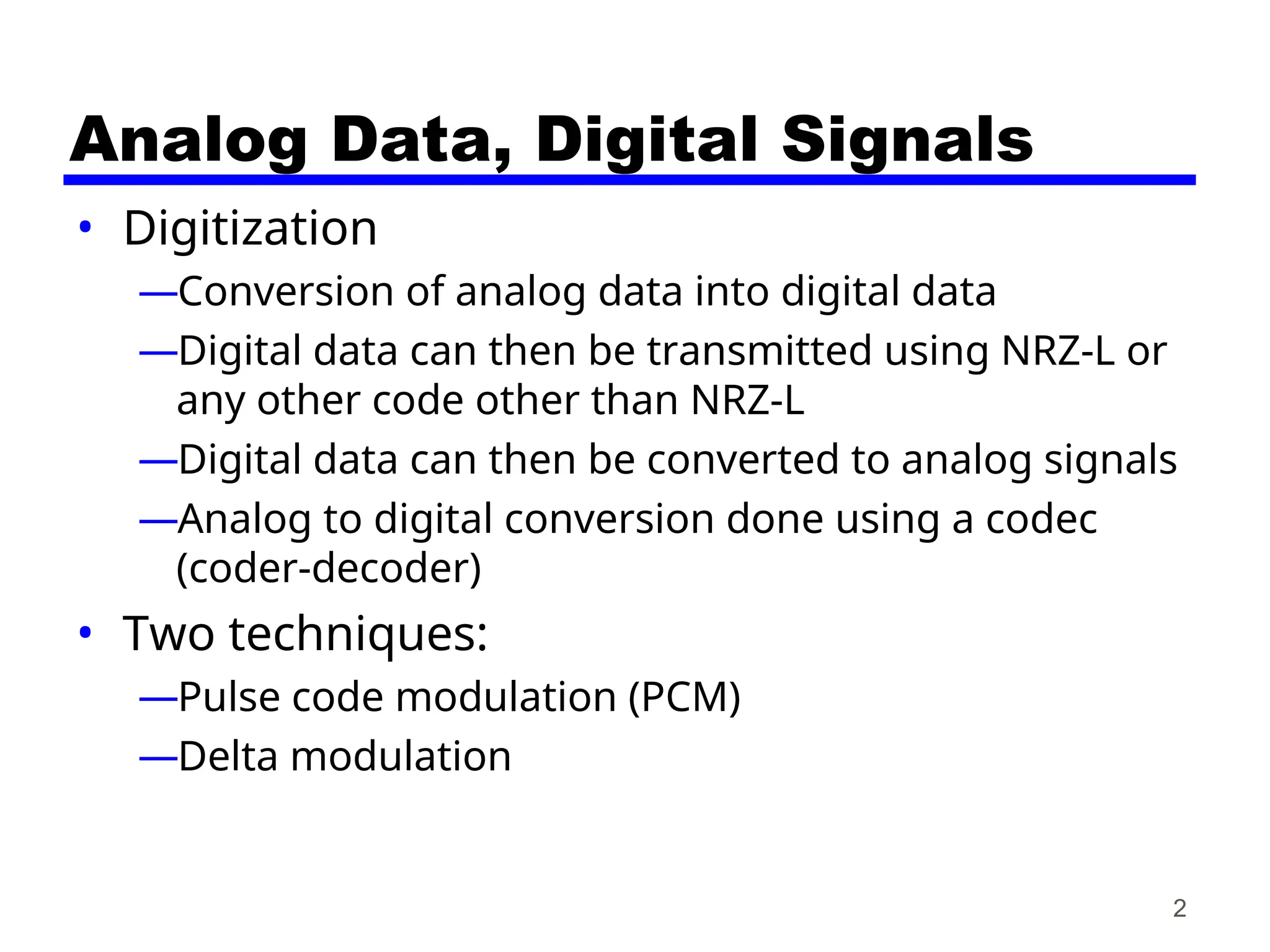
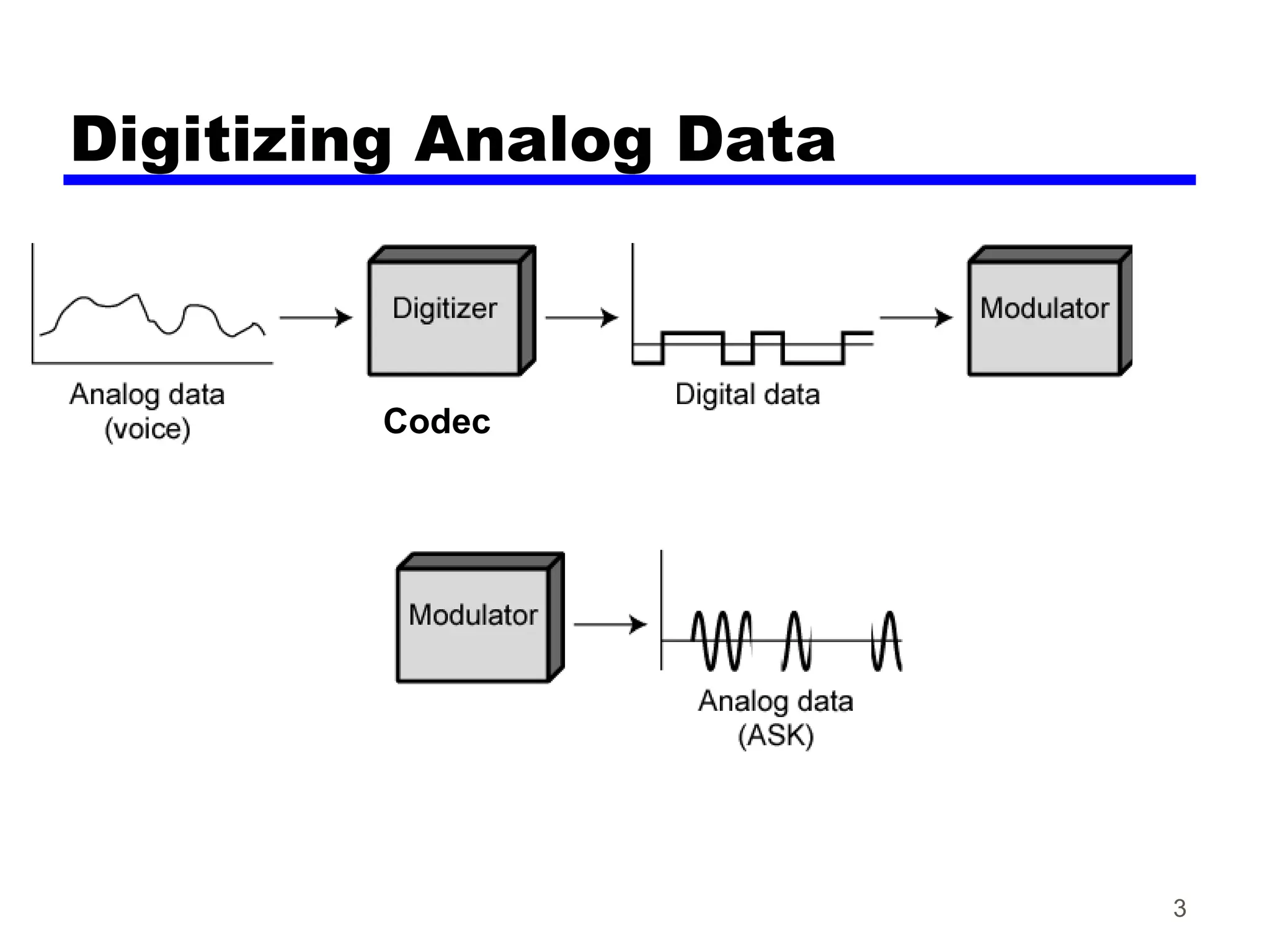
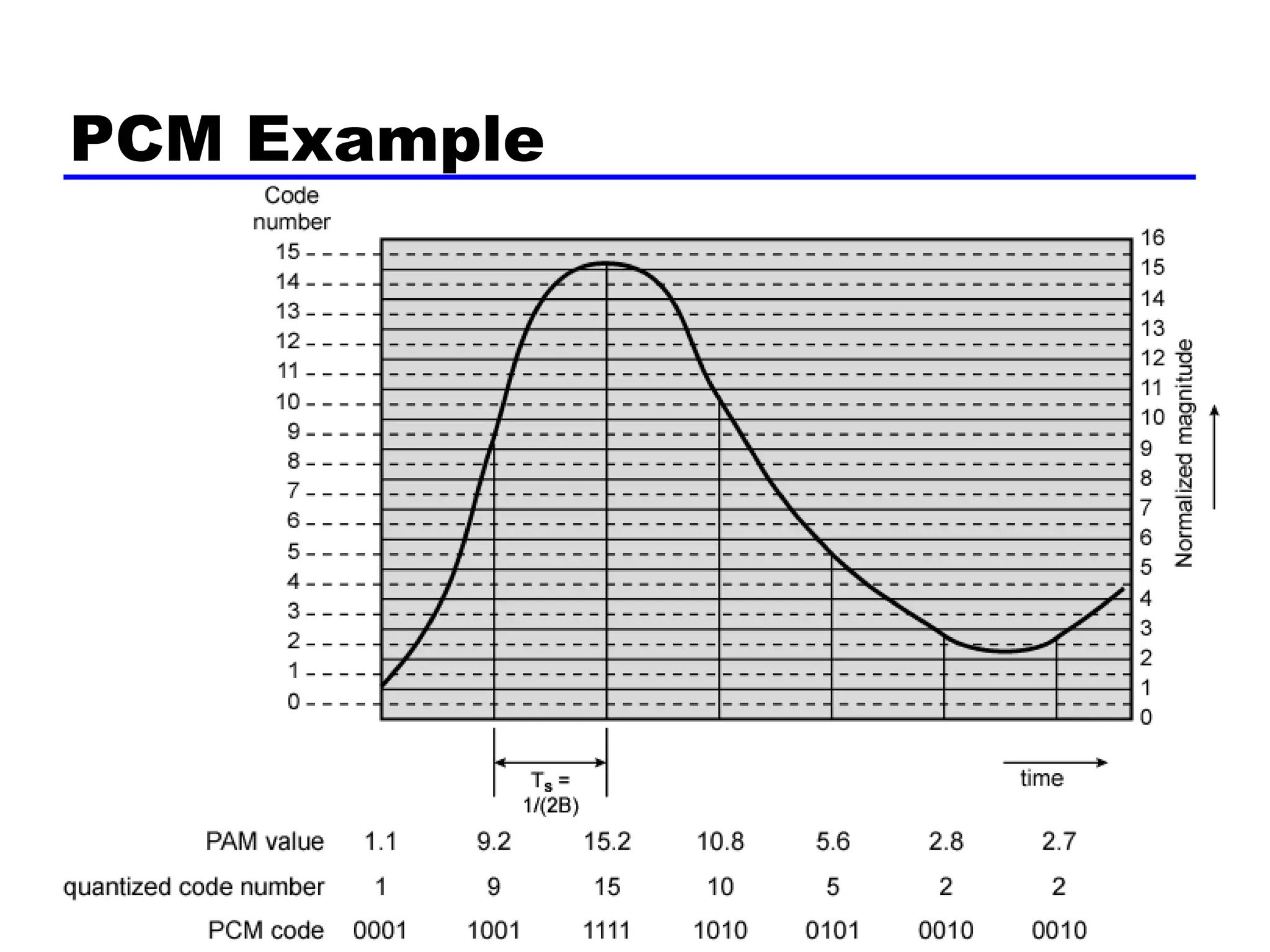
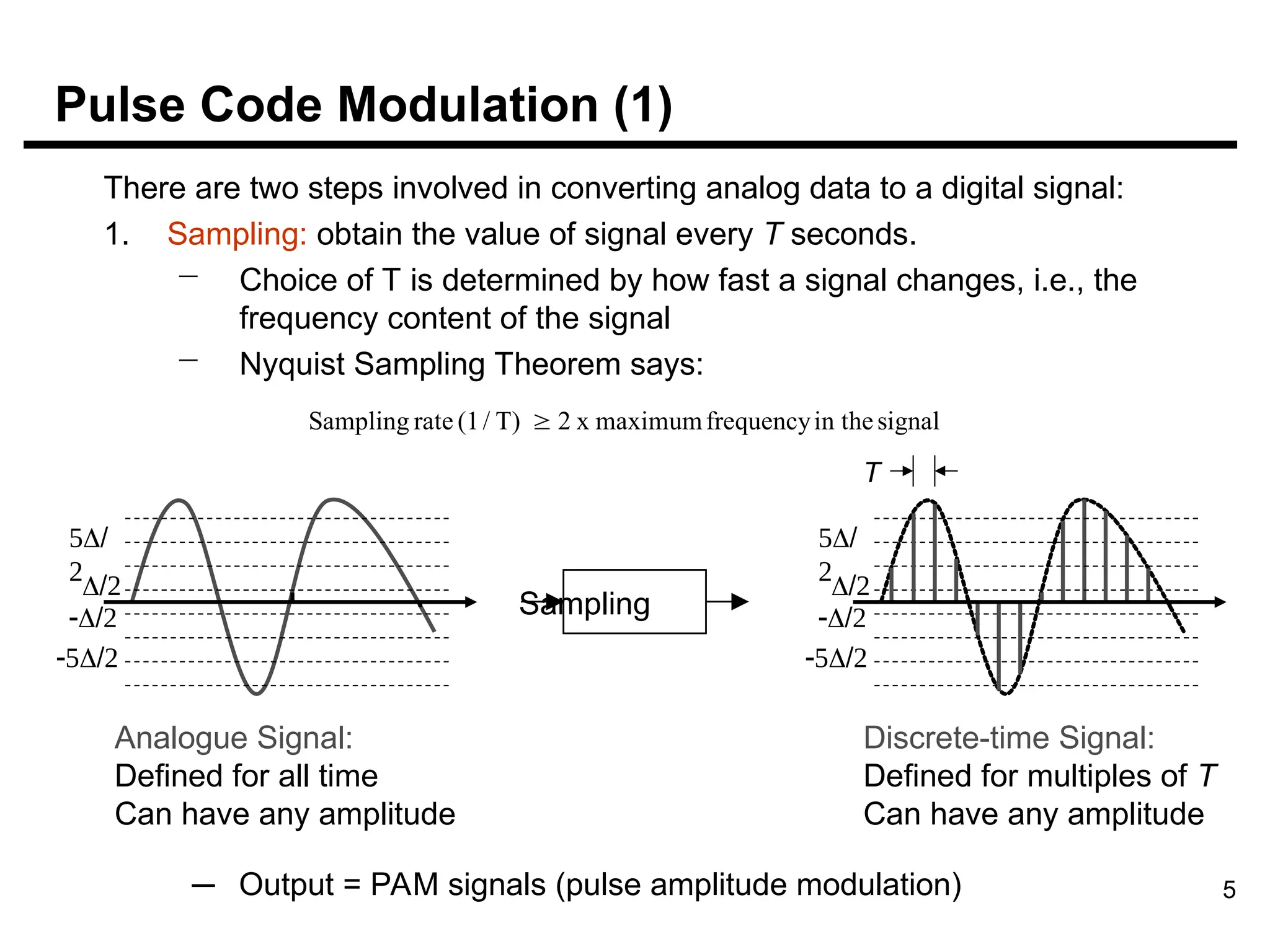
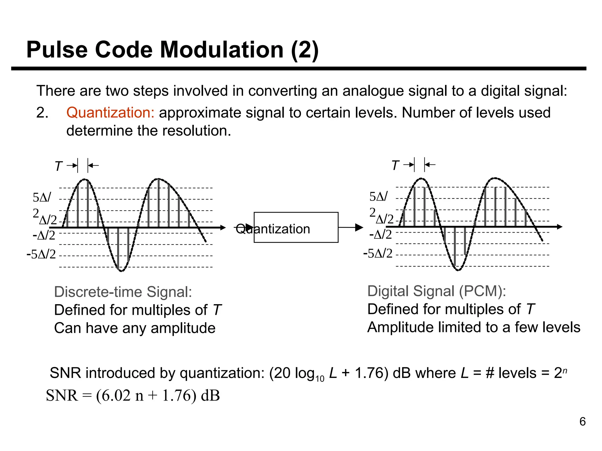
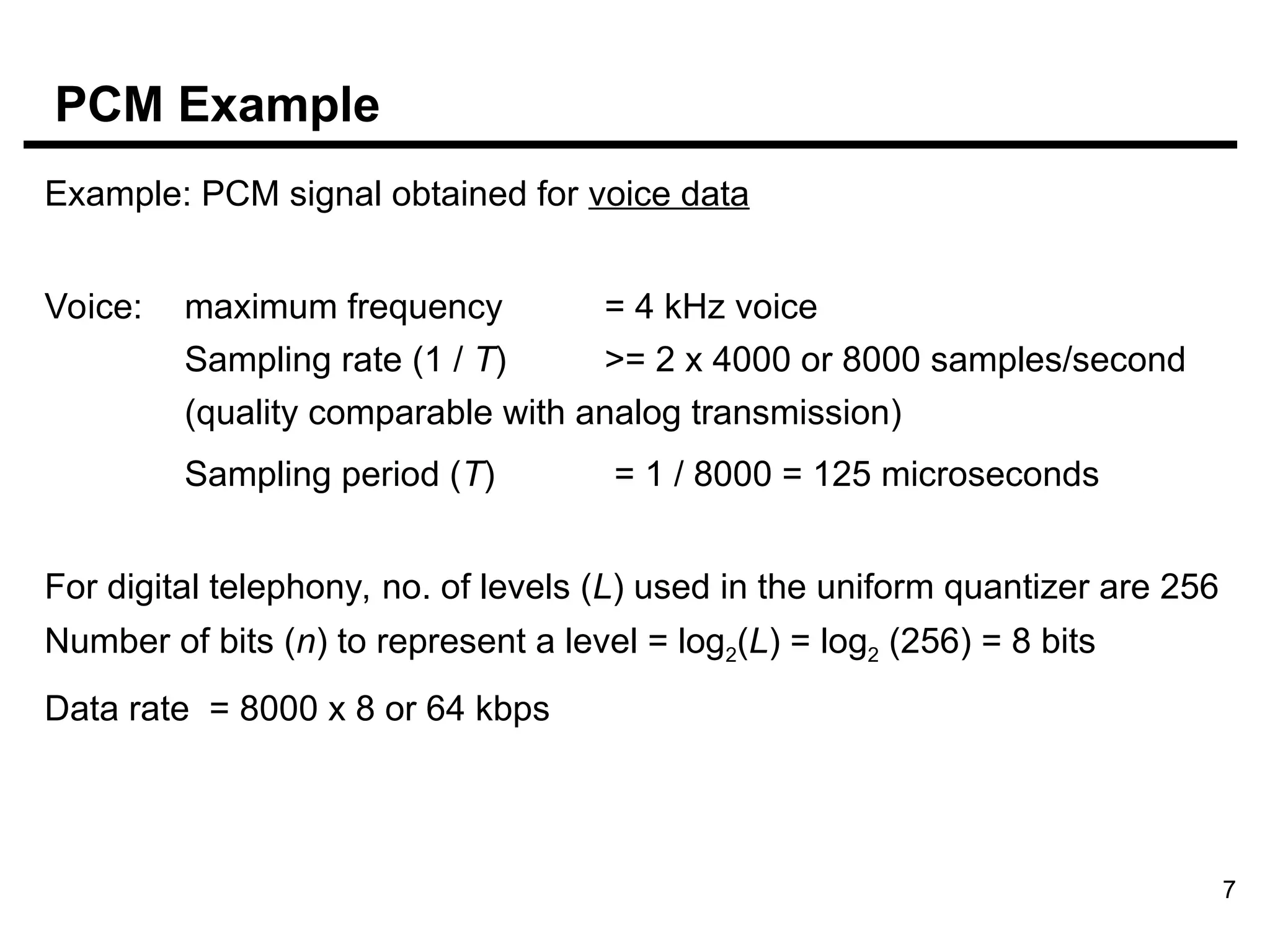
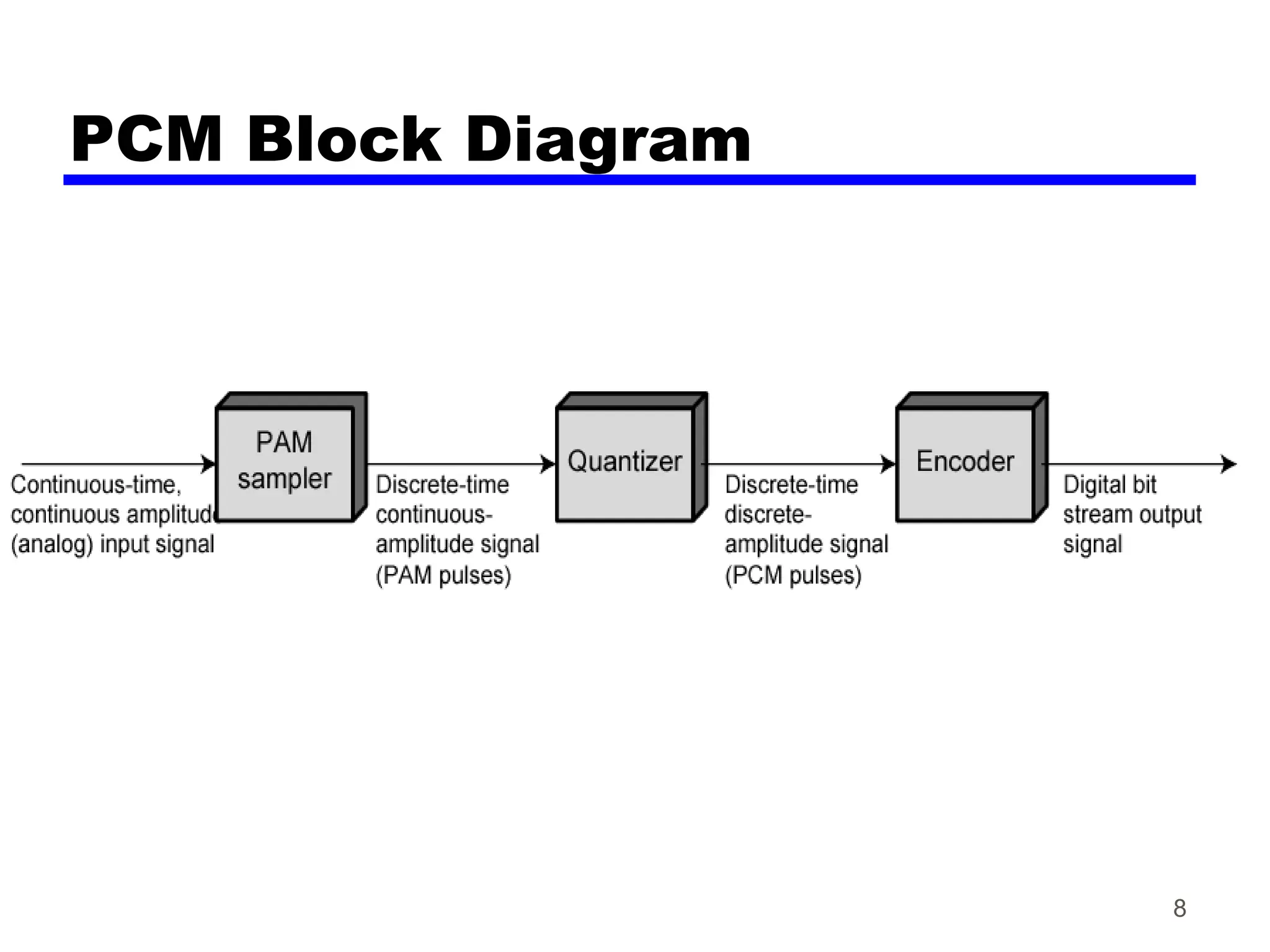
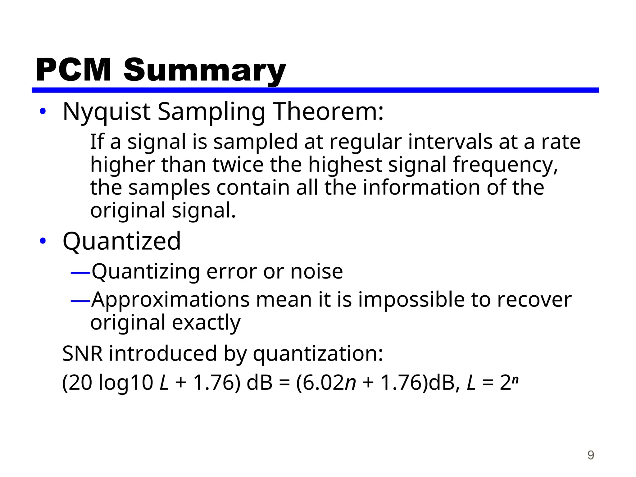
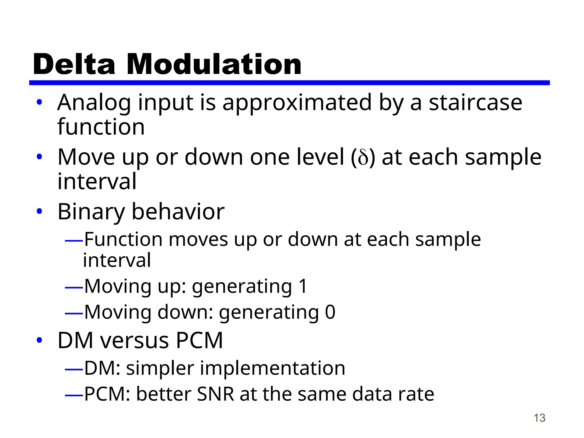
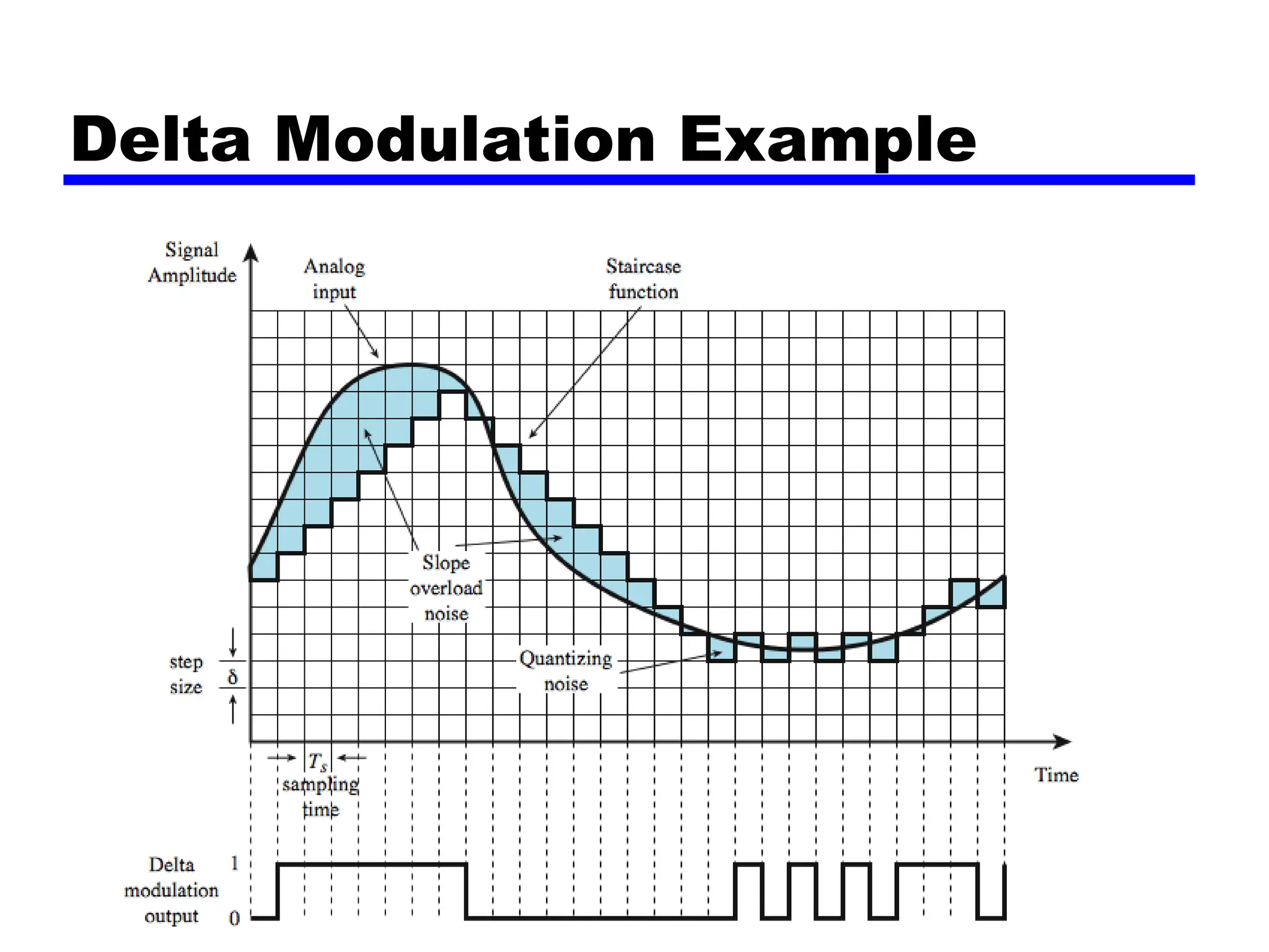
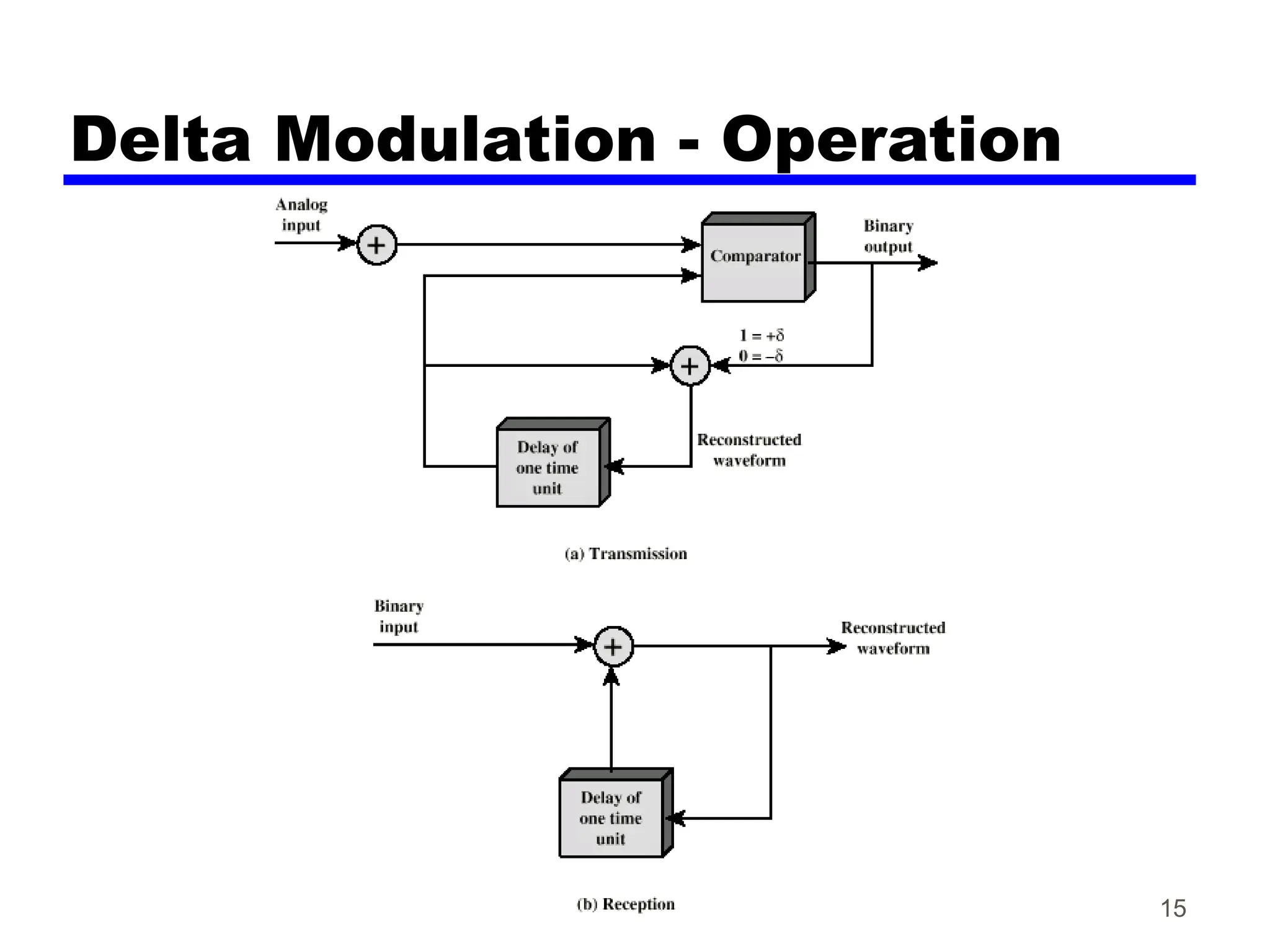
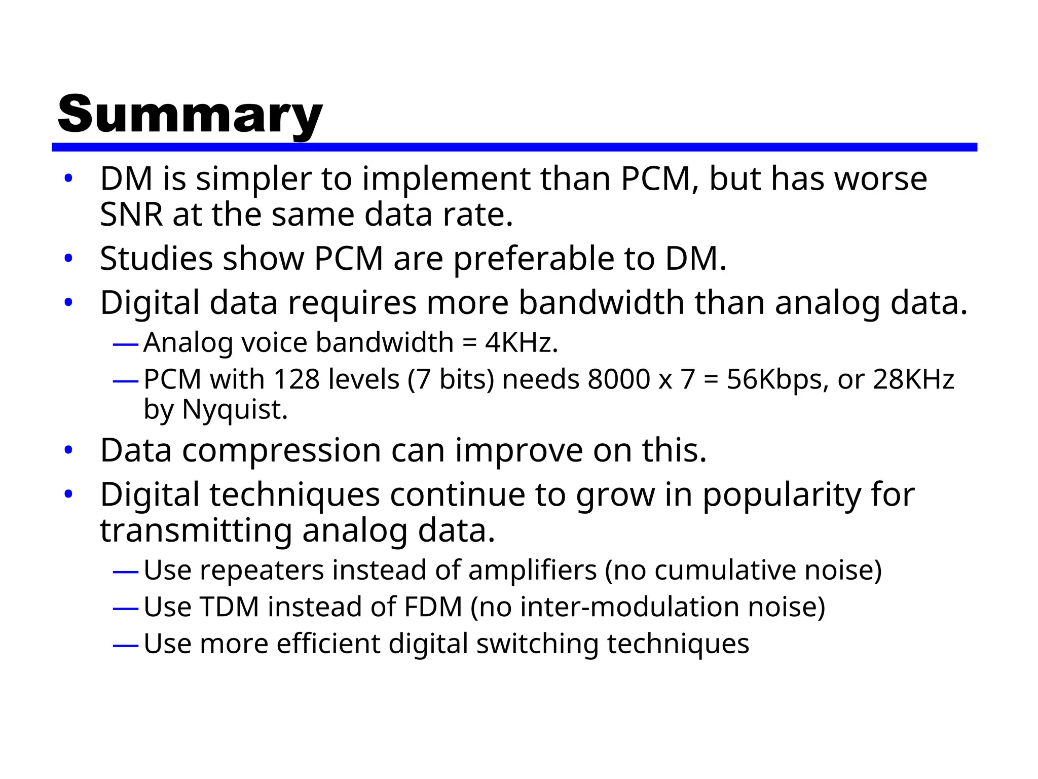
11/07/24 09:52 1
Data Encoding ─
Analog Data,
Digital Signals (5.3)
CSE 3213
Fall 2011
2
Analog Data, Digital Signals
• Digitization
—Conversion of analog data into digital data
—Digital data can then be transmitted using NRZ-L or
any other code other than NRZ-L
—Digital data can then be converted to analog signals
—Analog to digital conversion done using a codec
(coder-decoder)
• Two techniques:
—Pulse code modulation (PCM)
—Delta modulation
3
Digitizing Analog Data
Codec
4
PCM Example
5
Pulse Code Modulation (1)
There are two steps involved in converting analog data to a digital signal:
1. Sampling: obtain the value of signal every T seconds.
 Choice of T is determined by how fast a signal changes, i.e., the
frequency content of the signal
 Nyquist Sampling Theorem says:
signal
in the
frequency
maximum
x
2
T)
/
(1
rate
Sampling 
Sampling





Analogue Signal:
Defined for all time
Can have any amplitude





Discrete-time Signal:
Defined for multiples of T
Can have any amplitude
T
─ Output = PAM signals (pulse amplitude modulation)
6
Pulse Code Modulation (2)
There are two steps involved in converting an analogue signal to a digital signal:
2. Quantization: approximate signal to certain levels. Number of levels used
determine the resolution.
Quantization 




Digital Signal (PCM):
Defined for multiples of T
Amplitude limited to a few levels
T





Discrete-time Signal:
Defined for multiples of T
Can have any amplitude
T
SNR introduced by quantization: (20 log10 L + 1.76) dB where L = # levels = 2n
SNR = (6.02 n + 1.76) dB
7
PCM Example
Example: PCM signal obtained for voice data
Voice: maximum frequency = 4 kHz voice
Sampling rate (1 / T) >= 2 x 4000 or 8000 samples/second
(quality comparable with analog transmission)
Sampling period (T) = 1 / 8000 = 125 microseconds
For digital telephony, no. of levels (L) used in the uniform quantizer are 256
Number of bits (n) to represent a level = log2(L) = log2 (256) = 8 bits
Data rate = 8000 x 8 or 64 kbps
8
PCM Block Diagram
9
PCM Summary
• Nyquist Sampling Theorem:
If a signal is sampled at regular intervals at a rate
higher than twice the highest signal frequency,
the samples contain all the information of the
original signal.
• Quantized
—Quantizing error or noise
—Approximations mean it is impossible to recover
original exactly
SNR introduced by quantization:
(20 log10 L + 1.76) dB = (6.02n + 1.76)dB, L = 2n
10
Nonlinear Encoding
• Quantization levels not evenly spaced
• Reduces overall signal distortion
• Can also be done by companding
(compressing-expanding) the input analog
signal
—Significantly improves the PCM SNR ratio
Non-Linear Coding
Companding
13
Delta Modulation
• Analog input is approximated by a staircase
function
• Move up or down one level () at each sample
interval
• Binary behavior
—Function moves up or down at each sample
interval
—Moving up: generating 1
—Moving down: generating 0
• DM versus PCM
—DM: simpler implementation
—PCM: better SNR at the same data rate
Delta Modulation Example
15
Delta Modulation - Operation
Summary
• DM is simpler to implement than PCM, but has worse
SNR at the same data rate.
• Studies show PCM are preferable to DM.
• Digital data requires more bandwidth than analog data.
—Analog voice bandwidth = 4KHz.
—PCM with 128 levels (7 bits) needs 8000 x 7 = 56Kbps, or 28KHz
by Nyquist.
• Data compression can improve on this.
• Digital techniques continue to grow in popularity for
transmitting analog data.
—Use repeaters instead of amplifiers (no cumulative noise)
—Use TDM instead of FDM (no inter-modulation noise)
—Use more efficient digital switching techniques
17
Reading
• Section 5.3, Stallings’ book
• Next time: sections 5.2 and 5.4

chapter_5 digital encoding data_part2.ppt

  • 1.
    11/07/24 09:52 1 DataEncoding ─ Analog Data, Digital Signals (5.3) CSE 3213 Fall 2011
  • 2.
    2 Analog Data, DigitalSignals • Digitization —Conversion of analog data into digital data —Digital data can then be transmitted using NRZ-L or any other code other than NRZ-L —Digital data can then be converted to analog signals —Analog to digital conversion done using a codec (coder-decoder) • Two techniques: —Pulse code modulation (PCM) —Delta modulation
  • 3.
  • 4.
  • 5.
    5 Pulse Code Modulation(1) There are two steps involved in converting analog data to a digital signal: 1. Sampling: obtain the value of signal every T seconds.  Choice of T is determined by how fast a signal changes, i.e., the frequency content of the signal  Nyquist Sampling Theorem says: signal in the frequency maximum x 2 T) / (1 rate Sampling  Sampling      Analogue Signal: Defined for all time Can have any amplitude      Discrete-time Signal: Defined for multiples of T Can have any amplitude T ─ Output = PAM signals (pulse amplitude modulation)
  • 6.
    6 Pulse Code Modulation(2) There are two steps involved in converting an analogue signal to a digital signal: 2. Quantization: approximate signal to certain levels. Number of levels used determine the resolution. Quantization      Digital Signal (PCM): Defined for multiples of T Amplitude limited to a few levels T      Discrete-time Signal: Defined for multiples of T Can have any amplitude T SNR introduced by quantization: (20 log10 L + 1.76) dB where L = # levels = 2n SNR = (6.02 n + 1.76) dB
  • 7.
    7 PCM Example Example: PCMsignal obtained for voice data Voice: maximum frequency = 4 kHz voice Sampling rate (1 / T) >= 2 x 4000 or 8000 samples/second (quality comparable with analog transmission) Sampling period (T) = 1 / 8000 = 125 microseconds For digital telephony, no. of levels (L) used in the uniform quantizer are 256 Number of bits (n) to represent a level = log2(L) = log2 (256) = 8 bits Data rate = 8000 x 8 or 64 kbps
  • 8.
  • 9.
    9 PCM Summary • NyquistSampling Theorem: If a signal is sampled at regular intervals at a rate higher than twice the highest signal frequency, the samples contain all the information of the original signal. • Quantized —Quantizing error or noise —Approximations mean it is impossible to recover original exactly SNR introduced by quantization: (20 log10 L + 1.76) dB = (6.02n + 1.76)dB, L = 2n
  • 10.
    10 Nonlinear Encoding • Quantizationlevels not evenly spaced • Reduces overall signal distortion • Can also be done by companding (compressing-expanding) the input analog signal —Significantly improves the PCM SNR ratio
  • 11.
  • 12.
  • 13.
    13 Delta Modulation • Analoginput is approximated by a staircase function • Move up or down one level () at each sample interval • Binary behavior —Function moves up or down at each sample interval —Moving up: generating 1 —Moving down: generating 0 • DM versus PCM —DM: simpler implementation —PCM: better SNR at the same data rate
  • 14.
  • 15.
  • 16.
    Summary • DM issimpler to implement than PCM, but has worse SNR at the same data rate. • Studies show PCM are preferable to DM. • Digital data requires more bandwidth than analog data. —Analog voice bandwidth = 4KHz. —PCM with 128 levels (7 bits) needs 8000 x 7 = 56Kbps, or 28KHz by Nyquist. • Data compression can improve on this. • Digital techniques continue to grow in popularity for transmitting analog data. —Use repeaters instead of amplifiers (no cumulative noise) —Use TDM instead of FDM (no inter-modulation noise) —Use more efficient digital switching techniques
  • 17.
    17 Reading • Section 5.3,Stallings’ book • Next time: sections 5.2 and 5.4

Editor's Notes

  • #2 In this section we examine the process of transforming analog data into digital signals. Analog data, such as voice and video, is often digitized to be able to use digital transmission facilities. Strictly speaking, it might be more correct to refer to this as a process of converting analog data into digital data; this process is known as digitization. Once analog data have been converted into digital data, a number of things can happen. The three most common are: 1. The digital data can be transmitted using NRZ-L. In this case, we have in fact gone directly from analog data to a digital signal. 2. The digital data can be encoded as a digital signal using a code other than NRZ-L. Thus an extra step is required. 3. The digital data can be converted into an analog signal, using one of the modulation techniques discussed in Section 5.2.
  • #3 Stallings DCC9e Figure 5.15 shows voice data that are digitized and then converted to an analog ASK signal. This allows digital transmission in the sense defined in Chapter 3. The voice data, because they have been digitized, can be treated as digital data, even though transmission requirements (e.g., use of microwave) dictate that an analog signal be used. The device used for converting analog data into digital form for transmission, and subsequently recovering the original analog data from the digital, is known as a codec (coder-decoder). In this section we examine the two principal techniques used in codecs, pulse code modulation and delta modulation. The section closes with a discussion of comparative performance.
  • #4 Stallings DCC9e Figure 5.16 shows an example in which the original signal is assumed to be bandlimited with a bandwidth of B. PAM samples are taken at a rate of 2B, or once every Ts = 1/2B seconds. Each PAM sample is approximated by being quantized into one of 16 different levels. Each sample can then be represented by 4 bits. But because the quantized values are only approximations, it is impossible to recover the original signal exactly. By using an 8-bit sample, which allows 256 quantizing levels, the quality of the recovered voice signal is comparable with that achieved via analog transmission. Note that this implies that a data rate of 8000 samples per second  8 bits per sample = 64 kbps is needed for a single voice signal.
  • #5 The simplest technique for transforming analog data into digital signals is pulse code modulation (PCM), which involves sampling the analog data periodically and quantizing the samples. Pulse code modulation (PCM) is based on the sampling theorem (quoted above). Hence if voice data is limited to frequencies below 4000 Hz (a conservative procedure for intelligibility), 8000 samples per second would be sufficient to characterize the voice signal completely. Note, however, that these are analog samples, called pulse amplitude modulation (PAM) samples. To convert to digital, each of these analog samples must be assigned a binary code.
  • #7 Stallings DCC9e Figure 5.16 shows an example in which the original signal is assumed to be bandlimited with a bandwidth of B. PAM samples are taken at a rate of 2B, or once every Ts = 1/2B seconds. Each PAM sample is approximated by being quantized into one of 16 different levels. Each sample can then be represented by 4 bits. But because the quantized values are only approximations, it is impossible to recover the original signal exactly. By using an 8-bit sample, which allows 256 quantizing levels, the quality of the recovered voice signal is comparable with that achieved via analog transmission. Note that this implies that a data rate of 8000 samples per second  8 bits per sample = 64 kbps is needed for a single voice signal.
  • #8 Thus, PCM starts with a continuous-time, continuous-amplitude (analog) signal, from which a digital signal is produced, as shown in Stallings DCC9e Figure 5.17. The digital signal consists of blocks of n bits, where each n-bit number is the amplitude of a PCM pulse. On reception, the process is reversed to reproduce the analog signal. Notice, however, that this process violates the terms of the sampling theorem. By quantizing the PAM pulse, the original signal is now only approximated and cannot be recovered exactly. This effect is known as quantizing error or quantizing noise. Each additional bit used for quantizing increases SNR by about 6 dB, which is a factor of 4.
  • #11 Typically, the PCM scheme is refined using a technique known as nonlinear encoding, which means, in effect, that the quantization levels are not equally spaced. The problem with equal spacing is that the mean absolute error for each sample is the same, regardless of signal level. Consequently, lower amplitude values are relatively more distorted. By using a greater number of quantizing steps for signals of low amplitude, and a smaller number of quantizing steps for signals of large amplitude, a marked reduction in overall signal distortion is achieved, as shown in Stallings DCC8e Figure 5.18. Nonlinear encoding can significantly improve the PCM SNR ratio. For voice signals, improvements of 24 to 30 dB have been achieved.
  • #12 The same effect can be achieved by using uniform quantizing but companding (compressing-expanding) the input analog signal. Companding is a process that compresses the intensity range of a signal by imparting more gain to weak signals than to strong signals on input. At output, the reverse operation is performed. Stallings DCC8e Figure 5.19 shows typical companding functions. Note that the effect on the input side is to compress the sample so that the higher values are reduced with respect to the lower values. Thus, with a fixed number of quantizing levels, more levels are available for lower-level signals. On the output side, the compander expands the samples so the compressed values are restored to their original values.
  • #13 A variety of techniques have been used to improve the performance of PCM or to reduce its complexity. One of the most popular alternatives to PCM is delta modulation (DM). With delta modulation, an analog input is approximated by a staircase function that moves up or down by one quantization level () at each sampling interval (Ts). The important characteristic of this staircase function is that its behavior is binary: At each sampling time, the function moves up or down a constant amount . Thus, the output of the delta modulation process can be represented as a single binary digit for each sample. In essence, a bit stream is produced by approximating the derivative of an analog signal rather than its amplitude: A 1 is generated if the staircase function is to go up during the next interval; a 0 is generated otherwise.
  • #14 Stallings DCC8e Figure 5.20 shows an example where the staircase function is overlaid on the original analog waveform. A 1 is generated if the staircase function is to go up during the next interval; a 0 is generated otherwise. The transition (up or down) that occurs at each sampling interval is chosen so that the staircase function tracks the original analog waveform as closely as possible. There are two important parameters in a DM scheme: the size of the step assigned to each binary digit, , and the sampling rate. As the above figure illustrates,  must be chosen to produce a balance between two types of errors or noise. When the analog waveform is changing very slowly, there will be quantizing noise. This noise increases as  is increased. On the other hand, when the analog waveform is changing more rapidly than the staircase can follow, there is slope overload noise. This noise increases as  is decreased. It should be clear that the accuracy of the scheme can be improved by increasing the sampling rate. However, this increases the data rate of the output signal.
  • #15 Stallings DCC9e Figure 5.21 illustrates the logic of the process, which is essentially a feedback mechanism. For transmission, the following occurs: At each sampling time, the analog input is compared to the most recent value of the approximating staircase function. If the value of the sampled waveform exceeds that of the staircase function, a 1 is generated; otherwise, a 0 is generated. Thus, the staircase is always changed in the direction of the input signal. The output of the DM process is therefore a binary sequence that can be used at the receiver to reconstruct the staircase function. The staircase function can then be smoothed by some type of integration process or by passing it through a low pass filter to produce an analog approximation of the analog input signal.