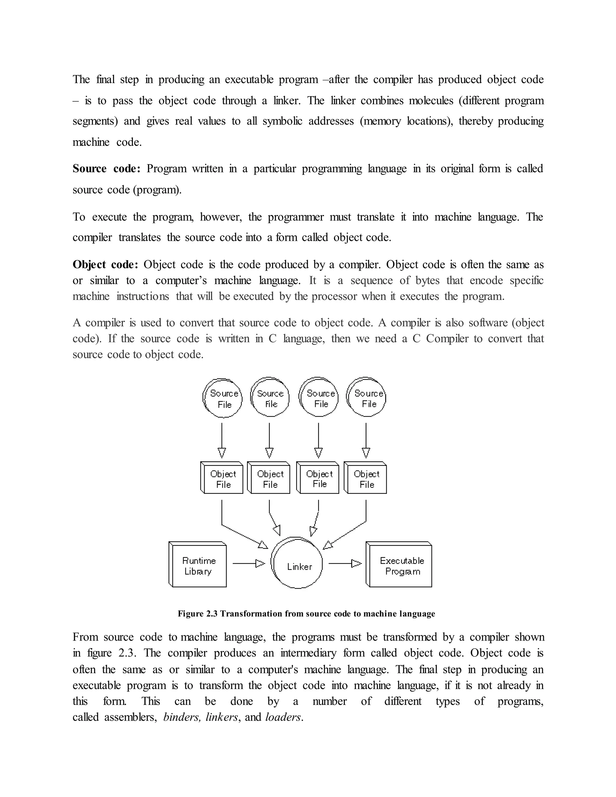
CHAPTER 2
INTRODUCTION
A computer is a general purpose device that can be programmed to carry out a finite set of
arithmetic or logical operations. Since a sequence of operations can be readily changed, the
computer can solve more than one kind of problem. It can perform wide variety of tasks like
receiving data, processing it, and producing useful results.
Computer works on a set of instructions called computer program, which clearly specifies the
ways to carry out a task. A computer takes instructions in the form of computer programs and
carries out the requested task.
Programming can be defined as the development of a solution to an identified problem, and the
setting up of a related series of instructions which, when directed through the computer
hardware, will produce the desired results.
2.1 Problem Solving Steps
Before starting the program of writing a program (coding), the programmer has to determine the
problem that needs to be solved. There are different approaches to problem solving. One
common technique is to use the program development cycle, with the number of steps that may
vary according to the person who has formalized the development.
When programmers want to build software applications, they just do not sit down and start
writing code. Instead, they follow an organized plan, or methodology, that breaks the process
into a series of tasks. The different methodologies are however; tend to be used the program
development life cycle (PDLC)
The Program Development Life Cycle (PDLC) is an outline of each of the steps used to build
software applications. Similarly like the system development life cycle (SDLC) guides the
systems analyst through development of an information system, the program development life
cycle is a tool used to guide computer programmers through the development of an application.
The Program Development Life Cycle (PDLC) includes the following phases demonstrated in
figure 2.1
1. Defining the problem
Precisely define the problem to be solved, and write program specifications i.e. descriptions of
the program’s inputs, processing, outputs, and user interface. Based on understanding the
developer knows about the scope of the problems needs to be analyzed.
2. Task Analysis
After analyzing the problem, the developer needs to develop various solutions to solve the given
problem. From these solutions, the optimum solution is chosen, which can solve the problem
comfortably and economically.
Two common ways of planning the solution to a problem are to draw a flowchart and to write
pseudo code, or possibly both. Essentially, a flowchart is a pictorial representation of a step-by-
step solution to a problem. Pseudo code is an English-like nonstandard language that lets us state
our solution with more precision than we can in plain English but with less precision than is
required when using a formal programming language.
Using flowchart, pseudo code and other tools group the program’s activities into modules; devise
a method of solution or algorithm for each module; and test the solution algorithms.
3. Designing Phase
After problem analysis designer should have the clear view of a problem. After selecting the
appropriate solution, algorithm is developed to depict the basic logic of the selected solution. An
algorithm depicts the solution in logical steps. Further the algorithm is represented by flowcharts
and pseudo codes. The programmer has to decide about the input requirements, variables as well
as control structures by keeping in mind the output required.
4. Testing the Algorithm for Accuracy
Before converting the algorithms into actual code, it should be checked for accuracy. The main
purpose of checking algorithm is to identify major logical errors at an early stage. The testing
also ensures that the algorithm is a true one and it should work for both normal as well as
unusual data.
5. Coding
After meeting all the design considerations, the actual coding of the program takes place in the
chosen programming language. Depending upon application domain and available resources, a
program can be written by using computer languages of different levels such as machine,
assembly or high-level languages.
A programming language is a set of rules that provides a way of instructing the computer what
operations to perform. There are many programming languages available: BASIC, COBOL,
Pascal, FORTRAN, and C etc. Although programming languages operate grammatically,
somewhat like the English language, they are much more precise.
To get our program to work, we have to follow the rules and the syntax of the language that we
are using. Then our coded program must be keyed, probably using a terminal or personal
computer, in a form the computer can understand.
6. Test and Debug the program
It is common for the initial program code to contain errors. A program compiler and
programmer-designed test data machine tests the code for syntax errors. The results obtained are
compared with results calculated manually from this test data. This phase includes the testing of
the code developed by programmer. So that code can be made error free.
7. Documentation and Implementation
Once the program is free from all the errors, it is the duty of the program developers to ensure
that the program is supported by suitable documentation. After documentation, the program is
installed on the end user’s machine.
Figure 2.1 Program Development Life Cycles
2.2 Problem Solving Techniques
It is a set of techniques and graphical tools that helps in providing in logic for solving a problem.
These tools are used to express the logic of the problem by specifying the correct sequence of all
instructions to be carried out. Following section discuss about the various problem techniques
such as algorithms, flowcharts and pseudo code.
2.2.1 Algorithms
An algorithm is a procedure consisting of a finite set of instructions which specify a finite
sequence of operations that provides the solution to a problem. In other word, an algorithm is a
step-by-step procedure to solve a given problem.
It is the most important tools that are used to develop the problem solving logic.
Characteristics of an Algorithm
 Well-ordered - the steps are in a clear order
 Unambiguous - the operations described are understood by a computing agent without
further simplification. I.e. there must be no ambiguity in any instruction.
 Effectively computable - the computing agent can actually carry out the operation
 There should not be any uncertainty about which instruction is to be executed next.
Analysis
Problem
Task
Analysis
Designing
Phase
Algorithm
Testing
Coding
Test and
Debug
program
Documentation &
implementation
Implementation
 The algorithm should conclude after a finite number of steps. An algorithm cannot be
open-ended.
 The algorithm must be general enough to deal with any contingency.
Method for Developing an Algorithm
1. Define the problem: State the problem that we are trying to solve in clear and concise terms.
2. List the inputs (information needed to solve the problem) and the outputs (what the algorithm
will produce as a result)
3. Describe the steps needed to convert or manipulate the inputs to produce the outputs. Start at a
high level first, and keep refining the steps until they are effectively computable operations.
4. Test the algorithm: choose data sets and verify that our algorithm works or not.
Example 1: To write an algorithm for people to make a cake.
"4 extra large eggs, beaten
1&1/2 C. stock
1/2 teaspoon salt
1 scallion, minced
1 C. small shrimp or lobster flakes
1 t. soy sauce
1 Tablespoon oil
Algorithm
1. Mix all the ingredients, except the oil, in a deep bowl.
2. Put 1" water in wide pot, then place deep bowl of batter inside.
3. Cover pot tightly and steam 15 min.
4. Heat oil very hot and pour over custard.
5. Steam 5 more min. Serves 4 people"
This breaks down 'Making Chinese egg custard' into smaller steps. To make the product one still
needs to know how to execute each of the steps in the procedure and understand all of the terms.
Example 2: To write an algorithm for calculating the roots of a quadratic equation
Ax2+Bx+C=0
Algorithm
Step 1: Input a, b, c
Step 2: d ← sqrt ( )
Step 3: x1 ← (–b + d) / (2 x a)
Step 4: x2 ← (–b – d) / (2 x a)
Step 5: Print x1, x2
Example 3: To determine the largest number out of three numbers A, B and C
Algorithm
Step1: Start
Step 2: Read three numbers say A, B, C
Step 3: Find the larger number between A and B and store it in MAX_AB
Step 4: Find the larger number between MAX_AB and C and store it in MAX
Step 5: Display MAX
Step 6: Stop
Attributes of Good Algorithm
Here are some attributes of a good algorithm design. It is not always possible to satisfy all of
these properties completely and simultaneously, since some problems are very complex and
hence require complex algorithmic solutions. Rather, they should serve as general goals in
designing algorithms.
 Correctness - terminates on ALL inputs (even invalid inputs!) and outputs the correct
answer.
 Simplicity - each step of the algorithm performs one logical step in solving the problem.
 Precision - each step of the algorithm is unambiguous in meaning.
 Comprehensibility - the algorithm is easy to read and understand.
 Abstraction - presents the solution steps precisely and concisely without referring to
low-level (program code) details.
 Efficient - Gives results rapidly based on the problem size; does not waste any space or
time.
 Easy to Implement - relatively easy to translate into a programming language
2.2.2 Pseudocode or Program Design Language
Pseudocode (pronounced as Soo-doh-kohd) is made up two words: pseudo and code. Pseudo
means imitation and code refers to instructions, written in programming language. Pseudocode
is one of the tools that can be used to write a preliminary plan that can be developed into a
computer program.
Pseudocode is a generic way of describing an algorithm without use of any specific
programming language syntax. It is, as the name suggests, pseudo code —it cannot be executed
on a real computer, but it models and resembles real programming code, and is written at roughly
the same level of detail.
Pseudocode, by nature, exists in various forms; although most borrow syntax from popular
programming languages (like C, Lisp, or FORTRAN). Natural language is used whenever
details are unimportant or distracting. The goal of writing pseudocode is to provide a high level
description of an algorithm, which facilitates analysis and eventual coding, but at the same time
suppresses many of the details that are insignificant.
Guidelines
 It consists of natural language-like statements that precisely describe the steps of an
algorithm or program
 Statements describe actions. I.e. the statements should be written in simple English and
should be programming language independent. Remember that Pseudocode only describe
the logic plan to develop a program, it is not a programming language.
 It focuses on the logic of the algorithm or program
 It avoids language-specific elements
 Written at a level so that the desired programming code can be generated almost
automatically from each statement
 Steps are numbered. Subordinate numbers and/or indentation are used for dependent
statements in selection and repetition structures.
 It should be concise.
 Each set of instructions is written from top to bottom, with only one entry and one exit.
 It must be understandable and when the steps are followed, they must produce a solution
to the specified problem.
Example: Calculate the area of a rectangle
Pseudocode
PROMPT the user to enter the height of the rectangle
PROMPT the user to enter the width of the rectangle
COMPUTE the area by multiplying the height with width
DISPLAY the area
STOP
Pseudocode uses some keywords to denote programming processes. Some of them are:
Input: READ, OBTAIN, GET and PROMPT
Output: PRINT, DISPLAY, and SHOW
Computation/Assignment: COMPUTE, ASSIGN and INCREMENT
Initialize: SET and INITIALISE
Pseudocode Example
Express an algorithm to get two numbers from the user (dividend and divisor), testing to make
sure that the divisor number is not zero, and displaying their quotient using pseudocode
1. Declare variables: dividend, divisor, and quotient
2. Prompt user to enter dividend and divisor
3. Get dividend and divisor
4. IF divisor is equal to zero, THEN
4.1. DO
4.1.1. Display error message, “divisor must be non-zero”
4.1.2. Prompt user to enter divisor
4.1.3. Get divisor
4.2. WHILE divisor is equal to zero
5. ENDIF
6. Display dividend and divisor
7. Calculate quotient as dividend/divisor
8. Display quotient
Benefits of Pseudocode
1. Since it is language independent, it can be used by most programmers.
2. It is easier to develop a program from a Pseudocode than with a flowchart.
3. Often, it is easier to translate Pseudocode into a programming language, a step which can
be accomplished by less experienced programmers.
4. Unlike flowcharts, Pseudocode is compact and does not tend to run over many pages. It is
simple in structure and readability makes it easier to modify.
Limitations of Pseudocode
Although Pseudocode is a very simple mechanism to simplify problem solving logic, it has its
limitations. Some of the most notable limitations are:
1. It does not provide visual representation of the program’s logic.
2. There are no accepted standards for writing Pseudocode.
3. Pseudocode cannot be compiled nor executed, and there are no real formatting or syntax
rules.
2.2.3 Flow Charts
A flowchart is a pictorial representation of an algorithm in which the steps are drawn in the form
of different shapes of boxes and the logical flow is indicated by interconnecting arrows.
The boxes represent operations and the arrow represents the sequence in which the operations are
implemented. The primary purpose of the flowchart is to help the programmer in understanding
the logic of the program.
Flowcharts can be compared with the blueprint of a building. Just as an architect draws a
blueprint before starting the construction of a building, a programmer draws a flowchart before
writing a computer program. As in the case of the drawing of a blueprint, the flowchart is drawn
according to defined rules and using standard flowchart symbols prescribed by, American
National Standard Institute (ANSI)
Guidelines for preparing flowcharts
 The flowchart should be clear, neat, and easy to follow.
 The flowchart must have a logical start and finish.
 In drawing a proper flowchart, all necessary requirements should be listed in logical order.
 Only one flow line should come out from a process symbol.
 Only one flow line should enter a decision symbol. However, two or three flow lines (one for
each possible answer) may leave the decision symbol. The Decision symbol has two exit points;
these can be on the sides or the bottom and one side.
 Only one flow line is used with a terminal symbol.
 In case of complex flowcharts, connector symbols are used to reduce the number of flow
lines.
 All boxes of the flowchart are connected with Arrows. (Not lines)
 Flowchart symbols have an entry point on the top of the symbol with no other entry points.
The exit point for all flowchart symbols is on the bottom except for the Decision symbol.
 Generally a flowchart will flow from top to bottom. However, an upward flow can be shown
as long as it does not exceed 3 symbols.
 Connectors are used to connect breaks in the flowchart. Examples are:
 From one page to another page.
 From the bottom of the page to the top of the same page.
 An upward flow of more than 3 symbols
 Subroutines and Interrupt programs have their own and independent flowcharts.
 All flow charts start with a Terminal or Predefined Process (for interrupt programs or
subroutines) symbol.
 All flowcharts end with a terminal or a contentious loop
Symbol Symbol Meaning
Process – Any type of internal operation:
data transformation, data movement, logic
operation, etc.
Input/output – input or output of data.
Decision – evaluates a condition or
statement and branches depending on
whether the evaluation is true or false
Connector – connects sections of the
flowchart, so that the diagram can maintain
a smooth, linear flow
Predefined Process - Used to invoke a
subroutine or an interrupt program.
Terminal - Indicates the starting or ending of
the program, process, or interrupt program.
Off-page Connector - This symbol is used to
indicate that the flowchart continues on the
next page.
Flow Lines- Flow lines are used to connect
symbols. These lines indicate the sequence
of steps and the direction of flow of control.
Document - Document is used to represent a
paper document produced during the
flowchart process.
Manual Input - Manual input symbol
represents input to be given by a developer /
programmer
Manual operation - Manual operation
symbol shows that the process has to be
done by a developer/programmer.
Online storage - This symbol represents the
online data storage such as hard disks,
magnetic drums, or other storage devices.
Communication link - Communication link
symbol is used to represent data received or
to be transmitted from an external system
Magnetic Disk - This symbol is used to
represent data input or output from and to a
magnetic disk.
Annotation – Used to provide additional
information about another flowchart symbol
Benefits of-Flowcharts
A flowchart helps to clarify how things are currently working and how they could-be improved.
The reasons for using flowcharts as a problem-solving tool are given below.
 Makes Logic Clear: The main advantage of using a flowchart to plan a task is that it
provides a pictorial representation of the task, which makes the logic easier to follow. Even less
experienced personnel can trace the actions represented by a flowchart, that is, flowcharts are
ideal for visualizing fundamental control structures employed in computer programming.
 Communication: Being a graphical representation of a problem-solving logic, flowcharts
are better way of communicating the logic of a system to all concerned. The diagrammatical
representation of logic is easier to communicate to all the interested parties as compared to actual
program cede as the users may not be aware of all the programming techniques and jargons.
 Effective Analysis: With the help of a flowchart, the problem can be analyzed in an effective
way. This is because the analyzing duties of the programmers can be delegated to other persons,
who may or may not know the programming techniques, but they have a broad idea about the
logic.
 Useful in Coding: The flowcharts act as a guide or blueprint during the analysis and program
development phase. Once the flowcharts are ready, the programmers can plan the coding process
effectively as they know where to begin and where to end, making sure that no steps are omitted.
As a result, error free programs are developed in high-level language and that too at a faster rate.
 Proper Testing and Debugging: By nature, a flowchart helps in detecting the errors in a
program, as the developers know exactly what the logic should do.
 Appropriate Documentation: Flowcharts serve as a good program documentation tool.
Since normally the programs are developed for novice users; they can take the help of the
program documentation to know what the program actually does and how to, use the program.
Limitations of Flowcharts
Flowchart can be used for designing the basic concept of the program in pictorial form but
cannot be used for programming purposes. Some of the limitations of the flowchart are given as
follows:
 Complex: The major disadvantage in using flowcharts is that when a program is very large,
the flowcharts may continue for many pages, making them hard to follow.
 Costly: Drawing flowcharts are viable only if the problem-solving logic is straightforward
and not very lengthy. However, if flowcharts are to be drawn for a huge application, the time and
cost factor of program development may get out of proportion, making it a costly affair.
 Difficult to Modify: Due to its symbolic nature, any changes or modification to a flowchart
usually requires redrawing the entire logic again, and redrawing a complex flowchart is not a
simple task. It is not easy to draw thousands of flow lines and symbols along with proper
spacing, especially for a large complex program.
 No Update: Usually programs are updated regularly. However, the corresponding update of
flowcharts may not take place, especially in the case of large programs. As a result, the logic
used in the flowchart may not match with the actual program's logic.
Example: Determine the proper number of stamps for a letter
Explanation
Read Sheets (input)
Set the number of stamps to Sheets / 5 (processing)
Round the number of stamps up to the next
Whole number (processing)
Display the number of stamps (output)
GREATEST OF THREE NUMBERS
ALGORITHM
Step 1 : Start
Step 2 : Declare the variable a,b,c and max
Step 3 : Get the values of a,b and c
Step 4 : Using conditional operator check the maximum value between a and b.
Step 5 : Assign the maximum value to max.
Step 6 : Check if max<c.
Step 7 : Assign the value of c to max else print max.
Step 8 : Stop.
FLOWCHART
SWAPPING WITHOUT A TEMP VARIABLE
ALGORITHM:
Step 1 : Start.
Step 2 : Declare the variable a and b.
Step 3 : Get the value of a, b.
Step 4 : Assign the value of a + b to c, a-b to b, a-b to a.
Step 5 : Print a and b.
Step 6 : Stop
START
Read a,b,c
max=(a>b)?a:b;
STOP
PRINT max
if(max<c) max=c;
FLOWCHART
SWAPPING WITH VARIABLE
ALGORITHM:
Step 1 : Start
Step 2 : Declare the variable a, b and c
Step 3 : Get the value of a, b, c.
Step 4 : Assign c=a; a=b; b=c;
Step 5 : Print a and b.
Step 6 : Stop
FLOWCHART
START
Read a, b
a,b
a=a+b; b=a-b; a=a-b;
STOP
PRINT a , b
START
Read
a, b
a,b
t=a; a=b; b=t
STOP
PRINTa , b
SWITCH CASE (ARITHMATIC OPERATIONS)
ALGORITHM:
Step 1: Start.
Step 2: Declare the variable x, y, z, choice.
Step 3: Display the title and menu.
Step 4: Read x, y and choice.
Step 5: Display the entered numbers.
Step 6: Get the user response.
Step 7: If the choice is (1) addition and display the output. Then goto step 13
Step 8: If the choice is (2) subtraction and display the output. Then goto step 13
Step 9: If the choice is (3) multiplication and display the output. Then goto step 13
Step 10: If the choice is (4) division and display the output. Then goto step 13
Step 11: If the choice is (5) modulus and display the output. Then goto step 13
Step 12: If the choice is none then display Enter the operation between 1. to 5.
Step 13: stop.
FLOWCHART
T
F
T
F
T
F
T
F
T
F
Read Choice,x,y
Switch choice
Case 1
z=x+y PRINT z
START
PRINT x,y
Case 2
Case 3
Case 4
Case 5
z=x-y PRINT z
z=x*y PRINT z
z=x/y PRINT z
z=x%y PRINT z
default
PRINT Enter the choice
between 1 to 5
STOP
GENERATION OF FIBONACCI SERIES
ALGORITHM:
Step1: Start.
Step2: Declare n, a=-1, b=1,c=0.
Step3: Read the value of n.
Step4: using for loop calculate the value of c
Step5: Calculate c = a+b;
Step6: Print the value of c.
Step 7: assign a=b and b=c
Step 8: repeat the step 4 and 5 until the condition satisfies
Step7: Stop.
FLOWCHART
LOOP
START
a=-1, b=1, c=0
READ range n
For (i=0;i<range;i++)
c = a+b;
PRINT c
STOP
a=n; b=c;
2.3 CHARACTERISTICS OF GOOD PROGRAM
Every computer requires appropriate instruction set (programs) to perform the required task. The
quality of the processing depends upon the given instructions. If the instructions are improper or
incorrect, then it is obvious that the result will be superfluous. Therefore, proper and correct
instructions should be provided to the computer so that it can provide the desired output. Hence,
a program should be developed in such a way that it ensures proper functionality of the
computer. In addition, a program should be written in such a manner that it is easier to
understand the underlying logic. A few important characteristics that a computer program should
possess are as follows:
 Portability: It refers to the ability of an application to run on different platforms
(operating systems) with or without minimal changes
 Readability: The program should be written in such a way that it makes other
programmers or users to follow the logic of the program without much effort. If a
program is written structurally, it helps the programmers to understand their own
program in a better way.
 Efficiency: Every program requires certain processing time and memory to process the
instructions and data. As the processing power and memory are the most precious
resources of a computer, a program should be laid out in such a manner that it utilizes the
least amount of memory and processing time.
 Structural: To develop a program, the task must be broken down into a number of
subtasks. These subtasks are developed independently, and each subtask is able to
perform the assigned job without the help of any other subtask. If a program is developed
structurally, it becomes more readable, and the testing and documentation process also
gets easier.
 Flexibility: A program should be flexible enough to handle most of the changes without
having to rewrite the entire program. Most of the programs are developed for a certain
period and they require modifications from time to time.
E.g. Payroll, in case of payroll management, as the time progresses, some employees may
leave the company while some others may join. Hence, the payroll application should be
flexible enough to incorporate all the changes without having to reconstruct the entire
application.
 Generality: Generality means that if a program is developed for a particular task, then it
should also be used for all similar tasks of the same domain. For example, if a program is
developed for a particular organization, then it should suit all the other similar
organizations.
 Documentation: Documentation is one of the most important components of an
application development. A well-documented application is also useful for other
programmers because even in the absence of the developer of that program, they can
understand it.
In general a good program should have the following properties
 short code size
 high efficiency
 low memory footprint
 high reliability
2.4 TYPES OF PROGRAMMING LANGUAGES
Programming languages can be divided into three major categories are shown in figure 2.2
Figure 2.2 Major Categories of Programming Languages
1. Hardware: Computer hardware is the collection of physical elements that constitute
a computer system. Computer hardware refers to the physical parts or components of a computer
such as monitor, keyboard, Computer data storage, and hard drive disk, mouse, CPU (graphic
cards, sound cards, memory, motherboard and chips), etc. all of which are physical objects that
we can actually touch.
2. Machine language: it is the native language of computers. It uses only 0’s and 1’s to
represent data and the instructions.
3. Assembly Language: it corresponds to symbolic instructions and executable machine
codes and was created to use letters instead of 0’s and 1’s to run a machine.
4. High-level Language: These languages are written using a set of words, symbols
following some rules similar to a natural language such as English. The program written
in high-level languages are known as source programs and these programs are converted
into machine-readable form by using compliers or interpreters.
Machine languages together with assembly language are also known as low-level languages
Compiler: A compiler is a program that translates a source program written in some high-level
programming language (such as Java) into machine code for some computer architecture (such
as the Intel Pentium architecture).
Interpreter: An interpreter translates high-level instructions into an intermediate form, which it
then executes. Interpreter analyzes and executes each line of source code in succession, without
looking at the entire program.
The advantage of interpreters is that they can execute a program immediately. Compilers require
some time before an executable program emerges. However, programs produced by compilers
run much faster than the same programs executed by an interpreter.
Compile: Compiling is a process of transforming a program written in a high-level programming
language from source code into object code. Programmers write programs in a form called
source code. Source code must go through several steps before it becomes an executable
program.
The first step is to pass the source code through a compiler, which translates the high-level
language instructions in the source code follow its syntax rules. If not it will inform the
programmer where rules have been violated.
The final step in producing an executable program –after the compiler has produced object code
– is to pass the object code through a linker. The linker combines molecules (different program
segments) and gives real values to all symbolic addresses (memory locations), thereby producing
machine code.
Source code: Program written in a particular programming language in its original form is called
source code (program).
To execute the program, however, the programmer must translate it into machine language. The
compiler translates the source code into a form called object code.
Object code: Object code is the code produced by a compiler. Object code is often the same as
or similar to a computer’s machine language. It is a sequence of bytes that encode specific
machine instructions that will be executed by the processor when it executes the program.
A compiler is used to convert that source code to object code. A compiler is also software (object
code). If the source code is written in C language, then we need a C Compiler to convert that
source code to object code.
Figure 2.3 Transformation from source code to machine language
From source code to machine language, the programs must be transformed by a compiler shown
in figure 2.3. The compiler produces an intermediary form called object code. Object code is
often the same as or similar to a computer's machine language. The final step in producing an
executable program is to transform the object code into machine language, if it is not already in
this form. This can be done by a number of different types of programs,
called assemblers, binders, linkers, and loaders.
2.5 DIFFERENCES BETWEEN COMPILER AND INTERPRETER
Compiler
1. One that compiles a computer program that translates an entire set of instructions written
in a higher-level symbolic language (as C) into machine language before the instructions
can be executed.
2. Spends a lot of time analyzing and processing the program.
3. The resulting executable is some form of machine- specific binary code.
4. The computer hardware interprets (executes) the resulting code.
5. Compliers can be multiple or multistage pass. The first pass can convert the high level
language into a language that is closer to computer language. Then the further passes can
convert it into final stage for the purpose of execution.
6. Program execution is fast.
7. Examples of languages that are compiled: C, C++, Java
Interpreter
1. One that interprets: as a: one who translates orally for parties conversing in different
languages b: one who explains or expounds.
2. A machine that prints on punch cards the symbols recorded in them by perforations. A
computer program that executes each of a set of high-level instructions before going to
the next instruction.
3. The advantage of using an interpreter is that the high level instruction does not goes
through compilation stage which can be a time consuming method. So, by using an
interpreter, the high level program is executed directly. That is the reason why some
programmers use interpreters while making small sections as this saves time.
4. Relatively little time is spent analyzing and processing the program.
5. The resulting code is some sort of intermediate code.
6. The resulting code is interpreted by another program.
7. Program execution is relatively slow.
8. Examples of languages that are interpreted: Basic, Turing, Logo
Figure 2.4 Differentiations between compilation and interpretation

Chapter 2(1)

  • 1.
    CHAPTER 2 INTRODUCTION A computeris a general purpose device that can be programmed to carry out a finite set of arithmetic or logical operations. Since a sequence of operations can be readily changed, the computer can solve more than one kind of problem. It can perform wide variety of tasks like receiving data, processing it, and producing useful results. Computer works on a set of instructions called computer program, which clearly specifies the ways to carry out a task. A computer takes instructions in the form of computer programs and carries out the requested task. Programming can be defined as the development of a solution to an identified problem, and the setting up of a related series of instructions which, when directed through the computer hardware, will produce the desired results. 2.1 Problem Solving Steps Before starting the program of writing a program (coding), the programmer has to determine the problem that needs to be solved. There are different approaches to problem solving. One common technique is to use the program development cycle, with the number of steps that may vary according to the person who has formalized the development. When programmers want to build software applications, they just do not sit down and start writing code. Instead, they follow an organized plan, or methodology, that breaks the process into a series of tasks. The different methodologies are however; tend to be used the program development life cycle (PDLC) The Program Development Life Cycle (PDLC) is an outline of each of the steps used to build software applications. Similarly like the system development life cycle (SDLC) guides the systems analyst through development of an information system, the program development life cycle is a tool used to guide computer programmers through the development of an application. The Program Development Life Cycle (PDLC) includes the following phases demonstrated in figure 2.1 1. Defining the problem Precisely define the problem to be solved, and write program specifications i.e. descriptions of the program’s inputs, processing, outputs, and user interface. Based on understanding the developer knows about the scope of the problems needs to be analyzed. 2. Task Analysis
  • 2.
    After analyzing theproblem, the developer needs to develop various solutions to solve the given problem. From these solutions, the optimum solution is chosen, which can solve the problem comfortably and economically. Two common ways of planning the solution to a problem are to draw a flowchart and to write pseudo code, or possibly both. Essentially, a flowchart is a pictorial representation of a step-by- step solution to a problem. Pseudo code is an English-like nonstandard language that lets us state our solution with more precision than we can in plain English but with less precision than is required when using a formal programming language. Using flowchart, pseudo code and other tools group the program’s activities into modules; devise a method of solution or algorithm for each module; and test the solution algorithms. 3. Designing Phase After problem analysis designer should have the clear view of a problem. After selecting the appropriate solution, algorithm is developed to depict the basic logic of the selected solution. An algorithm depicts the solution in logical steps. Further the algorithm is represented by flowcharts and pseudo codes. The programmer has to decide about the input requirements, variables as well as control structures by keeping in mind the output required. 4. Testing the Algorithm for Accuracy Before converting the algorithms into actual code, it should be checked for accuracy. The main purpose of checking algorithm is to identify major logical errors at an early stage. The testing also ensures that the algorithm is a true one and it should work for both normal as well as unusual data. 5. Coding After meeting all the design considerations, the actual coding of the program takes place in the chosen programming language. Depending upon application domain and available resources, a program can be written by using computer languages of different levels such as machine, assembly or high-level languages. A programming language is a set of rules that provides a way of instructing the computer what operations to perform. There are many programming languages available: BASIC, COBOL, Pascal, FORTRAN, and C etc. Although programming languages operate grammatically, somewhat like the English language, they are much more precise. To get our program to work, we have to follow the rules and the syntax of the language that we are using. Then our coded program must be keyed, probably using a terminal or personal computer, in a form the computer can understand. 6. Test and Debug the program It is common for the initial program code to contain errors. A program compiler and programmer-designed test data machine tests the code for syntax errors. The results obtained are
  • 3.
    compared with resultscalculated manually from this test data. This phase includes the testing of the code developed by programmer. So that code can be made error free. 7. Documentation and Implementation Once the program is free from all the errors, it is the duty of the program developers to ensure that the program is supported by suitable documentation. After documentation, the program is installed on the end user’s machine. Figure 2.1 Program Development Life Cycles 2.2 Problem Solving Techniques It is a set of techniques and graphical tools that helps in providing in logic for solving a problem. These tools are used to express the logic of the problem by specifying the correct sequence of all instructions to be carried out. Following section discuss about the various problem techniques such as algorithms, flowcharts and pseudo code. 2.2.1 Algorithms An algorithm is a procedure consisting of a finite set of instructions which specify a finite sequence of operations that provides the solution to a problem. In other word, an algorithm is a step-by-step procedure to solve a given problem. It is the most important tools that are used to develop the problem solving logic. Characteristics of an Algorithm  Well-ordered - the steps are in a clear order  Unambiguous - the operations described are understood by a computing agent without further simplification. I.e. there must be no ambiguity in any instruction.  Effectively computable - the computing agent can actually carry out the operation  There should not be any uncertainty about which instruction is to be executed next. Analysis Problem Task Analysis Designing Phase Algorithm Testing Coding Test and Debug program Documentation & implementation Implementation
  • 4.
     The algorithmshould conclude after a finite number of steps. An algorithm cannot be open-ended.  The algorithm must be general enough to deal with any contingency. Method for Developing an Algorithm 1. Define the problem: State the problem that we are trying to solve in clear and concise terms. 2. List the inputs (information needed to solve the problem) and the outputs (what the algorithm will produce as a result) 3. Describe the steps needed to convert or manipulate the inputs to produce the outputs. Start at a high level first, and keep refining the steps until they are effectively computable operations. 4. Test the algorithm: choose data sets and verify that our algorithm works or not. Example 1: To write an algorithm for people to make a cake. "4 extra large eggs, beaten 1&1/2 C. stock 1/2 teaspoon salt 1 scallion, minced 1 C. small shrimp or lobster flakes 1 t. soy sauce 1 Tablespoon oil Algorithm 1. Mix all the ingredients, except the oil, in a deep bowl. 2. Put 1" water in wide pot, then place deep bowl of batter inside. 3. Cover pot tightly and steam 15 min. 4. Heat oil very hot and pour over custard. 5. Steam 5 more min. Serves 4 people" This breaks down 'Making Chinese egg custard' into smaller steps. To make the product one still needs to know how to execute each of the steps in the procedure and understand all of the terms. Example 2: To write an algorithm for calculating the roots of a quadratic equation Ax2+Bx+C=0 Algorithm Step 1: Input a, b, c Step 2: d ← sqrt ( ) Step 3: x1 ← (–b + d) / (2 x a) Step 4: x2 ← (–b – d) / (2 x a)
  • 5.
    Step 5: Printx1, x2 Example 3: To determine the largest number out of three numbers A, B and C Algorithm Step1: Start Step 2: Read three numbers say A, B, C Step 3: Find the larger number between A and B and store it in MAX_AB Step 4: Find the larger number between MAX_AB and C and store it in MAX Step 5: Display MAX Step 6: Stop Attributes of Good Algorithm Here are some attributes of a good algorithm design. It is not always possible to satisfy all of these properties completely and simultaneously, since some problems are very complex and hence require complex algorithmic solutions. Rather, they should serve as general goals in designing algorithms.  Correctness - terminates on ALL inputs (even invalid inputs!) and outputs the correct answer.  Simplicity - each step of the algorithm performs one logical step in solving the problem.  Precision - each step of the algorithm is unambiguous in meaning.  Comprehensibility - the algorithm is easy to read and understand.  Abstraction - presents the solution steps precisely and concisely without referring to low-level (program code) details.  Efficient - Gives results rapidly based on the problem size; does not waste any space or time.  Easy to Implement - relatively easy to translate into a programming language 2.2.2 Pseudocode or Program Design Language Pseudocode (pronounced as Soo-doh-kohd) is made up two words: pseudo and code. Pseudo means imitation and code refers to instructions, written in programming language. Pseudocode is one of the tools that can be used to write a preliminary plan that can be developed into a computer program. Pseudocode is a generic way of describing an algorithm without use of any specific programming language syntax. It is, as the name suggests, pseudo code —it cannot be executed on a real computer, but it models and resembles real programming code, and is written at roughly the same level of detail. Pseudocode, by nature, exists in various forms; although most borrow syntax from popular programming languages (like C, Lisp, or FORTRAN). Natural language is used whenever details are unimportant or distracting. The goal of writing pseudocode is to provide a high level description of an algorithm, which facilitates analysis and eventual coding, but at the same time suppresses many of the details that are insignificant.
  • 6.
    Guidelines  It consistsof natural language-like statements that precisely describe the steps of an algorithm or program  Statements describe actions. I.e. the statements should be written in simple English and should be programming language independent. Remember that Pseudocode only describe the logic plan to develop a program, it is not a programming language.  It focuses on the logic of the algorithm or program  It avoids language-specific elements  Written at a level so that the desired programming code can be generated almost automatically from each statement  Steps are numbered. Subordinate numbers and/or indentation are used for dependent statements in selection and repetition structures.  It should be concise.  Each set of instructions is written from top to bottom, with only one entry and one exit.  It must be understandable and when the steps are followed, they must produce a solution to the specified problem. Example: Calculate the area of a rectangle Pseudocode PROMPT the user to enter the height of the rectangle PROMPT the user to enter the width of the rectangle COMPUTE the area by multiplying the height with width DISPLAY the area STOP Pseudocode uses some keywords to denote programming processes. Some of them are: Input: READ, OBTAIN, GET and PROMPT Output: PRINT, DISPLAY, and SHOW Computation/Assignment: COMPUTE, ASSIGN and INCREMENT Initialize: SET and INITIALISE Pseudocode Example Express an algorithm to get two numbers from the user (dividend and divisor), testing to make sure that the divisor number is not zero, and displaying their quotient using pseudocode 1. Declare variables: dividend, divisor, and quotient 2. Prompt user to enter dividend and divisor 3. Get dividend and divisor 4. IF divisor is equal to zero, THEN 4.1. DO 4.1.1. Display error message, “divisor must be non-zero” 4.1.2. Prompt user to enter divisor 4.1.3. Get divisor 4.2. WHILE divisor is equal to zero
  • 7.
    5. ENDIF 6. Displaydividend and divisor 7. Calculate quotient as dividend/divisor 8. Display quotient Benefits of Pseudocode 1. Since it is language independent, it can be used by most programmers. 2. It is easier to develop a program from a Pseudocode than with a flowchart. 3. Often, it is easier to translate Pseudocode into a programming language, a step which can be accomplished by less experienced programmers. 4. Unlike flowcharts, Pseudocode is compact and does not tend to run over many pages. It is simple in structure and readability makes it easier to modify. Limitations of Pseudocode Although Pseudocode is a very simple mechanism to simplify problem solving logic, it has its limitations. Some of the most notable limitations are: 1. It does not provide visual representation of the program’s logic. 2. There are no accepted standards for writing Pseudocode. 3. Pseudocode cannot be compiled nor executed, and there are no real formatting or syntax rules. 2.2.3 Flow Charts A flowchart is a pictorial representation of an algorithm in which the steps are drawn in the form of different shapes of boxes and the logical flow is indicated by interconnecting arrows. The boxes represent operations and the arrow represents the sequence in which the operations are implemented. The primary purpose of the flowchart is to help the programmer in understanding the logic of the program. Flowcharts can be compared with the blueprint of a building. Just as an architect draws a blueprint before starting the construction of a building, a programmer draws a flowchart before writing a computer program. As in the case of the drawing of a blueprint, the flowchart is drawn according to defined rules and using standard flowchart symbols prescribed by, American National Standard Institute (ANSI) Guidelines for preparing flowcharts  The flowchart should be clear, neat, and easy to follow.  The flowchart must have a logical start and finish.  In drawing a proper flowchart, all necessary requirements should be listed in logical order.  Only one flow line should come out from a process symbol.  Only one flow line should enter a decision symbol. However, two or three flow lines (one for each possible answer) may leave the decision symbol. The Decision symbol has two exit points; these can be on the sides or the bottom and one side.  Only one flow line is used with a terminal symbol.  In case of complex flowcharts, connector symbols are used to reduce the number of flow
  • 8.
    lines.  All boxesof the flowchart are connected with Arrows. (Not lines)  Flowchart symbols have an entry point on the top of the symbol with no other entry points. The exit point for all flowchart symbols is on the bottom except for the Decision symbol.  Generally a flowchart will flow from top to bottom. However, an upward flow can be shown as long as it does not exceed 3 symbols.  Connectors are used to connect breaks in the flowchart. Examples are:  From one page to another page.  From the bottom of the page to the top of the same page.  An upward flow of more than 3 symbols  Subroutines and Interrupt programs have their own and independent flowcharts.  All flow charts start with a Terminal or Predefined Process (for interrupt programs or subroutines) symbol.  All flowcharts end with a terminal or a contentious loop Symbol Symbol Meaning Process – Any type of internal operation: data transformation, data movement, logic operation, etc. Input/output – input or output of data. Decision – evaluates a condition or statement and branches depending on whether the evaluation is true or false Connector – connects sections of the flowchart, so that the diagram can maintain a smooth, linear flow
  • 9.
    Predefined Process -Used to invoke a subroutine or an interrupt program. Terminal - Indicates the starting or ending of the program, process, or interrupt program. Off-page Connector - This symbol is used to indicate that the flowchart continues on the next page. Flow Lines- Flow lines are used to connect symbols. These lines indicate the sequence of steps and the direction of flow of control. Document - Document is used to represent a paper document produced during the flowchart process. Manual Input - Manual input symbol represents input to be given by a developer / programmer Manual operation - Manual operation symbol shows that the process has to be done by a developer/programmer. Online storage - This symbol represents the online data storage such as hard disks, magnetic drums, or other storage devices.
  • 10.
    Communication link -Communication link symbol is used to represent data received or to be transmitted from an external system Magnetic Disk - This symbol is used to represent data input or output from and to a magnetic disk. Annotation – Used to provide additional information about another flowchart symbol Benefits of-Flowcharts A flowchart helps to clarify how things are currently working and how they could-be improved. The reasons for using flowcharts as a problem-solving tool are given below.  Makes Logic Clear: The main advantage of using a flowchart to plan a task is that it provides a pictorial representation of the task, which makes the logic easier to follow. Even less experienced personnel can trace the actions represented by a flowchart, that is, flowcharts are ideal for visualizing fundamental control structures employed in computer programming.  Communication: Being a graphical representation of a problem-solving logic, flowcharts are better way of communicating the logic of a system to all concerned. The diagrammatical representation of logic is easier to communicate to all the interested parties as compared to actual program cede as the users may not be aware of all the programming techniques and jargons.  Effective Analysis: With the help of a flowchart, the problem can be analyzed in an effective way. This is because the analyzing duties of the programmers can be delegated to other persons, who may or may not know the programming techniques, but they have a broad idea about the logic.  Useful in Coding: The flowcharts act as a guide or blueprint during the analysis and program development phase. Once the flowcharts are ready, the programmers can plan the coding process effectively as they know where to begin and where to end, making sure that no steps are omitted. As a result, error free programs are developed in high-level language and that too at a faster rate.
  • 11.
     Proper Testingand Debugging: By nature, a flowchart helps in detecting the errors in a program, as the developers know exactly what the logic should do.  Appropriate Documentation: Flowcharts serve as a good program documentation tool. Since normally the programs are developed for novice users; they can take the help of the program documentation to know what the program actually does and how to, use the program. Limitations of Flowcharts Flowchart can be used for designing the basic concept of the program in pictorial form but cannot be used for programming purposes. Some of the limitations of the flowchart are given as follows:  Complex: The major disadvantage in using flowcharts is that when a program is very large, the flowcharts may continue for many pages, making them hard to follow.  Costly: Drawing flowcharts are viable only if the problem-solving logic is straightforward and not very lengthy. However, if flowcharts are to be drawn for a huge application, the time and cost factor of program development may get out of proportion, making it a costly affair.  Difficult to Modify: Due to its symbolic nature, any changes or modification to a flowchart usually requires redrawing the entire logic again, and redrawing a complex flowchart is not a simple task. It is not easy to draw thousands of flow lines and symbols along with proper spacing, especially for a large complex program.  No Update: Usually programs are updated regularly. However, the corresponding update of flowcharts may not take place, especially in the case of large programs. As a result, the logic used in the flowchart may not match with the actual program's logic.
  • 12.
    Example: Determine theproper number of stamps for a letter Explanation Read Sheets (input) Set the number of stamps to Sheets / 5 (processing) Round the number of stamps up to the next Whole number (processing) Display the number of stamps (output)
  • 13.
    GREATEST OF THREENUMBERS ALGORITHM Step 1 : Start Step 2 : Declare the variable a,b,c and max Step 3 : Get the values of a,b and c Step 4 : Using conditional operator check the maximum value between a and b. Step 5 : Assign the maximum value to max. Step 6 : Check if max<c. Step 7 : Assign the value of c to max else print max. Step 8 : Stop. FLOWCHART SWAPPING WITHOUT A TEMP VARIABLE ALGORITHM: Step 1 : Start. Step 2 : Declare the variable a and b. Step 3 : Get the value of a, b. Step 4 : Assign the value of a + b to c, a-b to b, a-b to a. Step 5 : Print a and b. Step 6 : Stop START Read a,b,c max=(a>b)?a:b; STOP PRINT max if(max<c) max=c;
  • 14.
    FLOWCHART SWAPPING WITH VARIABLE ALGORITHM: Step1 : Start Step 2 : Declare the variable a, b and c Step 3 : Get the value of a, b, c. Step 4 : Assign c=a; a=b; b=c; Step 5 : Print a and b. Step 6 : Stop FLOWCHART START Read a, b a,b a=a+b; b=a-b; a=a-b; STOP PRINT a , b START Read a, b a,b t=a; a=b; b=t STOP PRINTa , b
  • 15.
    SWITCH CASE (ARITHMATICOPERATIONS) ALGORITHM: Step 1: Start. Step 2: Declare the variable x, y, z, choice. Step 3: Display the title and menu. Step 4: Read x, y and choice. Step 5: Display the entered numbers. Step 6: Get the user response. Step 7: If the choice is (1) addition and display the output. Then goto step 13 Step 8: If the choice is (2) subtraction and display the output. Then goto step 13 Step 9: If the choice is (3) multiplication and display the output. Then goto step 13 Step 10: If the choice is (4) division and display the output. Then goto step 13 Step 11: If the choice is (5) modulus and display the output. Then goto step 13 Step 12: If the choice is none then display Enter the operation between 1. to 5. Step 13: stop.
  • 16.
    FLOWCHART T F T F T F T F T F Read Choice,x,y Switch choice Case1 z=x+y PRINT z START PRINT x,y Case 2 Case 3 Case 4 Case 5 z=x-y PRINT z z=x*y PRINT z z=x/y PRINT z z=x%y PRINT z default PRINT Enter the choice between 1 to 5 STOP
  • 17.
    GENERATION OF FIBONACCISERIES ALGORITHM: Step1: Start. Step2: Declare n, a=-1, b=1,c=0. Step3: Read the value of n. Step4: using for loop calculate the value of c Step5: Calculate c = a+b; Step6: Print the value of c. Step 7: assign a=b and b=c Step 8: repeat the step 4 and 5 until the condition satisfies Step7: Stop. FLOWCHART LOOP START a=-1, b=1, c=0 READ range n For (i=0;i<range;i++) c = a+b; PRINT c STOP a=n; b=c;
  • 18.
    2.3 CHARACTERISTICS OFGOOD PROGRAM Every computer requires appropriate instruction set (programs) to perform the required task. The quality of the processing depends upon the given instructions. If the instructions are improper or incorrect, then it is obvious that the result will be superfluous. Therefore, proper and correct instructions should be provided to the computer so that it can provide the desired output. Hence, a program should be developed in such a way that it ensures proper functionality of the computer. In addition, a program should be written in such a manner that it is easier to understand the underlying logic. A few important characteristics that a computer program should possess are as follows:  Portability: It refers to the ability of an application to run on different platforms (operating systems) with or without minimal changes  Readability: The program should be written in such a way that it makes other programmers or users to follow the logic of the program without much effort. If a program is written structurally, it helps the programmers to understand their own program in a better way.  Efficiency: Every program requires certain processing time and memory to process the instructions and data. As the processing power and memory are the most precious resources of a computer, a program should be laid out in such a manner that it utilizes the least amount of memory and processing time.  Structural: To develop a program, the task must be broken down into a number of subtasks. These subtasks are developed independently, and each subtask is able to perform the assigned job without the help of any other subtask. If a program is developed structurally, it becomes more readable, and the testing and documentation process also gets easier.  Flexibility: A program should be flexible enough to handle most of the changes without having to rewrite the entire program. Most of the programs are developed for a certain period and they require modifications from time to time. E.g. Payroll, in case of payroll management, as the time progresses, some employees may leave the company while some others may join. Hence, the payroll application should be
  • 19.
    flexible enough toincorporate all the changes without having to reconstruct the entire application.  Generality: Generality means that if a program is developed for a particular task, then it should also be used for all similar tasks of the same domain. For example, if a program is developed for a particular organization, then it should suit all the other similar organizations.  Documentation: Documentation is one of the most important components of an application development. A well-documented application is also useful for other programmers because even in the absence of the developer of that program, they can understand it. In general a good program should have the following properties  short code size  high efficiency  low memory footprint  high reliability 2.4 TYPES OF PROGRAMMING LANGUAGES Programming languages can be divided into three major categories are shown in figure 2.2 Figure 2.2 Major Categories of Programming Languages 1. Hardware: Computer hardware is the collection of physical elements that constitute a computer system. Computer hardware refers to the physical parts or components of a computer such as monitor, keyboard, Computer data storage, and hard drive disk, mouse, CPU (graphic
  • 20.
    cards, sound cards,memory, motherboard and chips), etc. all of which are physical objects that we can actually touch. 2. Machine language: it is the native language of computers. It uses only 0’s and 1’s to represent data and the instructions. 3. Assembly Language: it corresponds to symbolic instructions and executable machine codes and was created to use letters instead of 0’s and 1’s to run a machine. 4. High-level Language: These languages are written using a set of words, symbols following some rules similar to a natural language such as English. The program written in high-level languages are known as source programs and these programs are converted into machine-readable form by using compliers or interpreters. Machine languages together with assembly language are also known as low-level languages Compiler: A compiler is a program that translates a source program written in some high-level programming language (such as Java) into machine code for some computer architecture (such as the Intel Pentium architecture). Interpreter: An interpreter translates high-level instructions into an intermediate form, which it then executes. Interpreter analyzes and executes each line of source code in succession, without looking at the entire program. The advantage of interpreters is that they can execute a program immediately. Compilers require some time before an executable program emerges. However, programs produced by compilers run much faster than the same programs executed by an interpreter. Compile: Compiling is a process of transforming a program written in a high-level programming language from source code into object code. Programmers write programs in a form called source code. Source code must go through several steps before it becomes an executable program. The first step is to pass the source code through a compiler, which translates the high-level language instructions in the source code follow its syntax rules. If not it will inform the programmer where rules have been violated.
  • 21.
    The final stepin producing an executable program –after the compiler has produced object code – is to pass the object code through a linker. The linker combines molecules (different program segments) and gives real values to all symbolic addresses (memory locations), thereby producing machine code. Source code: Program written in a particular programming language in its original form is called source code (program). To execute the program, however, the programmer must translate it into machine language. The compiler translates the source code into a form called object code. Object code: Object code is the code produced by a compiler. Object code is often the same as or similar to a computer’s machine language. It is a sequence of bytes that encode specific machine instructions that will be executed by the processor when it executes the program. A compiler is used to convert that source code to object code. A compiler is also software (object code). If the source code is written in C language, then we need a C Compiler to convert that source code to object code. Figure 2.3 Transformation from source code to machine language From source code to machine language, the programs must be transformed by a compiler shown in figure 2.3. The compiler produces an intermediary form called object code. Object code is often the same as or similar to a computer's machine language. The final step in producing an executable program is to transform the object code into machine language, if it is not already in this form. This can be done by a number of different types of programs, called assemblers, binders, linkers, and loaders.
  • 22.
    2.5 DIFFERENCES BETWEENCOMPILER AND INTERPRETER Compiler 1. One that compiles a computer program that translates an entire set of instructions written in a higher-level symbolic language (as C) into machine language before the instructions can be executed. 2. Spends a lot of time analyzing and processing the program. 3. The resulting executable is some form of machine- specific binary code. 4. The computer hardware interprets (executes) the resulting code. 5. Compliers can be multiple or multistage pass. The first pass can convert the high level language into a language that is closer to computer language. Then the further passes can convert it into final stage for the purpose of execution. 6. Program execution is fast. 7. Examples of languages that are compiled: C, C++, Java Interpreter 1. One that interprets: as a: one who translates orally for parties conversing in different languages b: one who explains or expounds. 2. A machine that prints on punch cards the symbols recorded in them by perforations. A computer program that executes each of a set of high-level instructions before going to the next instruction. 3. The advantage of using an interpreter is that the high level instruction does not goes through compilation stage which can be a time consuming method. So, by using an interpreter, the high level program is executed directly. That is the reason why some programmers use interpreters while making small sections as this saves time. 4. Relatively little time is spent analyzing and processing the program. 5. The resulting code is some sort of intermediate code. 6. The resulting code is interpreted by another program. 7. Program execution is relatively slow. 8. Examples of languages that are interpreted: Basic, Turing, Logo
  • 23.
    Figure 2.4 Differentiationsbetween compilation and interpretation