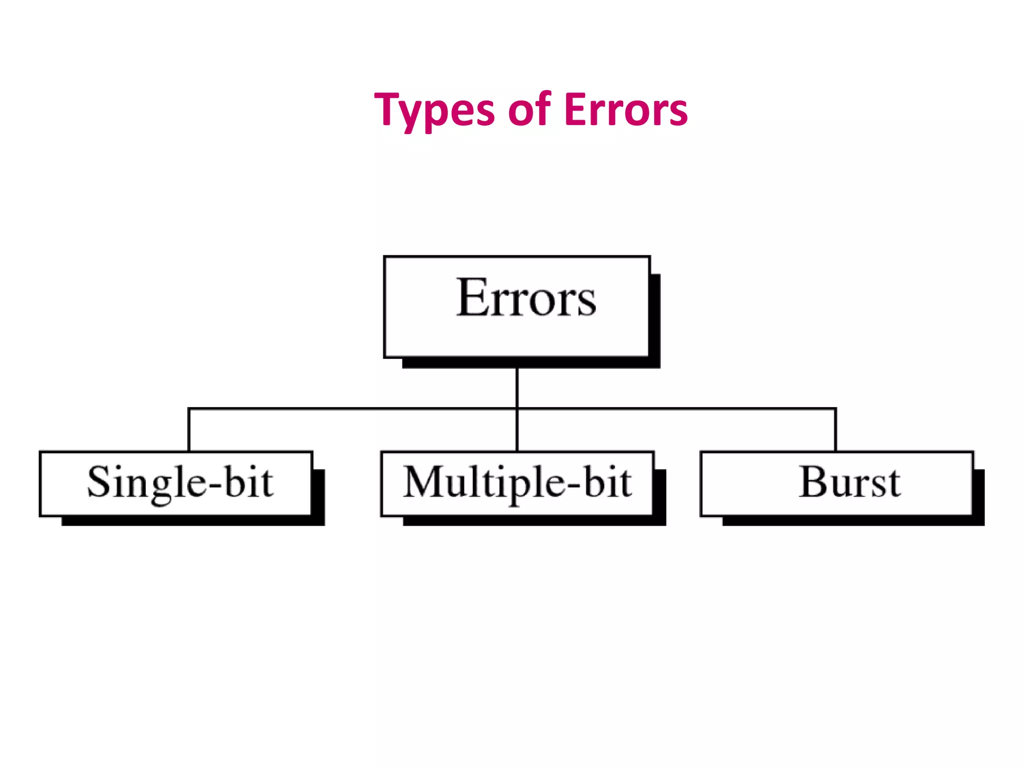
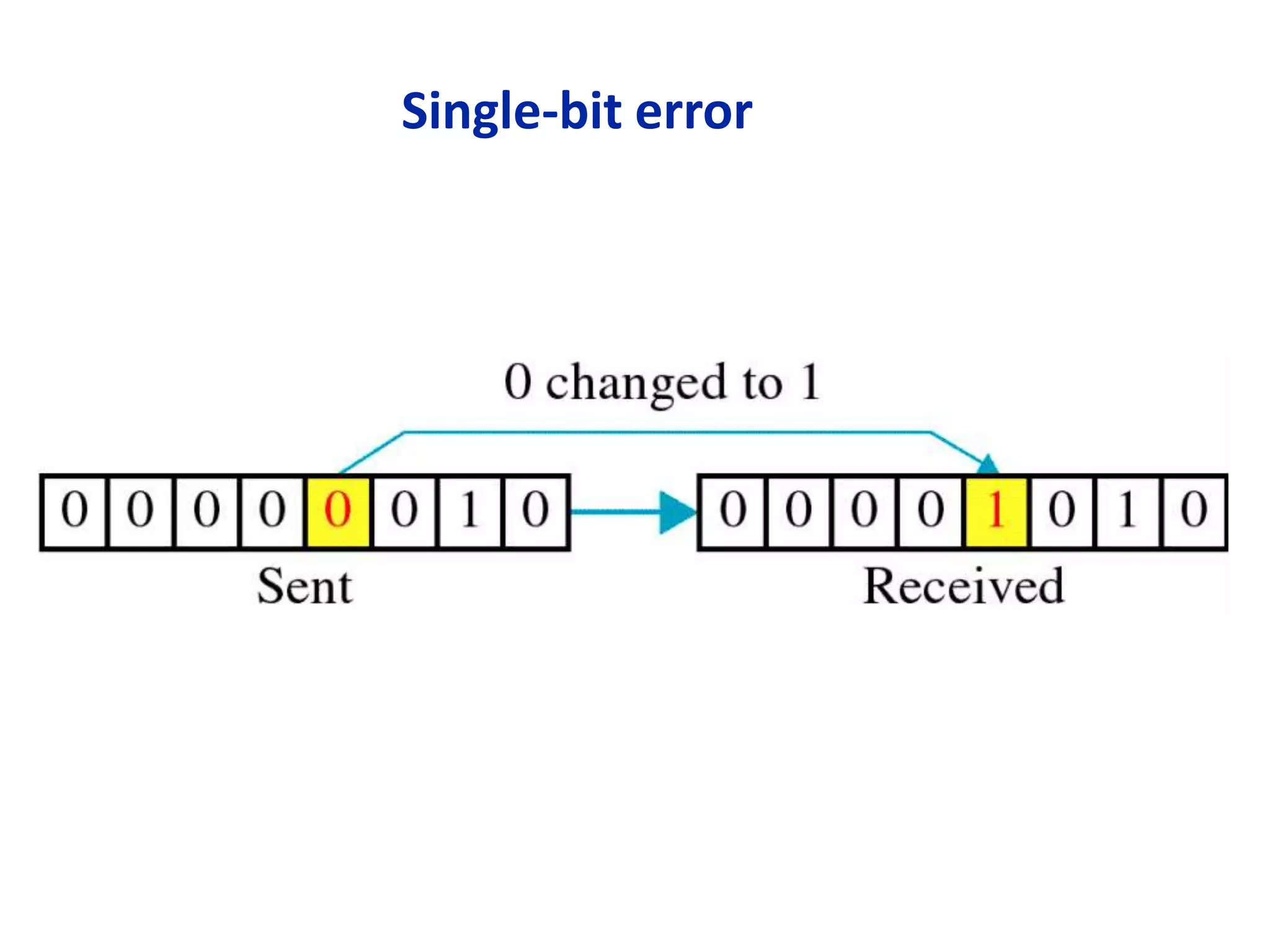
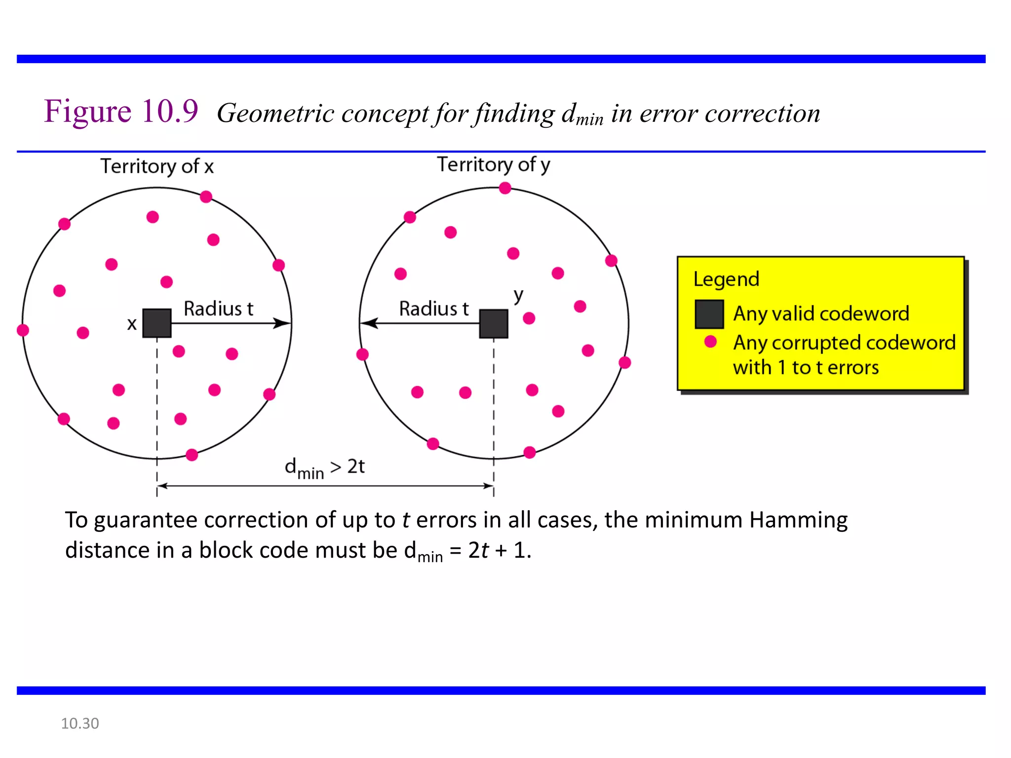
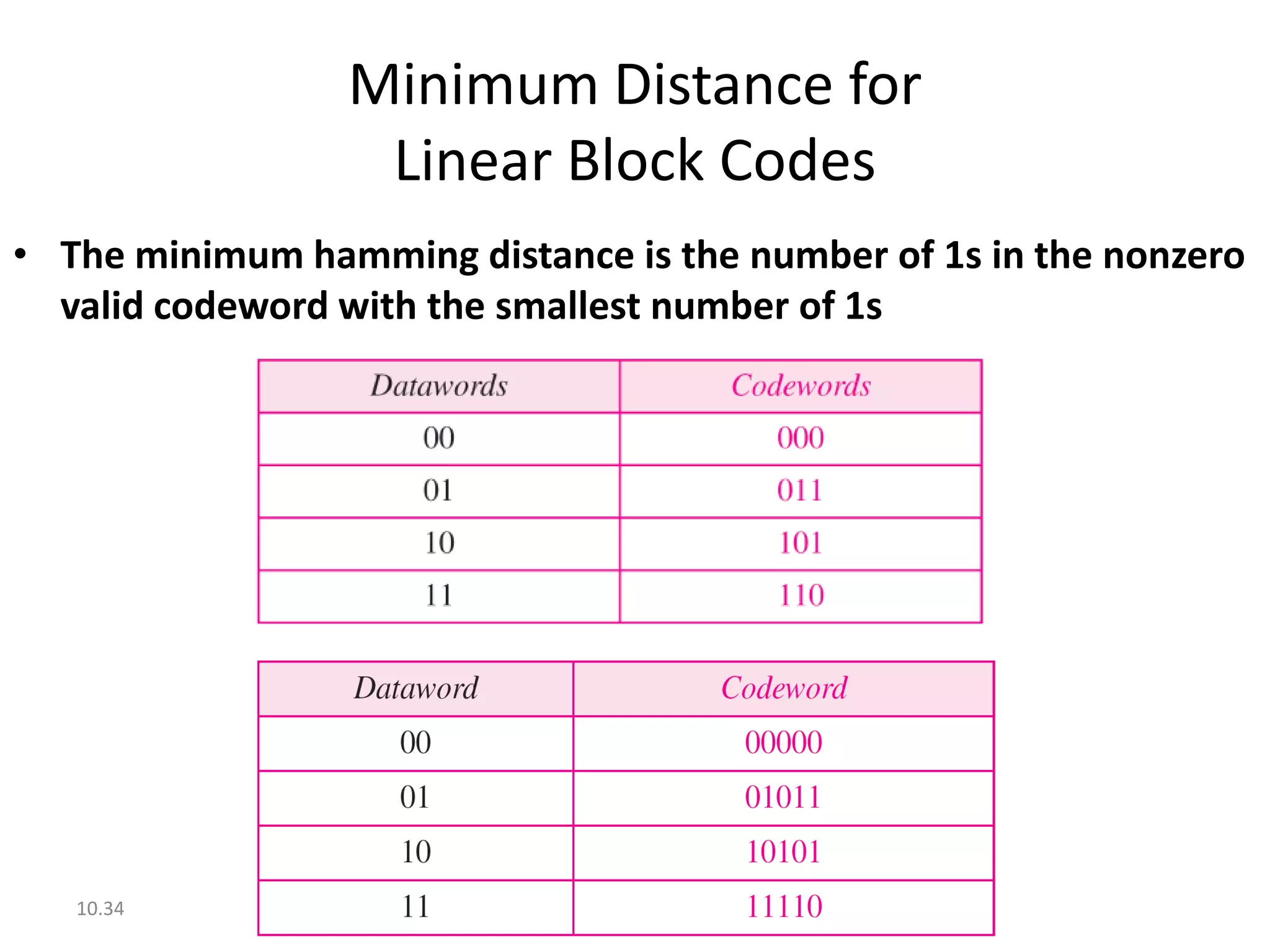
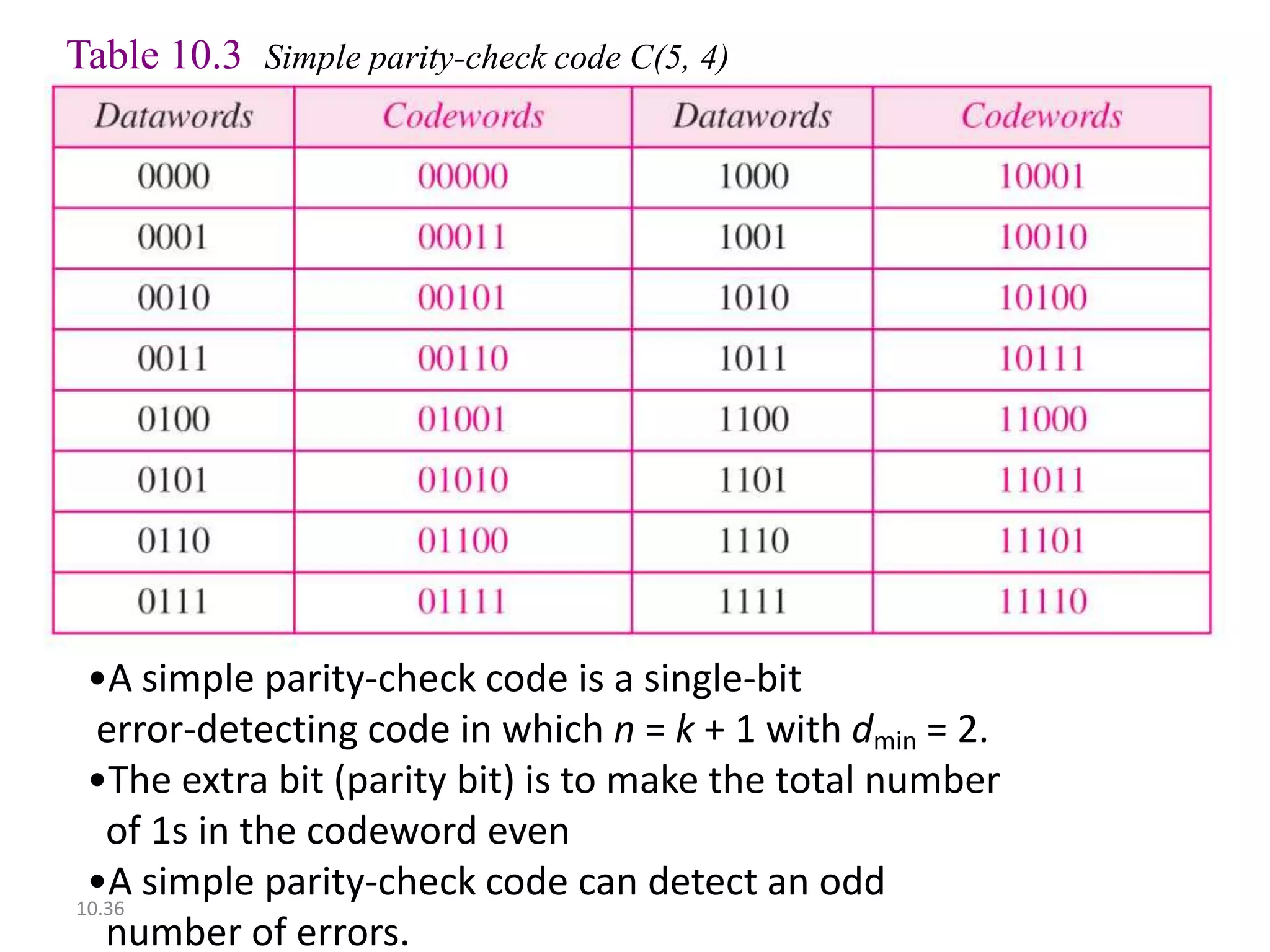
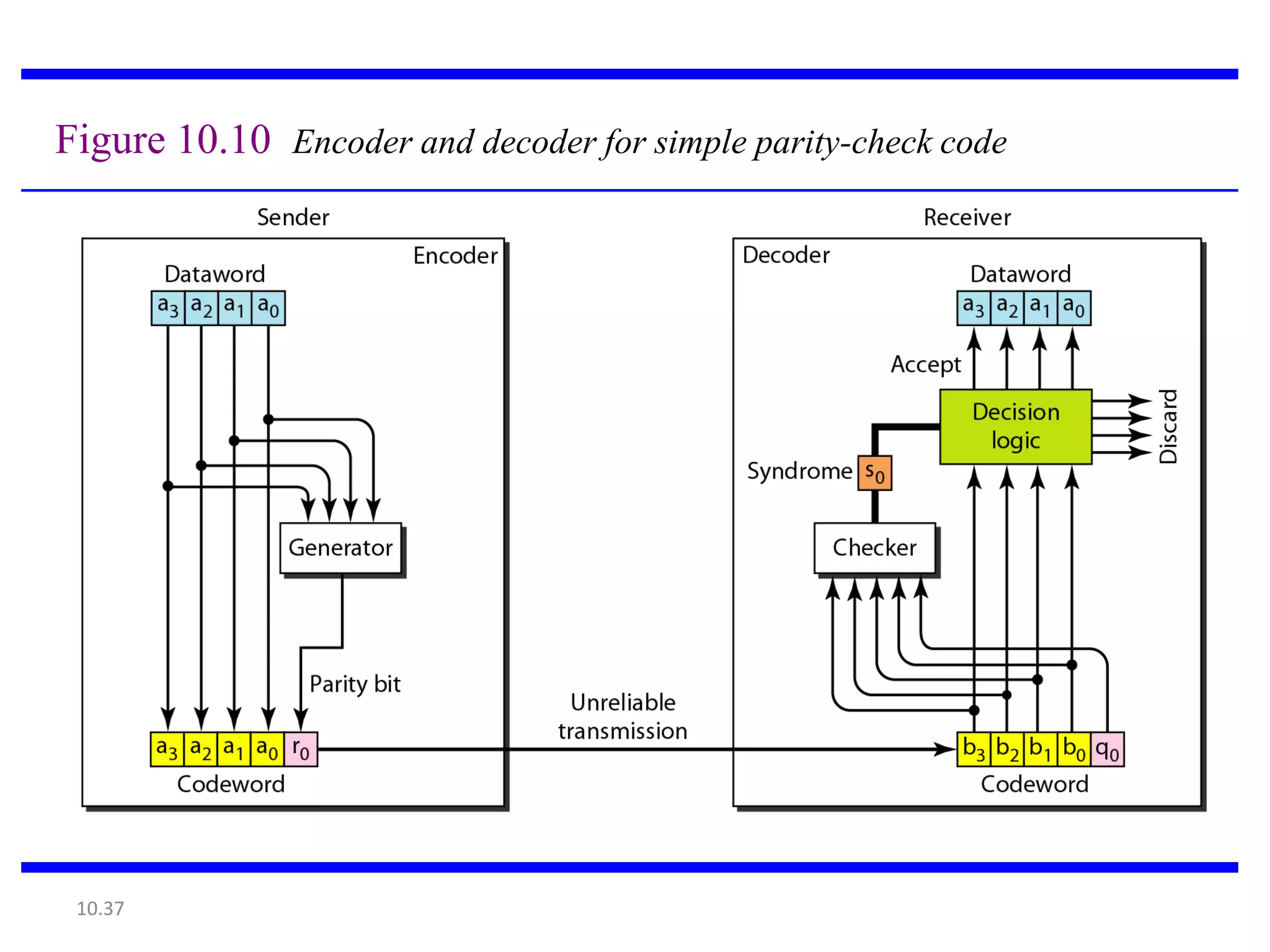
Chapter 10
           Error Detection
           and Correction

• Types of Errors
• Detection
• Correction
Basic concepts
 Networks must be able to transfer data from
 one device to another with complete accuracy.
 Data can be corrupted during transmission.
 For reliable communication, errors must be
 detected and corrected.
 Error detection and correction
 are implemented either at the data link
 layer or the transport layer of the OSI
 model.
Types of Errors
Single-bit error
Single bit errors are the least likely type of
  errors in serial data transmission because
  the noise must have a very short duration
  which is very rare. However this kind of
  errors can happen in parallel transmission.
Example:
If data is sent at 1Mbps then each bit lasts
  only 1/1,000,000 sec. or 1 μs.
For a single-bit error to occur, the noise
  must have a duration of only 1 μs, which is
  very rare.
Burst error
The term burst error means that two or
more bits in the data unit have changed
from 1 to 0 or from 0 to 1.

Burst errors does not necessarily mean that
the errors occur in consecutive bits, the
length of the burst is measured from the
first corrupted bit to the last corrupted bit.
Some bits in between may not have been
corrupted.
Burst error is most likely to happen in serial
  transmission since the duration of noise is
  normally longer than the duration of a bit.
The number of bits affected depends on the
  data rate and duration of noise.
Example:
If data is sent at rate = 1Kbps then a noise of 1/100 sec
 can affect 10 bits.(1/100*1000)

If same data is sent at rate = 1Mbps then a noise of
 1/100 sec can affect 10,000 bits.(1/100*106)
Error detection

Error detection means to decide whether the
received data is correct or not without having a
copy of the original message.

Error detection uses the concept of
redundancy, which means adding extra bits for
detecting errors at the destination.
Error detection/correction
• Error detection
        – Check if any error has occurred
        – Don’t care the number of errors
        – Don’t care the positions of errors
• Error correction
        – Need to know the number of errors
        – Need to know the positions of errors
        – More difficult


10.11
Figure 10.3 The structure of encoder and decoder


         To detect or correct errors, we need to send extra (redundant) bits with data.


 10.12
Modular Arithmetic

• Modulus N: the upper limit
• In modulo-N arithmetic, we use only the
  integers in the range 0 to N −1, inclusive.
• If N is 2, we use only 0 and 1
• No carry in the calculation (sum and
  subtraction)


10.13
Figure 10.4 XORing of two single bits or two words


 10.14
BLOCK CODING
• Message is divided into blocks each of k bits
  called datawords.
• Adding r redundant bits to each block to make
  the length
•            n=k+r ; n=codeword
• Combination of datawords = 2^k
• Combination of codewords =2^n where n>k
• Block coding is one to one process
2^n -2^k codewords are not used.
Figure 10.5 Datawords and codewords in block coding


 10.17
Figure 10.6 Process of error detection in block coding


 10.18
A code for error detection


10.19
Structure of encoder and decoder in error correction


 10.20
Table 10.2 A code for error correction (Example 10.3)


10.21
Hamming Distance

• The Hamming distance between two words is
  the number of differences between
  corresponding bits.
• The minimum Hamming distance is the
  smallest Hamming distance between
   all possible pairs in a set of words.


10.22
We can count the number of 1s in the Xoring of two words

1. The Hamming distance d(000, 011) is 2 because


2. The Hamming distance d(10101, 11110) is 3 because


 10.23
Find the minimum Hamming distance of the coding scheme


Solution
We first find all Hamming distances.


The dmin in this case is 2.
10.24
Find the minimum Hamming distance of the coding scheme


Solution
We first find all the Hamming distances.


 The dmin in this case is 3.
 10.25
Minimum Distance for
               Error Detection
• To guarantee the detection of up to s errors in
  all cases, the minimum Hamming distance in a
  block code must be dmin = s + 1.


10.26
Example 10.7


•The minimum Hamming distance for our first code
scheme (Table 10.1) is 2. This code guarantees detection of
only a single error.
•For example, if the third codeword (101) is sent and one
error occurs, the received codeword does not match any
valid codeword. If two errors occur, however, the received
codeword may match a valid codeword and the errors are
not detected.
 10.27
Example 10.8


•Table 10.2 has dmin = 3. This code can detect up to two
errors. When any of the valid codewords is sent, two errors
create a codeword which is not in the table of valid
codewords.


 10.28
Figure 10.8 Geometric concept for finding dmin in error detection


 10.29
Figure 10.9 Geometric concept for finding dmin in error correction


 To guarantee correction of up to t errors in all cases, the minimum Hamming
 distance in a block code must be dmin = 2t + 1.


 10.30
Example 10.9


A code scheme has a Hamming distance dmin = 4. What is
the error detection and correction capability of this
scheme?


Solution
This code guarantees the detection of up to three
                        errors
(s = 3), but it can correct up to one error. In other
                       words,
if this code is used for error correction, part of its
capability is wasted. Error correction codes need to
have an odd minimum distance (3, 5, 7, . . . ).
   10.31
10-3 LINEAR BLOCK CODES


•Almost all block codes used today belong to a
subset called linear block codes.
•A linear block code is a code in which the
exclusive OR (addition modulo-2 / XOR) of two
valid codewords creates another valid
codeword.


 10.32
Example 10.10


Let us see if the two codes we defined in Table 10.1 and
Table 10.2 belong to the class of linear block codes.

1. The scheme in Table 10.1 is a linear block code
   because the result of XORing any codeword with any
   other codeword is a valid codeword. For example, the
   XORing of the second and third codewords creates the
   fourth one.

2. The scheme in Table 10.2 is also a linear block code.
   We can create all four codewords by XORing two
   other codewords.
 10.33
Minimum Distance for
                  Linear Block Codes
• The minimum hamming distance is the number of 1s in the nonzero
  valid codeword with the smallest number of 1s


   10.34
Linear Block Codes

• Simple parity-check code
• Hamming codes


10.35
Table 10.3 Simple parity-check code C(5, 4)


 •A simple parity-check code is a single-bit
  error-detecting code in which n = k + 1 with dmin = 2.
 •The extra bit (parity bit) is to make the total number
   of 1s in the codeword even
 •A simple parity-check code can detect an odd
10.36
   number of errors.
Figure 10.10 Encoder and decoder for simple parity-check code


 10.37
Encoder uses a generator that takes 4 bit dataword(a0 a1 a2 a3)
and generates a parity bit r0.
So a 5 bit code is generated.
Parity bit is added to make the number of 1s in the codeword
even.
                   r0=a3+a2+a1+a0 (modulo-2)
At the receiver, addition is done all over 5 bits.
The result is called syndrome.
It is one bit.
Syndrome is 0→ number of 1s is even
Syndrome is 1→ number of 1s is odd
                 S0=b3+b2+b1+b0+q0 (modulo-2)
Example 10.12


Let us look at some transmission scenarios. Assume the
sender sends the dataword 1011. The codeword created
from this dataword is 10111, which is sent to the receiver.
We examine five cases:

1. No error occurs; the received codeword is 10111. The
    syndrome is 0. The dataword 1011 is created.
2. One single-bit error changes a1 . The received
   codeword is 10011. The syndrome is 1. No dataword
   is created.
3. One single-bit error changes r0 . The received codeword
   is 10110. The syndrome is 1. No dataword is created.
 10.39
Example 10.12 (continued)


4. An error changes r0 and a second error changes a3 .
   The received codeword is 00110. The syndrome is 0.
   The dataword 0011 is created at the receiver. Note that
   here the dataword is wrongly created due to the
   syndrome value.
5. Three bits—a3, a2, and a1—are changed by errors.
   The received codeword is 01011. The syndrome is 1.
   The dataword is not created. This shows that the simple
   parity check, guaranteed to detect one single error, can
   also find any odd number of errors.


 10.40
Figure 10.11 Two-dimensional parity-check code


         Two-D parity check can detect upto 3 errors.

 10.41
Figure 10.11 Two-dimensional parity-check code


 10.42
HAMMING CODES
10-4 CYCLIC CODES


Cyclic codes are special linear block codes with one
extra property. In a cyclic code, if a codeword is
cyclically shifted (rotated), the result is another
codeword.

 For eg- if 1011000 is a codeword and if it is left shifted then
 0110001 is also a codeword.


 10.44
Table 10.6 A CRC code with C(7, 4)


10.45
Figure 10.14 CRC encoder and decoder


 10.46
In the encoder, the dataword has k bits.
Codeword has n bits.
Size of dataword is augmented by adding n-k 0s to the right
hand side of the word.
Size of divisor is n-k+1; predefined and agreed upon.
Generator divides the augmented dataword by the
divisor(modulo-2 division).
Quotient is discarded and the remainder(r2r1r0) is appended
to the dataword to create the codeword.
Decoder receives the codeword and a copy of all n bits is fed
to the checker which is a replica of the generator.
The remainder produced by the checker is a syndrome of n-k
bits which is fed to decision logic analyzer.
Syndrome bits→all 0s (no error) else discarded.
POLYNOMIALS

A pattern of 0 and 1 can be represented as a polynomial
with coefficients of 0 and 1.

The power of each term shows position of the bit.

Coefficient shows the value of the bit.

Degree of polynomial is highest power in it.

NOTE-Degree is one less than the number of bits in the
pattern.
Figure 10.21 A polynomial to represent a binary word


 10.49

Chapter 10

  • 1.
    Chapter 10 Error Detection and Correction • Types of Errors • Detection • Correction
  • 2.
    Basic concepts  Networksmust be able to transfer data from one device to another with complete accuracy.  Data can be corrupted during transmission.  For reliable communication, errors must be detected and corrected.  Error detection and correction are implemented either at the data link layer or the transport layer of the OSI model.
  • 3.
  • 4.
  • 5.
    Single bit errorsare the least likely type of errors in serial data transmission because the noise must have a very short duration which is very rare. However this kind of errors can happen in parallel transmission. Example: If data is sent at 1Mbps then each bit lasts only 1/1,000,000 sec. or 1 μs. For a single-bit error to occur, the noise must have a duration of only 1 μs, which is very rare.
  • 6.
  • 8.
    The term bursterror means that two or more bits in the data unit have changed from 1 to 0 or from 0 to 1. Burst errors does not necessarily mean that the errors occur in consecutive bits, the length of the burst is measured from the first corrupted bit to the last corrupted bit. Some bits in between may not have been corrupted.
  • 9.
    Burst error ismost likely to happen in serial transmission since the duration of noise is normally longer than the duration of a bit. The number of bits affected depends on the data rate and duration of noise. Example: If data is sent at rate = 1Kbps then a noise of 1/100 sec can affect 10 bits.(1/100*1000) If same data is sent at rate = 1Mbps then a noise of 1/100 sec can affect 10,000 bits.(1/100*106)
  • 10.
    Error detection Error detectionmeans to decide whether the received data is correct or not without having a copy of the original message. Error detection uses the concept of redundancy, which means adding extra bits for detecting errors at the destination.
  • 11.
    Error detection/correction • Errordetection – Check if any error has occurred – Don’t care the number of errors – Don’t care the positions of errors • Error correction – Need to know the number of errors – Need to know the positions of errors – More difficult 10.11
  • 12.
    Figure 10.3 Thestructure of encoder and decoder To detect or correct errors, we need to send extra (redundant) bits with data. 10.12
  • 13.
    Modular Arithmetic • ModulusN: the upper limit • In modulo-N arithmetic, we use only the integers in the range 0 to N −1, inclusive. • If N is 2, we use only 0 and 1 • No carry in the calculation (sum and subtraction) 10.13
  • 14.
    Figure 10.4 XORingof two single bits or two words 10.14
  • 15.
    BLOCK CODING • Messageis divided into blocks each of k bits called datawords. • Adding r redundant bits to each block to make the length • n=k+r ; n=codeword • Combination of datawords = 2^k • Combination of codewords =2^n where n>k • Block coding is one to one process
  • 16.
    2^n -2^k codewordsare not used.
  • 17.
    Figure 10.5 Datawordsand codewords in block coding 10.17
  • 18.
    Figure 10.6 Processof error detection in block coding 10.18
  • 19.
    A code forerror detection 10.19
  • 20.
    Structure of encoderand decoder in error correction 10.20
  • 21.
    Table 10.2 Acode for error correction (Example 10.3) 10.21
  • 22.
    Hamming Distance • TheHamming distance between two words is the number of differences between corresponding bits. • The minimum Hamming distance is the smallest Hamming distance between all possible pairs in a set of words. 10.22
  • 23.
    We can countthe number of 1s in the Xoring of two words 1. The Hamming distance d(000, 011) is 2 because 2. The Hamming distance d(10101, 11110) is 3 because 10.23
  • 24.
    Find the minimumHamming distance of the coding scheme Solution We first find all Hamming distances. The dmin in this case is 2. 10.24
  • 25.
    Find the minimumHamming distance of the coding scheme Solution We first find all the Hamming distances. The dmin in this case is 3. 10.25
  • 26.
    Minimum Distance for Error Detection • To guarantee the detection of up to s errors in all cases, the minimum Hamming distance in a block code must be dmin = s + 1. 10.26
  • 27.
    Example 10.7 •The minimumHamming distance for our first code scheme (Table 10.1) is 2. This code guarantees detection of only a single error. •For example, if the third codeword (101) is sent and one error occurs, the received codeword does not match any valid codeword. If two errors occur, however, the received codeword may match a valid codeword and the errors are not detected. 10.27
  • 28.
    Example 10.8 •Table 10.2has dmin = 3. This code can detect up to two errors. When any of the valid codewords is sent, two errors create a codeword which is not in the table of valid codewords. 10.28
  • 29.
    Figure 10.8 Geometricconcept for finding dmin in error detection 10.29
  • 30.
    Figure 10.9 Geometricconcept for finding dmin in error correction To guarantee correction of up to t errors in all cases, the minimum Hamming distance in a block code must be dmin = 2t + 1. 10.30
  • 31.
    Example 10.9 A codescheme has a Hamming distance dmin = 4. What is the error detection and correction capability of this scheme? Solution This code guarantees the detection of up to three errors (s = 3), but it can correct up to one error. In other words, if this code is used for error correction, part of its capability is wasted. Error correction codes need to have an odd minimum distance (3, 5, 7, . . . ). 10.31
  • 32.
    10-3 LINEAR BLOCKCODES •Almost all block codes used today belong to a subset called linear block codes. •A linear block code is a code in which the exclusive OR (addition modulo-2 / XOR) of two valid codewords creates another valid codeword. 10.32
  • 33.
    Example 10.10 Let ussee if the two codes we defined in Table 10.1 and Table 10.2 belong to the class of linear block codes. 1. The scheme in Table 10.1 is a linear block code because the result of XORing any codeword with any other codeword is a valid codeword. For example, the XORing of the second and third codewords creates the fourth one. 2. The scheme in Table 10.2 is also a linear block code. We can create all four codewords by XORing two other codewords. 10.33
  • 34.
    Minimum Distance for Linear Block Codes • The minimum hamming distance is the number of 1s in the nonzero valid codeword with the smallest number of 1s 10.34
  • 35.
    Linear Block Codes •Simple parity-check code • Hamming codes 10.35
  • 36.
    Table 10.3 Simpleparity-check code C(5, 4) •A simple parity-check code is a single-bit error-detecting code in which n = k + 1 with dmin = 2. •The extra bit (parity bit) is to make the total number of 1s in the codeword even •A simple parity-check code can detect an odd 10.36 number of errors.
  • 37.
    Figure 10.10 Encoderand decoder for simple parity-check code 10.37
  • 38.
    Encoder uses agenerator that takes 4 bit dataword(a0 a1 a2 a3) and generates a parity bit r0. So a 5 bit code is generated. Parity bit is added to make the number of 1s in the codeword even. r0=a3+a2+a1+a0 (modulo-2) At the receiver, addition is done all over 5 bits. The result is called syndrome. It is one bit. Syndrome is 0→ number of 1s is even Syndrome is 1→ number of 1s is odd S0=b3+b2+b1+b0+q0 (modulo-2)
  • 39.
    Example 10.12 Let uslook at some transmission scenarios. Assume the sender sends the dataword 1011. The codeword created from this dataword is 10111, which is sent to the receiver. We examine five cases: 1. No error occurs; the received codeword is 10111. The syndrome is 0. The dataword 1011 is created. 2. One single-bit error changes a1 . The received codeword is 10011. The syndrome is 1. No dataword is created. 3. One single-bit error changes r0 . The received codeword is 10110. The syndrome is 1. No dataword is created. 10.39
  • 40.
    Example 10.12 (continued) 4.An error changes r0 and a second error changes a3 . The received codeword is 00110. The syndrome is 0. The dataword 0011 is created at the receiver. Note that here the dataword is wrongly created due to the syndrome value. 5. Three bits—a3, a2, and a1—are changed by errors. The received codeword is 01011. The syndrome is 1. The dataword is not created. This shows that the simple parity check, guaranteed to detect one single error, can also find any odd number of errors. 10.40
  • 41.
    Figure 10.11 Two-dimensionalparity-check code Two-D parity check can detect upto 3 errors. 10.41
  • 42.
    Figure 10.11 Two-dimensionalparity-check code 10.42
  • 43.
  • 44.
    10-4 CYCLIC CODES Cycliccodes are special linear block codes with one extra property. In a cyclic code, if a codeword is cyclically shifted (rotated), the result is another codeword. For eg- if 1011000 is a codeword and if it is left shifted then 0110001 is also a codeword. 10.44
  • 45.
    Table 10.6 ACRC code with C(7, 4) 10.45
  • 46.
    Figure 10.14 CRCencoder and decoder 10.46
  • 47.
    In the encoder,the dataword has k bits. Codeword has n bits. Size of dataword is augmented by adding n-k 0s to the right hand side of the word. Size of divisor is n-k+1; predefined and agreed upon. Generator divides the augmented dataword by the divisor(modulo-2 division). Quotient is discarded and the remainder(r2r1r0) is appended to the dataword to create the codeword. Decoder receives the codeword and a copy of all n bits is fed to the checker which is a replica of the generator. The remainder produced by the checker is a syndrome of n-k bits which is fed to decision logic analyzer. Syndrome bits→all 0s (no error) else discarded.
  • 48.
    POLYNOMIALS A pattern of0 and 1 can be represented as a polynomial with coefficients of 0 and 1. The power of each term shows position of the bit. Coefficient shows the value of the bit. Degree of polynomial is highest power in it. NOTE-Degree is one less than the number of bits in the pattern.
  • 49.
    Figure 10.21 Apolynomial to represent a binary word 10.49