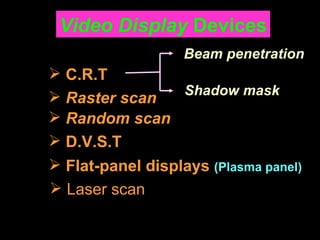
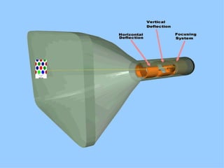
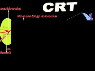
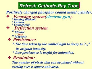
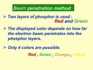
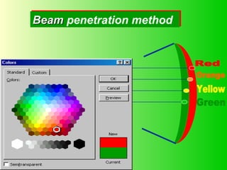
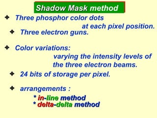
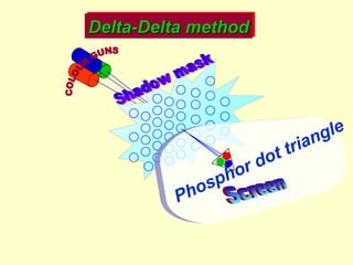
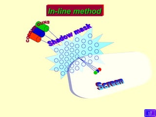
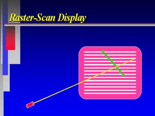
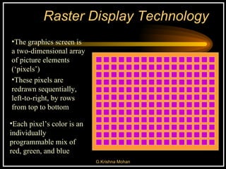
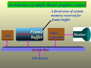
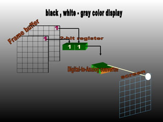
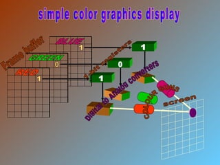
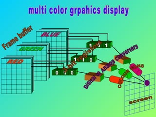
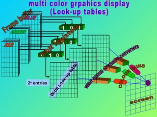
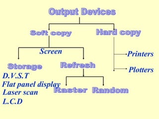
Chapter-2 Overview of Graphics Systems
Video Display  Devices Raster scan Random scan D.V.S.T Laser scan Flat-panel displays  (Plasma panel) C.R.T Beam   penetration Shadow mask
 
electron gun phosphor coated screen heating filament cathode control grid focusing anode accelerating anode Horizontal deflection plates vertical deflection plates CRT
Refresh Cathode-Ray Tube * The time taken by the emitted light to decay to  1 / 10   th its original intensity.    Persistence: * Low persistence is useful for animation.  Resolution: The number of pixels that can be plotted without overlap over a square unit area. Positively charged phosphor coated metal cylinder. Focusing system( electron gun ). Deflection system. *  Electric *  Magnetic * Heating filament * Cathode * Control grid (or)
Beam  penetration method Two layers of phosphor is used : Red  and  Green The displayed color depends on how far the electron beam penetrates into the phosphor layers. Only 4 colors are possible. Red  ,  Green  ,  Orange  ,  Yellow
Red Orange Green Yellow Beam  penetration method
  Three phosphor color dots  at each pixel position.   Three electron guns.   Color variations:   varying the intensity levels of  the three electron beams.   24 bits of storage per pixel.   arrangements : *  in - line  method *  delta - delta  method Shadow Mask  method
COLOUR GUNS Screen Shadow mask Delta-Delta method Phosphor dot triangle
COLOUR GUNS Screen Shadow mask In-line method
 
Raster Display Technology The graphics screen is a two-dimensional array of picture elements (‘pixels’) Each pixel’s color is an individually programmable mix of red, green, and blue These pixels are redrawn sequentially, left-to-right, by rows from top to bottom
Architecture of simple Raster graphics system CPU System Memory System Bus I/O devices Video  controller Monitor Frame  buffer A fixed area of system memory reserved for frame buffer
Raster Scan Memory Requirements  Interlacing * Even lines first * Odd lines next * 50 Hz to avoid flicker Memory Requirements depends on  * resolution  * colors,  the system supports ex: For a resolution of  1024 * 768  Resolution with  8-bits  per pixel( 256 colors ), it needs  768 Kb  of memory.
Raster-Scan display processor CPU System Memory System Bus I/O devices Display  processor memory Frame  Buffer Video controller Display processor  Monitor
Raster Scan Display processor  Display processor /  Graphics controller  To free the cpu from graphics chores Scan conversion :Digitize a picture definition into  a set of pixel intensity values.  Display processor functions. * Generating various line styles. * Displaying color areas. * Performs certain transformations. * Manipulations on display objects.    Run-length encoding.  * Reduce memory requirements. * Organize the frame buffer as a linked list. * Stores a scan line as a set of integer pairs. ( Intensity , number of adjacent pixels with that intensity ).
Raster Scan Generator X Register Y Register Memory Address Frame Buffer Pixel Register Horizontal and  vertical deflection voltages Intensity Video controller addr (x,y) =  base address + (x max  – x min )(y – y min ) + ( x – x min )
Video controller    Co- ordinate  system    Frame buffer locations are  referenced in Cartesian co-ordinates.    Co-ordinate origin * Lower left screen corner. * Upper left screen corner.    Refresh operations of video controller    Top-to-bottom , Left-to-Right    X register(initial value = 0).    Y register (initial value = y max  )
scan line Horizontal retrace Vertical retrace RASTER SCAN
Frame Buffers Rotating Memory Shift Register Multiple Plane
1 1-bit register black and white display 1 Digital-to-Analog converter Frame buffer screen
2-bit register black , white - gray color display Digital-to-Analog converter Frame buffer screen 1 1 1 1
Frame buffer Digital to Analog converters 1-bit registers simple color graphics display COLOUR GUNS screen 1 0 1 1 1 0 RED GREEN BLUE
Frame buffer screen multi color grpahics display 3-bit registers COLOUR GUNS Digital to Analog converters RED GREEN BLUE 1 0 0 0 1 1 1 1 0
Frame buffer screen multi color grpahics display (Look-up tables) 3-bit registers COLOUR GUNS W-bit Digital to Analog converters W-bit Look-up table 2 n  entries RED GREEN BLUE 1 0 1 0 1 1 0 1 0
Frame Buffer / Refresh Buffer Scan conversion Pixel  or  pel Scan line bitmap , pixmap Refreshing (60-80 frames/sec) Horizontal retrace vertical retrace Interlacing Flickering Aspect Ratio Stair step / jig-jag effect
 
Random scan system CPU System Memory System Bus I/O devices Display processor  Monitor Graphics commands are translated into a display  file stored in the system memory.
RANDOM SCAN
Random-Scan display  Vector  /  Stroke-Writing  /  Calligraphic .  Picture definition is stored as a set of line  drawing commands called  display file .  Draw a picture one line at a time.  Refresh rate depends on the number of  lines to be displayed.  Designed for line drawing applications.  Electron beam directly draws the picture.
+ very high resolution. + Easy animation. + Little memory requirements. -  Can’t draw a complex image (flicker) . -  Limited colour capability. -  Very expensive.
flood gun writing gun writing beam electrons screen storage grid collector DVST
Direct-View storage tube    Store the picture information inside the CRT as a charge distribution just behind the phosphor coated screen.  There exist two electron guns.  Primary gun.  Flood gun. + Very complex pictures can be displayed at very high resolutions. - Do not display color. - Selected parts of the picture cannot be erased.
Flat-panel displays  Video devices have reduced  * volume * weight * Power requirements compared to CRT.  A significant feature is thinner than CRT.  Classified into 2 categories  Emissive displays.  Non Emissive displays.
Emissive displays  Convert electrical energy into light. Plasma panels. Thin-film electroluminescent displays light emitting diodes Non Emissive displays  Convert sunlight or other into graphic patterns. L iquid  C rystal  D isplays( LCD ). Calculators, portable,laptop  computers Produce a picture by passing polarized light from the surroundings or from an internal light source through liquid-crystal that can be aligned to either block or transmit the light.
Neon gas plasma panel
polarizer polarizer Transparent conductor Transparent conductor On State Nematic Liquid Crystal Liquid Crystal Display
polarizer polarizer Transparent conductor Transparent conductor Off State Nematic Liquid Crystal Liquid Crystal Display
Keyboard   Mouse   Joystick   Digitising Tablet  Touch Sensitive Screen  Light Pen  Space Mouse  Digital Stills Camera   Magnetic Ink CharacterRecognition (MICR)   Optical Mark Reader(OMR)   Image Scanner   Bar Codes  Magnetic Reader   Smart Cards   Voice Data Entry  Sound Capture  Video Capture


Output Devices Hard copy Printers Plotters Storage Refresh Raster Random Screen D.V.S.T Flat panel display Laser scan L.C.D Soft copy
Element  Dot matrix  Line  Inkjet Printers impact non impact Laser printers
Flat bed Drum Plotters
Co - ordinate   Representations Modeling Co-ordinates:  (X mc ,Y mc ,Z mc ) World Co-ordinates:  (X wc ,Y wc ,Z wc ) Normalized Co-ordinates:  (X nc ,Y nc ,Z nc ) Device Co-ordinates:  (X dc ,Y dc ,Z dc ) * Any floating point values * Any floating point values * Integers within the range (0,0) to (X max  , Y max ). * 0 <= X nc  <= 1,  0 <= Y nc  <= 1,  0 <= Z nc  <= 1.
Co-ordinate Representations 1 1 1 Modeling  co-ordinates World  co-ordinates Normalized co-ordinates
Graphics software standards GKS  :-   Graphics Kernel System PHIGS :-   Programmer’s Hierarchical  Interactive Graphics Standard
The End
laser modulator focusing lense x-y deflectors photochromic film light source screen stored picture beam refresh beam projection light LASER SCAN
Run-Length Encoding (RLE) A simple technique for ‘data-compression’ Well-suited for compressing images, when adjacent pixels often have the same colors Without compression, a computer graphics image-file (for SuperVGA) would be BIG! Exact size depends on screen-resolution Also depends on the display’s color-depth  (Those parameters are programmable)
How RLE-compression works If multiple consecutive bytes are identical: example: 0x29 0x29 0x29 0x29 0x29 (This is called a ‘run’ of five identical bytes) We “compress” five bytes into two bytes: the example compressed:  0xC5 0x29 Byte-pairs are used to describe ‘runs’:  Initial byte encodes a ‘repetition-count’ (The following byte is the actual data)
 

Cg Chap 02

  • 1.
    Chapter-2 Overview ofGraphics Systems
  • 2.
    Video Display Devices Raster scan Random scan D.V.S.T Laser scan Flat-panel displays (Plasma panel) C.R.T Beam penetration Shadow mask
  • 3.
  • 4.
    electron gun phosphorcoated screen heating filament cathode control grid focusing anode accelerating anode Horizontal deflection plates vertical deflection plates CRT
  • 5.
    Refresh Cathode-Ray Tube* The time taken by the emitted light to decay to 1 / 10 th its original intensity.  Persistence: * Low persistence is useful for animation.  Resolution: The number of pixels that can be plotted without overlap over a square unit area. Positively charged phosphor coated metal cylinder. Focusing system( electron gun ). Deflection system. * Electric * Magnetic * Heating filament * Cathode * Control grid (or)
  • 6.
    Beam penetrationmethod Two layers of phosphor is used : Red and Green The displayed color depends on how far the electron beam penetrates into the phosphor layers. Only 4 colors are possible. Red , Green , Orange , Yellow
  • 7.
    Red Orange GreenYellow Beam penetration method
  • 8.
      Threephosphor color dots at each pixel position.   Three electron guns.   Color variations: varying the intensity levels of the three electron beams.   24 bits of storage per pixel.   arrangements : * in - line method * delta - delta method Shadow Mask method
  • 9.
    COLOUR GUNS ScreenShadow mask Delta-Delta method Phosphor dot triangle
  • 10.
    COLOUR GUNS ScreenShadow mask In-line method
  • 11.
  • 12.
    Raster Display TechnologyThe graphics screen is a two-dimensional array of picture elements (‘pixels’) Each pixel’s color is an individually programmable mix of red, green, and blue These pixels are redrawn sequentially, left-to-right, by rows from top to bottom
  • 13.
    Architecture of simpleRaster graphics system CPU System Memory System Bus I/O devices Video controller Monitor Frame buffer A fixed area of system memory reserved for frame buffer
  • 14.
    Raster Scan MemoryRequirements  Interlacing * Even lines first * Odd lines next * 50 Hz to avoid flicker Memory Requirements depends on * resolution * colors, the system supports ex: For a resolution of 1024 * 768 Resolution with 8-bits per pixel( 256 colors ), it needs 768 Kb of memory.
  • 15.
    Raster-Scan display processorCPU System Memory System Bus I/O devices Display processor memory Frame Buffer Video controller Display processor Monitor
  • 16.
    Raster Scan Displayprocessor  Display processor / Graphics controller  To free the cpu from graphics chores Scan conversion :Digitize a picture definition into a set of pixel intensity values.  Display processor functions. * Generating various line styles. * Displaying color areas. * Performs certain transformations. * Manipulations on display objects.  Run-length encoding.  * Reduce memory requirements. * Organize the frame buffer as a linked list. * Stores a scan line as a set of integer pairs. ( Intensity , number of adjacent pixels with that intensity ).
  • 17.
    Raster Scan GeneratorX Register Y Register Memory Address Frame Buffer Pixel Register Horizontal and vertical deflection voltages Intensity Video controller addr (x,y) = base address + (x max – x min )(y – y min ) + ( x – x min )
  • 18.
    Video controller  Co- ordinate system  Frame buffer locations are referenced in Cartesian co-ordinates.  Co-ordinate origin * Lower left screen corner. * Upper left screen corner.  Refresh operations of video controller  Top-to-bottom , Left-to-Right  X register(initial value = 0).  Y register (initial value = y max )
  • 19.
    scan line Horizontalretrace Vertical retrace RASTER SCAN
  • 20.
    Frame Buffers RotatingMemory Shift Register Multiple Plane
  • 21.
    1 1-bit registerblack and white display 1 Digital-to-Analog converter Frame buffer screen
  • 22.
    2-bit register black, white - gray color display Digital-to-Analog converter Frame buffer screen 1 1 1 1
  • 23.
    Frame buffer Digitalto Analog converters 1-bit registers simple color graphics display COLOUR GUNS screen 1 0 1 1 1 0 RED GREEN BLUE
  • 24.
    Frame buffer screenmulti color grpahics display 3-bit registers COLOUR GUNS Digital to Analog converters RED GREEN BLUE 1 0 0 0 1 1 1 1 0
  • 25.
    Frame buffer screenmulti color grpahics display (Look-up tables) 3-bit registers COLOUR GUNS W-bit Digital to Analog converters W-bit Look-up table 2 n entries RED GREEN BLUE 1 0 1 0 1 1 0 1 0
  • 26.
    Frame Buffer /Refresh Buffer Scan conversion Pixel or pel Scan line bitmap , pixmap Refreshing (60-80 frames/sec) Horizontal retrace vertical retrace Interlacing Flickering Aspect Ratio Stair step / jig-jag effect
  • 27.
  • 28.
    Random scan systemCPU System Memory System Bus I/O devices Display processor Monitor Graphics commands are translated into a display file stored in the system memory.
  • 29.
  • 30.
    Random-Scan display Vector / Stroke-Writing / Calligraphic .  Picture definition is stored as a set of line drawing commands called display file .  Draw a picture one line at a time.  Refresh rate depends on the number of lines to be displayed.  Designed for line drawing applications.  Electron beam directly draws the picture.
  • 31.
    + very highresolution. + Easy animation. + Little memory requirements. - Can’t draw a complex image (flicker) . - Limited colour capability. - Very expensive.
  • 32.
    flood gun writinggun writing beam electrons screen storage grid collector DVST
  • 33.
    Direct-View storage tube Store the picture information inside the CRT as a charge distribution just behind the phosphor coated screen.  There exist two electron guns.  Primary gun.  Flood gun. + Very complex pictures can be displayed at very high resolutions. - Do not display color. - Selected parts of the picture cannot be erased.
  • 34.
    Flat-panel displays Video devices have reduced * volume * weight * Power requirements compared to CRT.  A significant feature is thinner than CRT.  Classified into 2 categories  Emissive displays.  Non Emissive displays.
  • 35.
    Emissive displays Convert electrical energy into light. Plasma panels. Thin-film electroluminescent displays light emitting diodes Non Emissive displays  Convert sunlight or other into graphic patterns. L iquid C rystal D isplays( LCD ). Calculators, portable,laptop computers Produce a picture by passing polarized light from the surroundings or from an internal light source through liquid-crystal that can be aligned to either block or transmit the light.
  • 36.
  • 37.
    polarizer polarizer Transparentconductor Transparent conductor On State Nematic Liquid Crystal Liquid Crystal Display
  • 38.
    polarizer polarizer Transparentconductor Transparent conductor Off State Nematic Liquid Crystal Liquid Crystal Display
  • 39.
    Keyboard Mouse Joystick Digitising Tablet Touch Sensitive Screen Light Pen Space Mouse Digital Stills Camera Magnetic Ink CharacterRecognition (MICR) Optical Mark Reader(OMR) Image Scanner Bar Codes Magnetic Reader Smart Cards Voice Data Entry Sound Capture Video Capture
  • 40.
  • 41.
  • 42.
  • 43.
  • 44.
  • 45.
  • 46.
  • 47.
  • 48.
  • 49.
  • 50.
  • 51.
  • 52.
  • 53.
  • 54.
    Output Devices Hardcopy Printers Plotters Storage Refresh Raster Random Screen D.V.S.T Flat panel display Laser scan L.C.D Soft copy
  • 55.
    Element Dotmatrix Line Inkjet Printers impact non impact Laser printers
  • 56.
    Flat bed DrumPlotters
  • 57.
    Co - ordinate Representations Modeling Co-ordinates: (X mc ,Y mc ,Z mc ) World Co-ordinates: (X wc ,Y wc ,Z wc ) Normalized Co-ordinates: (X nc ,Y nc ,Z nc ) Device Co-ordinates: (X dc ,Y dc ,Z dc ) * Any floating point values * Any floating point values * Integers within the range (0,0) to (X max , Y max ). * 0 <= X nc <= 1, 0 <= Y nc <= 1, 0 <= Z nc <= 1.
  • 58.
    Co-ordinate Representations 11 1 Modeling co-ordinates World co-ordinates Normalized co-ordinates
  • 59.
    Graphics software standardsGKS :- Graphics Kernel System PHIGS :- Programmer’s Hierarchical Interactive Graphics Standard
  • 60.
  • 61.
    laser modulator focusinglense x-y deflectors photochromic film light source screen stored picture beam refresh beam projection light LASER SCAN
  • 62.
    Run-Length Encoding (RLE)A simple technique for ‘data-compression’ Well-suited for compressing images, when adjacent pixels often have the same colors Without compression, a computer graphics image-file (for SuperVGA) would be BIG! Exact size depends on screen-resolution Also depends on the display’s color-depth (Those parameters are programmable)
  • 63.
    How RLE-compression worksIf multiple consecutive bytes are identical: example: 0x29 0x29 0x29 0x29 0x29 (This is called a ‘run’ of five identical bytes) We “compress” five bytes into two bytes: the example compressed: 0xC5 0x29 Byte-pairs are used to describe ‘runs’: Initial byte encodes a ‘repetition-count’ (The following byte is the actual data)
  • 64.