Download to read offline


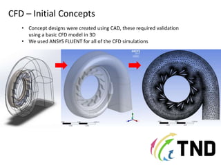
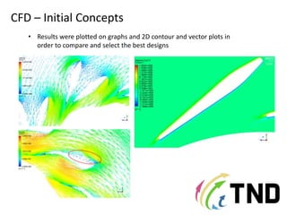
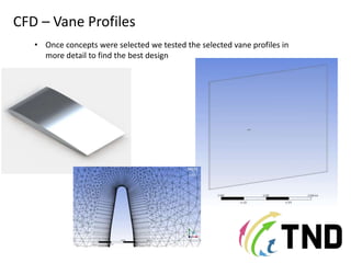
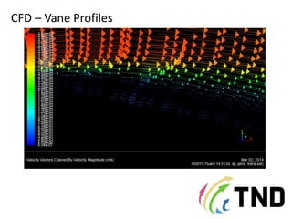
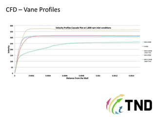
The document outlines the setup and results of a CFD turbocharger analysis, beginning with initial concept designs created in CAD and validated through basic 3D CFD modeling using ANSYS Fluent. Results included graphical representations for comparing and selecting the best designs. Further testing was conducted on selected vane profiles to optimize performance.


