FULL NIGHT — 9999894380 Call Girls In Jagat Puri | Delhi
Case 9010 excavator service repair manual
1. Cylinder Block
Cooling System
Batteries
IReprinted I
Description
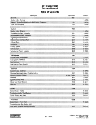
9010 Excavator
Service Manual
Table of Contents
Bur 7-45720
Section No. Form No.
2425 8-24183
2455 8-24203
4002 7-44950
Copyright 1993 Case Corporation
Printed in U.S.A.
Issued February 1993
2. Description
Hydraulic Swivel
Auxiliary Control Valve
Electric and Hydraulic Schematic Foldout
Bur 7-45720
9010 Excavator
Service Manual
Table of Contents
Section No. Form No.
8004 7-45880
8012 7-46770
In Rear Pocket 7-45710
Issued 2-93 Printed in U.S.A
5. 1001-3
TORQUE SPECIFICATIONS - METRIC HARDWARE
Use the following torques when specifications are
not given.
These values apply to fasteners with coarse threads
as received from supplier, plated or unplated, or when
lubricated with engine oil. These values do not apply if
graphite or molydisulfide grease or oil is used.
Grade 8.8 Bolts, Nuts, and Studs
ePound- Newton
Size Feet metres
M6 6-7 8-9
M8 14-17 20-23
M10 29-34 39-46
M12 50-59 68-80
M16 128-149 173-202
M20 249-291 337-393
M22 342-399 464-541
M24 431-503 584-681
M27 637-743 864-1008
M30 863-1007 1170-1365
M33 1180-1377 1600-1867
M36 1977-2307 2680-3127
M42 2434-2840 3300-3850
M45 3054-3563 4140-4830
M48 3658-4268 4960-5787
M52 4757-5549 6450-7525
M56 5908-6893 8010-9345
M64 8925-10413 12100-14117
Bur 7-44790
Grade 10.9 Bolts, Nuts, and Studs
€V
Pound- Newton
Size Feet metres
M6 8-10 11-13
M8 20-24 28-32
M10 41-47 55-64
M12 71-83 96-112
M16 178-208 242-282
M20 350-408 475-554
M22 481-561 652-761
M24 606-707 821-958
M27 900-1050 1220-1423
M30 1217-1420 1650-1925
M33 1667-1945 2260-2637
M36 2124-2478 2880-3360
M39 2773-3235 3760-4387
M42 3422-3992 4640-5413
M45 4293-5009 5820-6790
M48 5141-5998 6970-8132
M52 6690-7805 9070-10582
M56 8334-9723 11300-13183
M64 12612-14714 17100-19950
Grade 12.9 Bolts, Nuts, and Studs
€VUsually the torque values specified for grade 10.9
fasteners can be used satisfactorily on 'grade 12.9 fas-
teners.
Issued 11-92 Printed in U.S.A.
6. 1001-4
TORQUE SPECIFICATIONS - STEEL HYDRAULIC FITTINGS
Tube 00 Thread Pound- Newton
Hose 10 Size Feet metres
37 Degree Flare Fittings
1/4 in 7/16-20 6-12 8-16
6.4 mm
5/16 in 1/2-20 8-16 11-22
7.9 mm
3/8 in 9/16-18 10-25 14-34
9.5 mm
1/2 in 3/4-16 15-42 20-57
12.7 mm
5/8 in 7/8-14 25-58 34-79
15.9 mm
3/4 in 1-1/16-12 40-80 54-108
19.0 mm
7/8 in 1-3/16-12 60-100 81-135
22.2 mm
1.0 in 1-5/16-12 75-117 102-158
25.4 mm
1-1/4 in 1-5/8-12 125-165 169-223
31.8 mm
1-1/2 in 1-7/8-12 210-250 285-338
38.1 mm
Split Flange Mounting Bolts*
Pound- Newton
Size Feet metres
5/16-18 15-20 20-27
3/8-16 20-25 27-34
7/16-14 35-45 47-61
1/2-13 55-65 74-88
5/8-11 140-150 190-203
Bur 8-44790
Tube 00 Thread Pound- Newton
Hose 10 Size Feet metres
Straight Threads with O-ring
1/4 in 7/16-20 12-19 16-26
6.4 mm
5/16 in 1/2-20 16-25 22-34
7.9 mm
3/8 in 9/16-18 25-40 34-54
9.5 mm
1/2 in 3/4-16 42-67 57-91
12.7 mm
5/8 in 7/8-14 58-92 79-124
15.9 mm
3/4 in 1-1/16-12 80-128 108-174
19.0 mm
7/8 in 1-3/16-12 100-160 136-216
22.2 mm
1.0 in 1-5/16-12 117-187 159-253
25.4 mm
1-1/4 in 1-5/8-12 165-264 224-357
31.8 mm
1-1/2 in 1-7/8-12 250-400 339-542
38.1 mm
*NOTE: Use standard metric hardware torque for
metric split flange mounting bolts.
Issued 11-92 Printed in U.S.A.
7. Section
2001
ENGINE REMOVAL AND INSTALLATION
Bur 7-46680
Copyright 1993 Case Corporation
Printed in U.S.A.
Issued February 1993
8. 2001-4
ENGINE
Removal
1. Park the machine on a hard level surface. Lower the tool
to the floor and stop the engine.
2. Open the access doors over the engine and on each side
of the engine compartment. Remove the access covers
from under the engine and the radiator.
.~, ...
3. Make sure that the engine is cool and remove the radiator
cap. Open the drain valve and drain the cooling system.
The cooling system holds 5 U.S. gallons (18.9 litres) of
coolant.
Bur 7-46680
4. Remove the access cover for the batteries and
disconnect the ground cable.
1. Ground Cable
5. Remove the muffler and the mounting bracket for the
muffler.
6. Disconnect the hose for the air cleaner from the
turbocharger.
7. Disconnect the top (3) and bottom (4) radiator hoses from
the radiator.
8. Disconnect the hose (2) for the coolant reservoir from the
radiator.
g. Remove the fan guard and the fan shroud from the
radiator.
10. Remove the cap screws and hardware that hold the fan
and the spacer to the engine.
11. Disconnect the fuel supply hose and the fuel return hose.
Install a plug in each hose.
1. Supply Hose 2. Return Hose
Issued 2-93 Printed in U.S.A
9. 2001-5
u
B924479J
1. Disconnect Hose for Air Cleaner Here
2. Hose for the Coolant Reservoir
6. Self-Locking Nut
7. Washer
3. Top Radiator Hose 8. Insulator
4. Bottom Radiator Hose
5. Engine Mounting Bracket
9. Tighten to 195 to 231 pound-feet (264 to 313 Nm)
10. Tighten to 71 to 83 pound-feet (96 to 112 Nm)
Bur 7-46680
Issued 2-93 Printed in U.S.A
10. 2001-6
12. Disconnect the throttle cable from the bellcrank at the
bracket on the engine. If the machine is equipped with
ether start, disconnect the tube from the fitting in the
intake manifold.
1. Disconnect Throttle
Cable Here
2. Tube for Ether Start
13. Put identification tags on the wiring harness, wires and
cables connected to the engine for correct assembly.
Disconnect the wiring harness, wires and cables from the
engine.
14. Disconnect the hoses for the heater from the engine.
Install a plug in each hose.
Bur 7-46680
15. Disconnect the ground strap from the engine.
16. Connect acceptable lifting equipment to the lifting eyes
on the engine. The weight of the engine is 772 pounds
(350 kg).
17. Connect a lifting sling to the hydraulic pump. The weight
of the hydraulic pump is 201 pounds (91 kg). Remove the
cap screws and hardened washers that hold the hydraulic
pump to the flywheel housing.
18. Separate the hydraulic pump from the flywheel housing
and disengage the splined shaft of the hydraulic pump
from the splined hub in the coupling. The coupling and
the drive plate will stay with the flywheel.
19. Remove the self-locking nuts (6), washers (7), insulators
(8), and bolts (9) that hold the engine mounting brackets
(5) to the frame.
20. Make sure that all hoses, tubes, cables, wires, and wiring
harnesses are out of the way.
21. Lift the engine and remove the engine from the machine.
Issued 2-93 Printed in U.S.A
11. 2001-7
r
4
IT
1. Disconnect Hose for Air Cleaner Here
2. Hose for the Coolant Reservoir
B924479J
6. Self-Locking Nut
7. Washer
3. Top Radiator Hose 8. Insulator
4. Bottom Radiator Hose
5. Engine Mounting Bracket
9. Tighten to 195 to 231 pound-feet (264 to 313 Nm)
10. Tighten to 71 to 83 pound-feet (96 to 112 Nm)
Bur 7-46680
Issued 2-93 Printed in U.S.A
12. 2001-8
Installation
Installation is the reverse sequence of removal.
1. Check the condition of the insulators for the engine
mounts. If the insulators are damaged, install new
insulators.
2. Use the CAS-1690 tool to rotate the flywheel and align
the splined hub in the coupling with the splined shaft of
the hydraulic pump.
3. Tighten the bolts that hold the engine mounting brackets
to the frame to the torque specifications shown on page
3.
4. Tighten the cap screws that hold the hydraulic pump to
the flywheel housing to the torque specifications shown
on page 3.
5. Tighten the cap screws that hold the fan and the spacer
to the engine to the torque specifications shown on page
3.
6. Do the following procedure to bleed the air from the
cooling system.
A. Close the drain valve on the radiator. Fill the
radiator with coolant and fill the coolant reservoir to
the fill neck. If new coolant is being installed, the
coolant must be 55% ethylene glycol and 45%
water.
B. Install and tighten the radiator cap.
Bur 7-46680
C. Install and tighten the cap for the coolant reservoir.
D. Close the shutoff valve for the heater at the top rear
of the engine.
1. Shutoff Valve
E. Start and run the engine at low idle for one minute.
F. Stop the engine. Fill the radiator with coolant again
and fill the coolant reservoir again.
G. Cover the outside of the radiator core (the side
away from the fan) with cardboard.
H. Start and run the engine at high idle. Look at the
water temperature gauge. When the water
temperature gauge indicates normal operating
temperature (4th or 5th amber bar illuminated),
open the shutoff valve for the heater.
I. Continue to run the engine until the last amber bar
illuminates, then remove the cardboard from the
radiator.
Issued 2-93 Printed in U.S.A
13. J. Reduce the engine speed to low idle. Continue to
run the engine at low idle for 30 seconds.
K. Stop the engine and let the coolant cool.
L. When the radiator feels COLD, remove the radiator
cap and the cap for the coolant reservoir.
Bur 7-46680
2001-9
M. Fill the radiator with coolant. Install and tighten the
radiator cap.
N. Fill the coolant reservoir with coolant to the FULL
mark. Install the cap for the coolant reservoir.
Issued 2-93 Printed in U.S.A
14. 2002-3
RADIATOR
Removal
1. Park the machine on a hard level surface. Lower the tool
to the floor and stop the engine.
2. Open the access doors over the engine and on the left
side of the engine compartment. Remove the access
cover from under the radiator.
Bur 7-46690
3. Make sure that the engine is cool and remove the radiator
cap. Open the drain valve and drain the cooling system.
The cooling system holds 5 U.S. gallons (18.9 litres) of
coolant.
4. Disconnect the top and bottom radiator hoses from the
radiator.
5. Disconnect the hose for the coolant reservoir from the
radiator.
6. Remove the fan guard and the fan shroud from the
radiator.
7. Remove the cap screws and hardware that hold the fan
and the spacer to the engine. Remove the fan and the
spacer.
8. Connect acceptable lifting equipment to the radiator. The
weight of the radiator is 117 pounds (53 kg).
9. Remove the hardware that holds the radiator to the
frame.
10. Remove the radiator from the machine.
Issued 2-93 Printed in U.S.A
15. 2002-4
Installation
Installation is the reverse sequence of removal.
1. If the foam baffles were removed from the radiator, install
new foam baffles.
2. Tighten the cap screws that hold the fan and the spacer
to the engine to the torque specifications shown on page
2.
3. Do the following procedure to bleed the air from the
cooling system.
A. Close the drain valve on the radiator. Fill the
radiator with coolant and fill the coolant reservoir to
the fill neck. If new coolant is being installed, the
coolant must be 55% ethylene glycol and 45%
water.
B. Install and tighten the radiator cap.
C. Install and tighten the cap for the coolant reservoir.
Bur 7-46690
D. Close the shutoff valve for the heater at the top rear
of the engine.
1. Shutoff Valve
E. Start and run the engine at low idle for one minute.
F. Stop the engine. Fill the radiator with coolant again
and fill the coolant reservoir again.
G. Cove the outside of the radiator core (the side away
from the fan) with cardboard.
H. Start and run the engine at high idle. Look at the
water temperature gauge. When the water
temperature gauge indicates normal operating
temperature (4th or 5th amber bar illuminated),
open the shutoff valve for the heater.
I. Continue to run the engine until the last amber bar
illuminates, then remove the cardboard from the
radiator.
J. Reduce the engine speed to low idle. Continue to
run the engine at low idle for 30 seconds.
K. Stop the engine and let the coolant cool.
L. When the radiator feels COLD, remove the radiator
cap and the cap for the coolant reservoir.
M. Fill the radiator with coolant. Install and tighten the
radiator cap.
N. Fill the coolant reservoir with coolant to the FULL
mark. Install the cap for the coolant reservoir.
Issued 2-93 Printed in U.S.A
16. o
o
Bur 7-46690
,
,
"
.... --::.----~--::..::::-..;:..- ,.....
,
..... .::;.. / /
1/ /'
/ /
,
" / /'
.... I I
, - -- / /
, )-:::.-- --../
..... ..... .... ~/ ..... ,.... ~
-------~..==='.:::~ '
,,,
"'"" ",
- - I
1. - - - "
".....= ==-=-===-= I
/
'"
/
/
/
I
I
I
I
I
I
--------
Front View of Oil Cooler and Radiator
1. Radiator Cap 3. Oil Cooler
2. Radiator and Frame 4. Fan Shroud
o
o
5. Fan Guard
2002-5
o
----0~===~~
Side View of Oil Cooler, Radiator, Frame,
Fan Shroud, and Fan Guard
B924474J
7. Drain Hose
6. Drain Valve
Issued 2-93 Printed in U.S.A
17. 2402-3
RUN-IN INSTRUCTIONS
Engine Lubrication
Fill the 4-390 engine crankcase with CC/SF, CD/SF, CE/SF or CF-4 service classification oil. Use the correct viscosity
rating for the ambient air temperature. Install new oil filters after the engine is rebuilt.
Fill the 4T390 and the 4TA 390 engine crankcase with CE/SF or CF-4 service classification oil. Use the correct viscosity
rating for the ambient air temperature. Install new oil filters after the engine is rebuilt.
Run-In Procedure for Rebuilt Engine
Step 1 Disconnect the wire to the electric shut-off on the injection pump so that the engine will not start. Crank the
engine for 30 seconds until there is oil pressure, then reconnect the wire.
Step 2 Remove the air from the cooling system at the temperature sending unit.
Step 3 Run the engine at 1000 RPM minimum load for 5 minutes and check for oil leaks.
Step 4 During the Run-In, continue to check the oil pressure, coolant level, and coolant temperature.
Run-In Procedure for Rebuilt Engines (with a Dynamometer)
The following procedure must be followed when using a PTO dynamometer to Run-In the engine. The dynamometer will
control the engine load at each speed and will remove stress on new parts during Run-In.
During the Run-In, continue to check the oil pressure, coolant level and coolant temperature.
STEP
1
2
3
TIME
5 Minutes
5 Minutes
5 Minutes
ENGINE SPEED
1000 RPM
1100 RPM
2200 RPM
DYNAMOMETER SCALE LOAD
50
1/2
Full
Run-In Procedure for Rebuilt Engines (without a Dynamometer)
STEP
1
2
3
TIME
5 Minutes
5 Minutes
5 Minutes
ENGINE SPEED
1000 RPM
1100 RPM
2200 RPM
Run-In Procedure (Agriculture Equipment)
LOAD
No Load
Light Load
Light Load
For the first 8 hours of field operation stay one gear lower than normal. For the next 12 hours DO NOT "lug" the engine.
Prevent "lugging" by moving the lever to a lower gear. The engine must not be "lugged" below the rated engine RPM
during early hours of life.
Run-In Procedure (Construction Equipment)
For the first 8 hours, operate the engine at full throttle maintaining a normal load. Avoid converter or hydraulic stall. The
engine must not be "lugged" below the Rated Engine RPM (Do not stall the engine more than 10 seconds).
Rae 8-24163 Revised 2-92 Printed in U.S.A.
18. 2402-4
IDENTIFICATION MARKS
Crankshaft
Letter N = Nitroc Hardened, crankshaft must be rehardened to a minimum hardness of 450 HV 0.2 rockwell any time
the crankshaft has been reconditioned.
Cylinder Block
Letter X = The cylinder block has been refaced and up to 0.25 mm has been removed. Use a thicker head gasket (two
notches).
Letter XX = The cylinder block has been refaced and up to 0.50 mm has been removed. Use a thicker head gasket
(three notches).
Cylinder Head
Letter G = Thermostat passage in cylinder did not need to be machined.
Letter M = Thermostat passage in cylinder head was machined.
Letter V = Valve seats have been machined.
Letter X = The cylinders in the cylinder block have been bored oversize. Use a head gasket with oversize cylinder holes
(one notch). This gasket is used for standard replacement, 0.5 mm oversize and 1.0 mm oversize bore.
LetterXX = The cylinder block has been refaced and up to 0.25 mm has been removed use a thicker head gasket (two
notches).
Letter XXX = The cylinder block has been refaced and up to 0.50 mm has been removed. Use a thicker head gasket
(three notches).
Numbers = RH rear corner of cylinder head indicates the amount of material removed from the cylinder head.
ENGINE SPECIFICATION DETAILS
Cylinder Block
Metric Value
Type.............................................................................................................................................................Non-Sleeved
Material ..............................................................................................................................................................Cast Iron
ID of Cylinder ................................................................................................................................102.00 to 102.04 mm
Maximum Service Limit ........................................................................................................................... 102.116 mm
Cylinder Out of Round (Maximum) .................................................................................................................0.038 mm
Cylinder Taper (Maximum)..............................................................................................................................0.076 mrn
0.5 mm Oversize Piston
Machine Cylinder Bore to ......................................................................................................102.40 to 102.44 mm
Hone to (Finished Diameter) .................................................................................................102.50 to 102.54 mm
1.00 mm Oversize Piston
Machine Cylinder Bore to ......................................................................................................102.90 to 102.94 mm
Hone to (Finished Diameter) .................................................................................................103.00 to 103.04 mm
Warpage {Maximum).......................................................................................................................................0.075 mm
Maximum Material RemovaL.............................................................................................................................0.50 mm
Rae 8-24163 Revised 2-92 Printed in U.S.A.
19. Thank you very much for
your reading. Please Click
Here. Then Get COMPLETE
MANUAL. NO WAITING
NOTE:
If there is no response to
click on the link above,
please download the PDF
document first and then
click on it.
20. 2402-5
Service Cylinder Sleeve
Type............................................................................................................................................. Dry, Can Be Replaced
Material ..............................................................................................................................................................Cast Iron
Machine Cylinder Block Bore to ...............................................................................................104.485 to 104.515 mm
Installation ......................................................................................................................................................... Press Fit
Machine Sleeve Bore to:
Standard Size Piston (Finished Diameter) ................................................................................102.00 to 102.04 mm
0.5 mm Oversize Piston
Machine Cylinder Bore to ......................................................................................................102.40 to 102.44 mm
Hone to (Finished Diameter) .................................................................................................102.50 to 102.54 mm
1.0 mm Oversize Piston
Machine Cylinder Bore to ......................................................................................................102.90 to 102.94 mm
Hone to (Finished Diameter) .................................................................................................103.00 to 103.04 mm
Piston
Type.............................................................................................................................................................Cam Ground
Material ....................................................................................................................................................Aluminum Alloy
00 at 12 mm From the Bottom, 90 Degrees Piston Pin
Standard Size Piston .............................................................................................................101.873 to 101.887 mm
Minimum Service Limit......................................................................................................................... 101.823 mm
0.5 mm Oversize Piston ........................................................................................................102.373 to 102.387 mm
Minimum Service limit......................................................................................................................... 101.323 mm
1.0 mm Oversize Piston ........................................................................................................102.873 to 102.887 mm
Minimum Service limit......................................................................................................................... 102.823 mm
10 of Piston Pin Bore.....................................................................................................................40.006 to 40.012 mm
Maximum Service limit ..............................................................................................................................40.025 mm
Width of 1st Ring Groove (Top) ........................................................................................................2.465 to 2.485 mm
Width of 2nd Ring Groove (Intermediate).........................................................................................2.425 to 2.445 mm
Width of 3rd Ring Groove (Oil Ring) ................................................................................................4.040 to 4.060 mm
Protrusion Above Cylinder Block (Maximum) ................................................................................................. 0.660 mm
Protrusion Above Cylinder Block (Minimum) .................................................................................................. 0.280 mm
Piston Pin
Type...................................................................................................................................................................Full Float
00 of Pin.......................................................................................................................................39.997 to 40.003 mm
Minimum Service limit ..............................................................................................................................39.990 mm
Rae 8-24163 Revised 2-92 Printed in U.S.A.
21. 2402-6
Piston Rings
No.1 Compression 4T-390 Engine .................................................................................Key Stone Type (Barrel Face)
End Gap in 102.02 10 .........................................................................................................................0.4 to 0.70 mm
No.1 Compression 4-390 Engine ................................................................................Rectangular Type (Barrel Face)
End Gap in 102.02 10 .......................................................................................................................0.25 to 0.55 mm
Maximum Service Limit............................................................................................................................ 0.806 mm
Side Clearance ..............................................................................................................................0.075 to 0.120 mm
Maximum Service Limit..............................................................................................................................0.15 mm
No. 2 Compression.....................................................................................................Rectangular Type (Tapper Face)
End Gap in 102.02 10 .......................................................................................................................0.25 to 0.55 mm
Maximum Service Limit.............................................................................................................................0.806 mm
Side Clearance ..............................................................................................................................0.075 to 0.120 mm
Maximum Service Limit.............................................................................................................................. 0.15 mm
NO.3 Oil Control Rings ...................................................................................................................................Two Piece
End Gap in 102.02 10 .......................................................................................................................0.25 to 0.55 mm
Maximum Service Limit............................................................................................................................0.806 mm
Side Clearance ............................................................................................................................................0.130 mm
Cylinder Head
Warpage (Maximum) ......................................................................................................................................... 0.20 mm
Maximum Material Removal .......................................................................................................................... 1.00 mm
Minimum Head Height ................................................................................................................................93.75 mm
Engines Manufactured in U.S.A.:
Prior to Engine Serial Number 45511034 .................................................................................Injector Nozzle 9 mm
Engine Serial Number 45511034 and After ..............................................................................Injector Nozzle 7 mm
Engines Manufactured in Darlington England:
Prior to Engine Serial Number 21092870 .................................................................................Injector Nozzle 9 mm
Engine Serial Number 21092870 and After ..............................................................................Injector Nozzle 7 mm
Engines Manufactured in Neuss Germany:
Prior to Engine Serial Number 52107489 .................................................................................Injector Nozzle 9 mm
Engine Serial Number 52107489 and After ..............................................................................Injector Nozzle 7 mm
Lifters
Material..................................................................................................................................................... Hardened Iron
00 of Lifter ................................................................................................................................15.961 to 15.977 mm
Minimum Service Limit...........................................................................................................................15.960 mm
Bore Diameter in Block .............................................................................................................16.000 to 16.030 mm
Maximum Service Limit.......................................................................................................................... 16.055 mm
Rae 8-24163 Revised 2-92 Printed in U.S.A.
22. 2402-7
Connecting Rod
Bushing ............................................................................................................................ Steel Backed Leaded Bronze
Bushing 10 Installed (Ream to Size) .............................................................................................40.053 to 40.067 mm
Maximum Service Limit .............................................................................................................................40.092 mm
Bearing Liners ..............................................................................................................................................Replaceable
Journal 10 Without Bearing Liners ................................................................................................72.987 to 73.013 mm
Bearing Oil Clearance .......................................................................................................................0.038 to 0.116 mm
Maximum Service Limit ...............................................................................................................................0.129 mm
Side Clearance..................................................................................................................................0.100 to 0.300 mm
Maximum Service Limit ...............................................................................................................................0.330 mm
Connecting Rod Bend (Maximum)
Without Bushing ..........................................................................................................................................0.200 mm
With Bushing ...............................................................................................................................................0.150 mm
Connecting Rod Twist (Maximum)
Without Bushing ..........................................................................................................................................0.500 mm
With Bushing ...............................................................................................................................................0.300 mm
Connecting Rod Bolt Maximum ..............................................................................................................................59.25
Rae 8-24163 Revised 2-92 Printed in U.S.A.
23. 2402-8
Crankshaft
Type.......................................................................................................................................Hardened Steel, Balanced
Main Bearing Liners .....................................................................................................................................Replaceable
End Clearance, Center Main Bearing Cap ...........................................................................................0.13 to 0.25 mm
Center Main Bearing Thrust Surface Thickness ...............................................................................................2.50 mm
Connecting Rod Journal
00, Standard ............................................................................................................................68.987 to 69.013 mm
Maximum Service Limit..........................................................................................................................68.962 mm
0.25 mm 00 Undersize, Grind to .............................................................................................68.737 to 68.763 mm
Maximum Service Limit..........................................................................................................................68.712 mm
0.50 mm 00 Undersize, Grind to .............................................................................................68.487 to 68.513 mm
Maximum Service Limit..........................................................................................................................68.462 mm
0.75 mm 00 Undersize, Grind to .............................................................................................68.237 to 68.263 mm
Maximum Service Limit..........................................................................................................................68.212 mm
1.00 mm 00 Undersize, Grind to .............................................................................................67.987 to 68.013 mm
Maximum Service Limit..........................................................................................................................67.962 mm
Connecting Rod Journal Maximum Taper......................................................................................................0.013 mm
Journals Out of Round Maximum...................................................................................................................0.050 mm
Undersize Main Bearing Liners For Service ...................................................................0.25, 0.50, 0.75 and 1.00 mm
Main Bearing Oil Clearance ..............................................................................................................0.041 to 0.119 mm
Maximum Service Limit ...............................................................................................................................0.140 mm
Main Bearing Journal
00, Standard ............................................................................................................................82.987 to 83.013 mm
Maximum Service Limit..........................................................................................................................82.962 mm
0.25 mm 00 Undersize, Grind to .............................................................................................82.737 to 82.763 mm
Maximum Service Limit..........................................................................................................................82.712 mm
0.50 mm OD Undersize, Grind to .............................................................................................82.487 to 82.513 mm
Maximum Service Limit..........................................................................................................................82.462 mm
0.75 mm OD Undersize, Grind to .............................................................................................82.237 to 82.263 mm
Maximum Service Limit..........................................................................................................................82.212 mm
1.00 mm 00 Undersize, Grind to .............................................................................................81.987 to 82.013 mm
Maximum Service Limit..........................................................................................................................81.962 mm
Main Bearing Journal Bore ID No Liners......................................................................................87.982 to 88.018 mm
Maximum Service Limit .............................................................................................................................88.031 mm
Main Journal Width:
1st, 2nd, 3rd, 5th .......................................................................................................................37.424 to 37.576 mm
4th ..............................................................................................................................................37.475 to 37.525 mm
Connect Rod Journals Width ........................................................................................................38.950 to 39.050 mm
Main Bearing Bolt Maximum Length ............................................................................................................ 119.25 mm
Rae 8-24163 Revised 2-92 Printed in U.S.A.
24. 2402-9
Camshaft
Type.......................................................................................................................................................... Hardened Iron
Bushing (Front Only) ............................................................................................................................... 1, Replaceable
Bushing Lubrication:
Front Bushing .............................................................................................................................. Pressure Lubricated
Intermediate.................................................................................................................................Pressure Lubricated
Rear ............................................................................................................................................. Pressure Lubricated
Oil Clearance.....................................................................................................................................0.076 to 0.152 mm
10 of No.1 Bushing, Installed.......................................................................................................54.107 to 54.133 mm
Maximum Service Limit .............................................................................................................................54.146 mm
10 of NO.1 Oversize (57.24 mm 00) Service Bushing ...............................................................54.089 to 54.139 mm
Maximum Service Limit .............................................................................................................................54.146 mm
10 of No.2, 3, 4 and 5 Service Bushing ......................................................................................54.089 to 54.139 mm
Maximum Service Limit .............................................................................................................................54.146 mm
Width of No. 1 Bushing.....................................................................................................................25.15 to 25.65 mm
Width of No.2, 3, 4 and 5 Service Bushing ....................................................................................17.75 to 18.25 mm
Camshaft Bushing Journal 00 .....................................................................................................53.987 to 54.013 mm
Camshaft Bore Diameter in Block
No. 1 Bushing............................................................................................................................57.222 to 57.258 mm
No.1 Oversize Bushing, Machine to ........................................................................................57.722 to 57.758 mm
No.2, 3, 4 and 5, Less Bushings .............................................................................................54.089 to 54.139 mm
No.2, 3, 4 and 5 Oversize for Bushings, Machine to..............................................................57.222 to 57.258 mm
Camshaft Thrust Thickness ..................................................................................................................9.42 to 9.58 mm
Minimum Service Limit ..................................................................................................................................9.34 mm
Camshaft Thrust Clearance ..............................................................................................................0.130 to 0.340 mm
Maximum Service Limit ...............................................................................................................................0.470 mm
Camshaft Lobes:
Minimum Diameter at Peak Intake...........................................................................................................47.265 mm
Minimum Diameter at Peak Exhaust.........................................................................................................46.994 mm
Turbocharger
Horizontal Travel of Turbine Shaft ........................................................................................................0.1 0 to 0.16 mm
Gear Train
Backlash:
Crankshaft Gear to Camshaft Gear ..................................................................................................0.08 to 0.33 mm
Crankshaft Gear to Idler Gear...........................................................................................................0.08 to 0.33 mm
Camshaft to Fuel Pump Gear ...........................................................................................................0.08 to 0.33 mm
Idler Gear to Oil Pump ......................................................................................................................0.08 to 0.33 mm
Camshaft to Auxiliary.........................................................................................................................0.08 to 0.33 mm
Maximum Service limit (All Gears) ........................................................................................................... 0.45 mm
Rae 8-24163 Revised 2-92 Printed in U.S.A.
25. 2402-10
Rocker Arm Assembly
00 of Shaft ...................................................................................................................................18.963 to 18.975 mm
Minimum Service Limit ..............................................................................................................................18.938 mm
10 of Arm Bore ..............................................................................................................................19.000 to 19.026 mm
Maximum Service Limit ............................................................................................................................. 19.051 mm
Lubrication ..............................................................................................................................Pressure From Oil Gallery
Shaft Oil Holes ....................................................................................................................................................... Down
Intake Valve
Tappet Clearance (Cold) ................................................................................................................................0.254 mm
Face Angle ....................................................................................................................................................29 Degrees
Face Run-Out ..................................................................................................................................................0.038 mm
Valve Head Edge Thickness, Minimum ............................................................................................................ 1.50 mm
Length ............................................................................................................................................128.84 to 129.46 mm
00 of Stem .......................................................................................................................................7.960 to 7.980 mm
Minimum Service Limit ................................................................................................................................7.940 mm
00 of Head ...................................................................................................................................44.870 to 45.130 mm
Seat Angle .....................................................................................................................................................30 Degrees
Seat Contact Width ...............................................................................................................................1.32 to 1.92 mm
Seat Run-Out.....................................................................................................................................................0.10 mm
Insert Height..........................................................................................................................................6.84 to 6.96 mm
00 of Insert...................................................................................................................................47.063 to 47.089 mm
10 of Insert..........................................................................................................................................................Tapered
Valve Recession Below Head Surface .................................................................................................0.99 to 1.52 mm
Maximum Service Limit ................................................................................................................................. 1.52 mm
10 of Valve Guide Bore .....................................................................................................................8.019 to 8.039 mm
Maximum Service Limit ...............................................................................................................................8.089 mm
Exhaust Valve
Tappet Clearance (Cold) ................................................................................................................................0.508 mm
Face Angle ....................................................................................................................................................44 Degrees
Face Run-Out..................................................................................................................................................0.038 mm
Valve Head Edge Thickness, Minimum ............................................................................................................ 1.50 mm
00 of Head ...................................................................................................................................41.870 to 42.130 mm
00 of Stem .......................................................................................................................................7.960 to 7.980 mm
Minimum Service Limit ................................................................................................................................7.940 mm
Length ...........................................................................................................................................128.74 to 129.36 mm
Insert Seat Angle ...........................................................................................................................................45 Degrees
Seat Contact Width ...............................................................................................................................1.47 to 2.07 mm
Seat Run-Out.....................................................................................................................................................0.10 mm
Insert Height..........................................................................................................................................6.65 to 6.77 mm
00 of Insert...................................................................................................................................43.713 to 43.739 mm
10 of Insert..........................................................................................................................................................Tapered
Valve Recession Below Head Surface .................................................................................................0.99 to 1.52 mm
Maximum Service Limit ................................................................................................................................. 1.52 mm
10 of Valve Guide Bore .........................../ .........................................................................................8.019 to 8.039 mm
Maximum Service Limit ...............................................................................................................................8.089 mm
Rae 8-24163 Revised 2-92 Printed in U.S A.