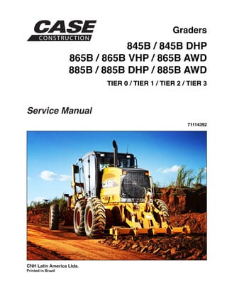
- The document provides information on troubleshooting and repair of Tier 3 engines used in CNH grader models, including failures diagnosis, component descriptions, specifications and torque values.
- Engine identification codes, properties, and general specifications are listed to identify the engine model.
- Components of the crankshaft mechanism and cylinder set are described along with the valve mechanism.
- Diagnostics are provided for common engine issues like failing to start, overheating, lack of power, smoking, knocking, dying, oil pressure problems and excessive fuel consumption.
"Trans Failsafe Prog" on your BMW X5 indicates potential transmission issues requiring immediate action. This safety feature activates in response to abnormalities like low fluid levels, leaks, faulty sensors, electrical or mechanical failures, and overheating.
𝘼𝙣𝙩𝙞𝙦𝙪𝙚 𝙋𝙡𝙖𝙨𝙩𝙞𝙘 𝙏𝙧𝙖𝙙𝙚𝙧𝙨 𝙞𝙨 𝙫𝙚𝙧𝙮 𝙛𝙖𝙢𝙤𝙪𝙨 𝙛𝙤𝙧 𝙢𝙖𝙣𝙪𝙛𝙖𝙘𝙩𝙪𝙧𝙞𝙣𝙜 𝙩𝙝𝙚𝙞𝙧 𝙥𝙧𝙤𝙙𝙪𝙘𝙩𝙨. 𝙒𝙚 𝙝𝙖𝙫𝙚 𝙖𝙡𝙡 𝙩𝙝𝙚 𝙥𝙡𝙖𝙨𝙩𝙞𝙘 𝙜𝙧𝙖𝙣𝙪𝙡𝙚𝙨 𝙪𝙨𝙚𝙙 𝙞𝙣 𝙖𝙪𝙩𝙤𝙢𝙤𝙩𝙞𝙫𝙚 𝙖𝙣𝙙 𝙖𝙪𝙩𝙤 𝙥𝙖𝙧𝙩𝙨 𝙖𝙣𝙙 𝙖𝙡𝙡 𝙩𝙝𝙚 𝙛𝙖𝙢𝙤𝙪𝙨 𝙘𝙤𝙢𝙥𝙖𝙣𝙞𝙚𝙨 𝙗𝙪𝙮 𝙩𝙝𝙚 𝙜𝙧𝙖𝙣𝙪𝙡𝙚𝙨 𝙛𝙧𝙤𝙢 𝙪𝙨.
Over the 10 years, we have gained a strong foothold in the market due to our range's high quality, competitive prices, and time-lined delivery schedules.
In this presentation, we have discussed a very important feature of BMW X5 cars… the Comfort Access. Things that can significantly limit its functionality. And things that you can try to restore the functionality of such a convenient feature of your vehicle.
What Does the PARKTRONIC Inoperative, See Owner's Manual Message Mean for You...Autohaus Service and Sales
Learn what "PARKTRONIC Inoperative, See Owner's Manual" means for your Mercedes-Benz. This message indicates a malfunction in the parking assistance system, potentially due to sensor issues or electrical faults. Prompt attention is crucial to ensure safety and functionality. Follow steps outlined for diagnosis and repair in the owner's manual.
Symptoms like intermittent starting and key recognition errors signal potential problems with your Mercedes’ EIS. Use diagnostic steps like error code checks and spare key tests. Professional diagnosis and solutions like EIS replacement ensure safe driving. Consult a qualified technician for accurate diagnosis and repair.
Ever been troubled by the blinking sign and didn’t know what to do?
Here’s a handy guide to dashboard symbols so that you’ll never be confused again!
Save them for later and save the trouble!
What Exactly Is The Common Rail Direct Injection System & How Does It WorkMotor Cars International
Learn about Common Rail Direct Injection (CRDi) - the revolutionary technology that has made diesel engines more efficient. Explore its workings, advantages like enhanced fuel efficiency and increased power output, along with drawbacks such as complexity and higher initial cost. Compare CRDi with traditional diesel engines and discover why it's the preferred choice for modern engines.
Things to remember while upgrading the brakes of your carjennifermiller8137
Upgrading the brakes of your car? Keep these things in mind before doing so. Additionally, start using an OBD 2 GPS tracker so that you never miss a vehicle maintenance appointment. On top of this, a car GPS tracker will also let you master good driving habits that will let you increase the operational life of your car’s brakes.
5 Warning Signs Your BMW's Intelligent Battery Sensor Needs AttentionBertini's German Motors
IBS monitors and manages your BMW’s battery performance. If it malfunctions, you will have to deal with an array of electrical issues in your vehicle. Recognize warning signs like dimming headlights, frequent battery replacements, and electrical malfunctions to address potential IBS issues promptly.
Why Is Your BMW X3 Hood Not Responding To Release CommandsDart Auto
Experiencing difficulty opening your BMW X3's hood? This guide explores potential issues like mechanical obstruction, hood release mechanism failure, electrical problems, and emergency release malfunctions. Troubleshooting tips include basic checks, clearing obstructions, applying pressure, and using the emergency release.
Fleet management these days is next to impossible without connected vehicle solutions. Why? Well, fleet trackers and accompanying connected vehicle management solutions tend to offer quite a few hard-to-ignore benefits to fleet managers and businesses alike. Let’s check them out!
Comprehensive program for Agricultural Finance, the Automotive Sector, and Empowerment . We will define the full scope and provide a detailed two-week plan for identifying strategic partners in each area within Limpopo, including target areas.:
1. Agricultural : Supporting Primary and Secondary Agriculture
• Scope: Provide support solutions to enhance agricultural productivity and sustainability.
• Target Areas: Polokwane, Tzaneen, Thohoyandou, Makhado, and Giyani.
2. Automotive Sector: Partnerships with Mechanics and Panel Beater Shops
• Scope: Develop collaborations with automotive service providers to improve service quality and business operations.
• Target Areas: Polokwane, Lephalale, Mokopane, Phalaborwa, and Bela-Bela.
3. Empowerment : Focusing on Women Empowerment
• Scope: Provide business support support and training to women-owned businesses, promoting economic inclusion.
• Target Areas: Polokwane, Thohoyandou, Musina, Burgersfort, and Louis Trichardt.
We will also prioritize Industrial Economic Zone areas and their priorities.
Sign up on https://profilesmes.online/welcome/
To be eligible:
1. You must have a registered business and operate in Limpopo
2. Generate revenue
3. Sectors : Agriculture ( primary and secondary) and Automative
Women and Youth are encouraged to apply even if you don't fall in those sectors.
6. 6-46530 ENG Issued 07-11 Printed in Brazil
1001-2
NOTE: CASE reserves the right to make improvements in design or changes in specifications at any time
without incurring any obligation to install them on units previously sold.
TORQUE SPECIFICATIONS.........................................................................................................................................................3
Decimal....................................................................................................................................................................................3
Métric.......................................................................................................................................................................................4
Steel Hydraulic Fittings............................................................................................................................................................5
Steel Hydraulic Fittings............................................................................................................................................................6
TABLE OF CONTENTS
7. 6-46530 ENG Issued 07-11 Printed in Brazil
1001-3
TORQUE SPECIFICATIONS
Decimal
Use the torques in this chart when special torques are not given. These torques apply to fasteners with both UNC and UNF thre-
ads as received from suppliers dry, or when lubricated with engine oil. Not applicable if special graphities, Molydisulfide greases,
or other extreme pressure lubricants are used.
Grade 5 Bolts, Nuts and Studs
Size (inch) Pound-Inches N.m
1/4 9 - 11 12 - 15
5/16 17 - 21 23 - 28
3/8 35 - 42 48 - 57
7/16 54 - 64 73 - 87
1/2 80 - 96 109 - 130
9/16 110 - 132 149 - 179
5/8 150 - 180 203 - 244
3/4 270 - 324 366 - 439
7/8 400 - 480 542 - 651
1.0 580 - 696 787 - 944
1-1/8 800 - 880 1085 - 1193
1-1/4 1120 - 1240 1519 - 1681
1-3/8 1460 - 1680 1980 - 2278
1-1/2 1940 - 2200 2631 - 2983
Grade 8 Bolts, Nuts and Studs
Size (inch) Pound-Inches N.m
1/4 12 - 15 16 - 20
5/16 24 - 29 33 - 39
3/8 45 - 54 61 - 73
7/16 70 - 84 95 - 114
1/2 110 - 132 149 - 179
9/16 160 - 192 217 - 260
5/8 220 - 264 298 - 358
3/4 380 - 456 515 - 618
7/8 600 - 720 814 - 976
1.0 900 - 1080 1220 - 1465
1-1/8 1280 - 1440 1736 - 1953
1-1/4 1820 - 2000 2468 - 2712
1-3/8 2380 - 2720 3227 - 3688
1-1/2 3160 - 3560 4285 - 4827
NOTE: Use thick nuts with Grade 8 bolts.
8. 6-46530 ENG Issued 07-11 Printed in Brazil
1001-4
Métric
Use the following torques when specifications are not given. These values apply to fasteners with coarse threads as received
from supplier, plated or unplated, or when lubricated with engine oil. These values do not apply if graphite or Molydisulfide gre-
ase or oil is used.
Grade 8.8 Bolts, Nuts and Studs
8.8
Size (inch) Pound-Inches N.m
M4 2 - 3 3 - 4
M5 5 - 6 6.5 - 8
M6 8 - 9 10.5 - 12
M8 19 - 23 26 - 31
M10 38 - 45 52 - 61
M12 66 - 79 90 - 107
M14 106 - 127 144 - 172
M16 160 - 200 217 - 271
M20 320 - 380 434 - 515
M24 500 - 600 675 - 815
M30 920 - 1100 1250 - 1500
M36 1600 - 1950 2175 - 2600
Grade 10.9 Bolts, Nuts and Studs
10.9
Size (inch) Pound-Inches N.m
M4 3 - 4 4 - 5
M5 7 - 8 9.5 - 11
M6 11 - 13 15 - 17.5
M8 27 - 32 37 - 43
M10 54 - 64 73 - 87
M12 93 - 112 125 - 152
M14 149 - 179 300 - 245
M16 230 - 280 310 - 380
M20 450 - 540 610 - 730
M24 780 - 940 1050 - 1275
M30 1470 - 1770 2000 - 2400
M36 2580 - 3090 3500 - 4200
Grade 12.9 Bolts, Nuts and Studs
12.9
Usually the torque values specified for grade 10.9 faste-
ners. can be used satisfactorily on grade 12.9 fasteners.
11. 6-46557 ENG Issued 07-11 Printed in Brazil
2002-2
ENGINE DIAGNOSTIC TOOL........................................................................................................................................................6
FAILS DIAGNOSTICS....................................................................................................................................................................7
Engine Fails to Start................................................................................................................................................................7
Engine Overheating.................................................................................................................................................................8
Engine Lacks Power and Operates Irregularly........................................................................................................................9
Engine Smokes Black or Dark Grey......................................................................................................................................10
Engine Smokes (Tending to White).......................................................................................................................................10
Engine Smokes Light Blue....................................................................................................................................................10
Engine Knocks Abnormally....................................................................................................................................................11
The Engine Dies....................................................................................................................................................................12
Excessive or Insufficient Oil Pressure...................................................................................................................................12
Excessive Fuel Consumption................................................................................................................................................12
ENGINE........................................................................................................................................................................................13
Identification Code.................................................................................................................................................................14
Properties..............................................................................................................................................................................14
General Specifications......................................................................................................................................................15
CRANKSHAFT MECHANISM COMPONENTS AND CYLINDERS SET.....................................................................................17
VALVE MECHANISM – CYLINDER SET.....................................................................................................................................20
SPECIAL TOOLS.........................................................................................................................................................................22
TIGHTENNING TORQUES..........................................................................................................................................................23
667TA ENGINES..........................................................................................................................................................................25
DESCRIPTION OF ENGINE MAIN COMPONENTS...................................................................................................................26
Engine Block..........................................................................................................................................................................26
Crankshaft.............................................................................................................................................................................27
Connecting Rod.....................................................................................................................................................................28
Piston.....................................................................................................................................................................................29
Camshaft...............................................................................................................................................................................30
Exhaust Gas Recirculation - EGR.........................................................................................................................................30
Valve Control.........................................................................................................................................................................31
Cylinder Head of Engines – 667TA/EBF – 667TA/EBD – 667TA/EED..................................................................................32
Cylinder Head of Engines – 667TA/EEG – 667TA/EEC........................................................................................................33
Cylinder Head of Engines – 667TA/EDJ................................................................................................................................34
Valves and Valves Seats.......................................................................................................................................................35
Valves Bridge.........................................................................................................................................................................35
Cylinder Head Machining......................................................................................................................................................36
Engine Flywheel....................................................................................................................................................................36
AUXILIARY DEVICES DRIVING..................................................................................................................................................37
ENGINE LUBRICATION...............................................................................................................................................................38
Oil Coller................................................................................................................................................................................39
Oil Pressure Control Valve.....................................................................................................................................................39
Deviation Valve......................................................................................................................................................................39
Oil Pump................................................................................................................................................................................40
Oil Sump of Engines – 667TA/EEG – 667TA/EEC – 667TA/EBF – 667TA/EED – 667TA/EDJ.............................................41
Oil Sump of Engines – 667TA/EED – 667TA/EBD................................................................................................................41
Blow-By.................................................................................................................................................................................42
ENGINE COOLER.......................................................................................................................................................................43
Water Pump...........................................................................................................................................................................44
COMMON RAIL – HIGH PRESSURE ELECTRONIC INJECTION SYSTEM..............................................................................45
TABLE OF CONTENTS
12. 6-46557 ENG Issued 07-11 Printed in Brazil
2002-3
EDC7UC31 – ELECTRONIC CONTROL UNIT OPERATION......................................................................................................46
Engine Pre-Post Heater Control............................................................................................................................................46
Phase Recognition................................................................................................................................................................46
Injection Control.....................................................................................................................................................................46
Closed Mesh Injection Pressure Control System..................................................................................................................46
Main Control and Main Injection Advance Control.................................................................................................................46
Idle Control............................................................................................................................................................................46
Overheating Protection..........................................................................................................................................................46
Engine Maximum Rotation Limit............................................................................................................................................46
Cut-Off...................................................................................................................................................................................46
Smoke Control Under Acceleration.......................................................................................................................................46
After Engine Cut-Off..............................................................................................................................................................46
Work Rotation Control in Normal Operation Conditions........................................................................................................46
Recovery Strategy.................................................................................................................................................................47
FUEL SUPPLY SISTEM...............................................................................................................................................................48
Fuel Supply System Diagram................................................................................................................................................49
Fuel Filter...............................................................................................................................................................................50
Mechanical Supply Pump – Normal Operation Condition.....................................................................................................51
Mechanical Supply Pump – Unit Exit Overpressure Condition..............................................................................................51
Bleeding Condition of the Fuel System.................................................................................................................................52
High Pressure Pump CP3.3 TYPE........................................................................................................................................53
High Pressure Pump Exploded View.....................................................................................................................................54
High Pressure Pump Internal View........................................................................................................................................55
Operation...............................................................................................................................................................................56
Operation Theory...................................................................................................................................................................58
Common Rail............................................................................................................................................................................59
Common Rail Pressure Relief Valve......................................................................................................................................60
ELECTROINJECTOR...................................................................................................................................................................61
Injector in Rest Position.........................................................................................................................................................61
Injection Starts.......................................................................................................................................................................61
Injection End..........................................................................................................................................................................61
Injector Nozzler......................................................................................................................................................................62
Fuel Return Pressure Limiter.................................................................................................................................................62
LOCATION OF MAIN ELECTRICAL COMPONENTS..................................................................................................................63
EDC7UC31 – Electronic Control Unit....................................................................................................................................64
Engine Pin-Out......................................................................................................................................................................65
Injectors Connector A Pin-Out Diagram.................................................................................................................................66
Injectors Connector C Pin-Out Diagram................................................................................................................................66
Cranckshaft Sensor...............................................................................................................................................................67
Camshaft Sensor...................................................................................................................................................................67
Pressure and Temperature Sensor........................................................................................................................................68
Engine Oil Pressure and Temperature Sensor......................................................................................................................68
Common Rail – Fuel Pressure Sensor..................................................................................................................................69
Electroinjector........................................................................................................................................................................70
Intake Air Resistance Heater and Rele..................................................................................................................................71
Fuel Temperature Sensor......................................................................................................................................................72
Filter Heater Rele..................................................................................................................................................................72
High Pressure Pump – Pressure Regulator..........................................................................................................................73
13. 6-46557 ENG Issued 07-11 Printed in Brazil
2002-4
FUEL SYSTEM CHECK...............................................................................................................................................................74
High Pressure Supply Test....................................................................................................................................................74
Low Pressure Pump..............................................................................................................................................................75
Common Rail Pressure Relief Valve Test..............................................................................................................................76
Fuel Counter-Flow Test from the Return................................................................................................................................77
ENGINE OVERHAULING IN BENCH..........................................................................................................................................79
Engine Disassembly..............................................................................................................................................................79
ENGINE BLOCK CHECKS AND SPECIFICATIONS...................................................................................................................91
Checks And Measurement....................................................................................................................................................91
Camshaft Lobe And Journal Surface Check..........................................................................................................................91
Bearigns................................................................................................................................................................................92
Checking The Contact Surface Between Cylinder Head And Cylinder Block........................................................................93
Camshaft Syncronism...........................................................................................................................................................93
Lobe Bearing Replacement...................................................................................................................................................94
Tappets..................................................................................................................................................................................94
Camshaft Tappets Installation................................................................................................................................................95
CRANCKSHAFT...........................................................................................................................................................................97
Cranckshaft Journal Measurement........................................................................................................................................97
Cranckshaft Journals Marking Data......................................................................................................................................97
Cranckshaft Main Tolerances................................................................................................................................................98
Oil Pump Gears Replacement...............................................................................................................................................99
Main Bearings Installation.....................................................................................................................................................99
Journals Assembly Clearance Measurement......................................................................................................................100
Cranckshaft Recess Clearance Measurement....................................................................................................................101
Connecting Rod – Piston Set..............................................................................................................................................101
Piston, Pin and Piston Ring Data........................................................................................................................................102
Piston Pin Diameter Measurement......................................................................................................................................103
Piston Pin............................................................................................................................................................................103
Pin-Piston Correct Mating Condition...................................................................................................................................103
Piston Rings........................................................................................................................................................................104
Connecting Rod...................................................................................................................................................................105
Bearings..............................................................................................................................................................................106
Connecting Rod Check........................................................................................................................................................106
Torsion Check......................................................................................................................................................................107
Flexibility Check...................................................................................................................................................................107
Connecting Rod – Piston Set Coupling Installation.............................................................................................................108
Piston Rings Installation......................................................................................................................................................109
Connecting Rods-Piston Sets – Installation in Cylinder Block.............................................................................................109
Journal Clearance Measurement in Cranckshaft Set..........................................................................................................110
Piston Outgrowth Check......................................................................................................................................................112
Timing Gear Housing...........................................................................................................................................................112
Valve Syncronism................................................................................................................................................................113
Engine Flywell Housing.......................................................................................................................................................114
ENGINE FLYWHEEL..................................................................................................................................................................115
Replacement of the Engine Flywheel Annular Gear............................................................................................................115
CYLINDER HEAD......................................................................................................................................................................121
Valve Remotion....................................................................................................................................................................121
Cylinder Head Water Sealing Check...................................................................................................................................122
Cylinder Head Contact Surface Sealing..............................................................................................................................122
14. 6-46557 ENG Issued 07-11 Printed in Brazil
2002-5
VALVES......................................................................................................................................................................................123
Cleaning, Checking and Valve Rectification........................................................................................................................123
Assembling Clearance Checking and Valve Centralization.................................................................................................123
VALVE GUIDES..........................................................................................................................................................................124
VALVE SEATS............................................................................................................................................................................125
Cylinder Head Valve Seat Main Data..................................................................................................................................125
Cylinder Head Valve Seat Main Data..................................................................................................................................126
VALVE SPRINGS.......................................................................................................................................................................127
Main Data Check of Intake and Exhaust Valve Springs......................................................................................................127
CYLINDER HEAD......................................................................................................................................................................128
Cylinder Head Installation....................................................................................................................................................129
Injectors Installation.............................................................................................................................................................130
Pushrods and Tappets.........................................................................................................................................................131
Rocker Set...........................................................................................................................................................................132
Locating the Top Dead Center (TDC)..................................................................................................................................133
Valve Clearance Adjust........................................................................................................................................................134
Wiring Harness Connection to Engine.................................................................................................................................139
STARTER...................................................................................................................................................................................141
Quick Diagnosys..................................................................................................................................................................141
Starter Bosch 24 Volts – 4KW.............................................................................................................................................142
Starter Iskra 24 Volts – 4KW...............................................................................................................................................143
Starter Denso 24 Volts – 7,8KW..........................................................................................................................................143
ALTERNATOR............................................................................................................................................................................144
Quick Diagnosys..................................................................................................................................................................144
Bosch: NCBI 28 Volt 35-70 AMP.........................................................................................................................................145
Starter Remotion.................................................................................................................................................................146
Starter Installation................................................................................................................................................................147
Alternator Remotion.............................................................................................................................................................148
Alternator Installation...........................................................................................................................................................150
Belt Installation....................................................................................................................................................................152
15. 6-46557 ENG Issued 07-11 Printed in Brazil
2002-25
667TA ENGINES
BS06K020 Figura 3000-12
Turbocharger1.
Automatic tension belt2.
Alternator3.
Fix guide pulley4.
Water pump5.
Engine flywheel counterweight6.
Oil sump7.
Electronic Control Unit - E.C.U.8.
Fuel filter9.
High pressure pump10.
Common Rail11.
16. 6-46557 ENG Issued 07-11 Printed in Brazil
2002-26
DESCRIPTION OF ENGINE MAIN COMPONENTS
Engine Block
The cylinder block is a cast iron structure with cylinders bores (1), main journals (5) e moun-tings for camshaft bearing
(3) and valves, water-oil exchanger heater (7), water pump (2) and oil pump (4). The block also has coolant and oil
passages. The lubrication circuit provides oil for the moving parts. The stiffening plate (6) is applied in the engine
block botton to increase the resistance to mechanical fatigue.
Cylinder bore1.
Mounting for water pump2.
Mounting for Camshaft bearing3.
Mounting for oil pump4.
Main journals5.
Stiffening plate6.
Mounting for water-oil exchange heater7.
17. 6-46557 ENG Issued 07-11 Printed in Brazil
2002-27
Crankshaft
BS06K022 Figura 3000-14
Oil pump gear1.
Crankshaft2.
Timing gear3.
Mounting for engine flywheel4.
The crankshaft is steel made and rests in seven journals tempered by induction.
There is a series of drilled passages for the lubricating oil.
The follow items are pressed in front: oil pump gear (1), position sensor sprocket, counterweight,
and the auxiliary devices pulley.
The follow items are pressed in rear: timing gear (3), and the mounting for engine flywheel (4).
The main journals bearings are steel made and coated by a anti-friction alloy. One of them is equipped with shoulders
to limit the cranckshaft axial clearance.
The timing gear (3) and the engine flywheel mounting (4) are forced positioned in the cranckshaft
rear and can not be replaced.
CRANCKSHAFT OIL SEALS
The front and rear seals are box type with radial sealing. To remove them use the special tools 380000665 e
380000663. For installation se special tools 380000666 e 380000664.
18. 6-46557 ENG Issued 07-11 Printed in Brazil
2002-28
Connecting Rod
BS06K023 Figura 3000-15
Connecting rods are forged steel. The big ends are made with an oblique angle. Caps and rods are separeted by a
fracture splitting method that produces a strong and unique fit cap.
The connecting rod big end bearings are coated by anti-friction alloy.
They are marked two ways:
Body-cap: have a number that indicates match and cylinder which they are assembled.•
Rod shank: marked with a letter indicating weight class.•
19. 6-46557 ENG Issued 07-11 Printed in Brazil
2002-29
A coroa na cabeça do pistão apresenta uma câmara de combustão de alta turbulência. A parte inferior da coroa
na cabeça do pistão é arrefecida pelo óleo do motor distribuído por um bico pulverizador instalado no bloco do
motor.
Existem três canaletas para anéis do pistão com diferentes funções e diferente geometria:
The piston crown features a high turbulence combustion chamber. The piston crown is cooled from underneath by
a spray nozzle installed in the cranckcase.
There is three groves for piston rings with different functions and different geometry:
1st pinston ring with trapezoidal section (keystone) and coated by chome ceramic.•
2ndt piston ring with torsional conical rectangular section.•
3rd piston ring with double oil scraper and inner spring.•
In the piston crown are marked the reference data:
Number of spare part and number of design modification.1.
Mark (looking from the frontal engine block) indicating the direction of assembly of the piston in the cylinder2.
Date of manufacture.3.
Mark indicating the first test of the recess insert.4.
Piston
BS06K024 Figura 3000-16
20. 6-46557 ENG Issued 07-11 Printed in Brazil
2002-30
Camshaft
BS06K025 Figura 3000-17
BS06K026 Figura 3000-18
Intake valve lobeA.
Exhaust valve lobeB.
Lobe EGRC.
Camshaft is supported by seven journals in the engine block.
The front and rear journals seats are equipped with steel bushings coated with anti-friction material forced
positioned.
There is two lobes for each cylinder
Intake lobeA.
Exhaust lobeB.
Camshaft is directly controlled by rear gears moved by the crankshaft.
Exhaust Gas Recirculation - EGR
The exhaust gas can return partially to the cylinder and reduce the maximum temperature res-ponsible caused by
the nitrogen oxide (NOx) generation.
The ECR reduces the combustion temperature, decreasing the oxigen concentration in the combustion chamber,
creating a efficient system to control the NOx emissions. The EGR lobe is not equipped with any electronic control,
and the system is always enabled. Its configuration do not requires aditional elements such as retaining valve, pipes
or heat dissipation.
There is an aditional lobe (C). When a cylinder is intaking, this lobe allow a brief opening of the exhaust valve. The
recirculation occurs in that cylinder due the great exhaust pressure compared to the intake gases.
21. Thank you very much for
your reading. Please Click
Here. Then Get COMPLETE
MANUAL. NO WAITING
NOTE:
If there is no response to
click on the link above,
please download the PDF
document first and then
click on it.
22. 6-46557 ENG Issued 07-11 Printed in Brazil
2002-31
Valve Control
BS06K027 Figura 3000-19
Rocker1.
Valve clearance adjusting screw2.
Pushrod3.
Valve cone4.
Valve seat5.
Spring6.
Camshaft7.
Tappet8.
Bridge9.
Rocker axle10.
23. 6-46557 ENG Issued 07-11 Printed in Brazil
2002-32
Cylinder Head of Engines – 667TA/EBF – 667TA/EBD – 667TA/EED
The cast iron cylinder head is machined to allow mounting the following parts:
Valve seats (4).•
Injectors (2).•
Thermostat (3).•
It is designed also to accommodate the following components:
Exhaust manifold (1).•
Intake manifold (6) with intake air heater mounting (5).•
Exhaust manifold1.
Injector2.
Thermostat3.
Valve seat4.
Intake air heater5.
Intake manifold6.
24. 6-46557 ENG Issued 07-11 Printed in Brazil
2002-33
Cylinder Head of Engines – 667TA/EEG – 667TA/EEC
Exhaust manifold1.
Injector2.
Thermostat3.
Valve seat4.
Injectors electrical cable support5.
Intake air heater6.
Intake manifold7.
The cast iron cylinder head is machined to allow mounting the following parts:
Valve seats (4)•
Injectors (2)•
Thermostat (3)•
It is designed also to accommodate the following components:
Exhaust manifold (1)•
Intake manifold (7) with intake air heater mounting (6)•