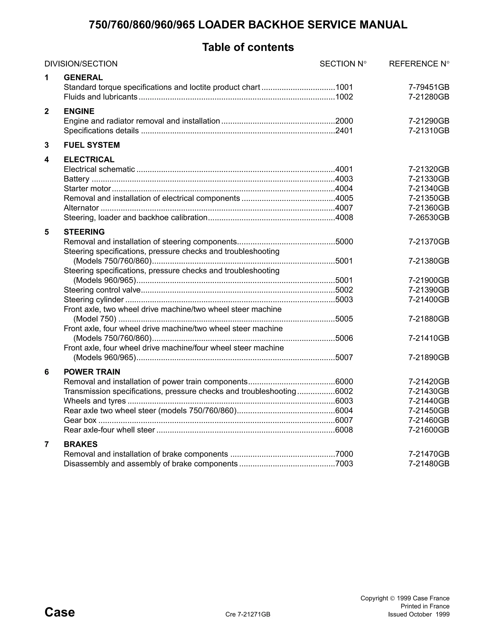
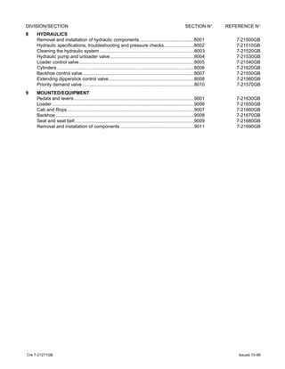
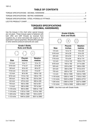
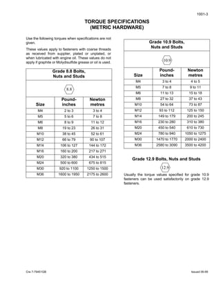
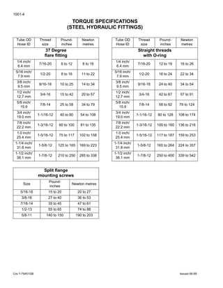
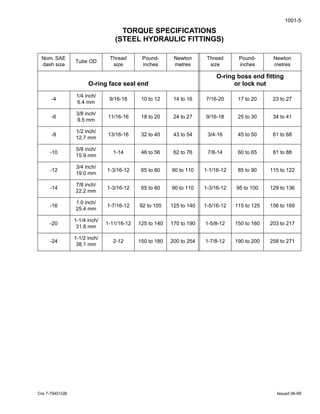
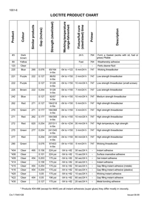
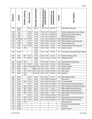
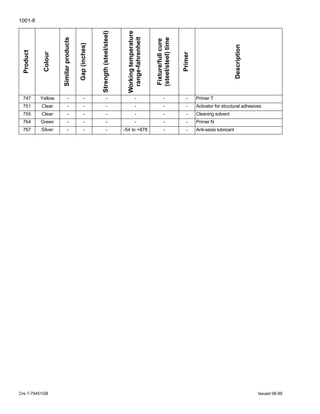
This is the Highly Detailed factory service repair manual for theCASE 860 BACKHOE LOADER, this Service Manual has detailed illustrations as well as step by step instructions,It is 100 percents complete and intact. they are specifically written for the do-it-yourself-er as well as the experienced mechanic.CASE 860 BACKHOE LOADER Service Repair Workshop Manual provides step-by-step instructions based on the complete dis-assembly of the machine. It is this level of detail, along with hundreds of photos and illustrations, that guide the reader through each service and repair procedure. Complete download comes in pdf format which can work under all PC based windows operating system and Mac also, All pages are printable. Using this repair manual is an inexpensive way to keep your vehicle working properly.
Service Repair Manual Covers:
General
Engine
Fuel System
Electrical
Steering
Power Train
Brake
Hydraulics
Mounted
Equipment
File Format: PDF
Compatible: All Versions of Windows & Mac
Language: English
Requirements: Adobe PDF Reader
NO waiting, Buy from responsible seller and get INSTANT DOWNLOAD, Without wasting your hard-owned money on uncertainty or surprise! All pages are is great to haveCASE 860 BACKHOE LOADER Service Repair Workshop Manual.
Looking for some other Service Repair Manual,please check:
https://www.aservicemanualpdf.com/
Thanks for visiting!
BOBCAT E55 COMPACT EXCAVATOR Service Repair Manual SN:AJ1911001 AND Abovejkmsrremmd
This is the Highly Detailed factory service repair manual for theBOBCAT E55 COMPACT EXCAVATOR , this Service Manual has detailed illustrations as well as step by step instructions,It is 100 percents complete and intact. they are specifically written for the do-it-yourself-er as well as the experienced mechanic.BOBCAT E55 COMPACT EXCAVATOR Service Repair Workshop Manual provides step-by-step instructions based on the complete dis-assembly of the machine. It is this level of detail, along with hundreds of photos and illustrations, that guide the reader through each service and repair procedure. Complete download comes in pdf format which can work under all PC based windows operating system and Mac also, All pages are printable. Using this repair manual is an inexpensive way to keep your vehicle working properly.
Service Repair Manual Covers:
Safety and Maintenance
Hydraulic System
Undercarriage
Upperstructure and Swing Section
Electrical System and Analysis
Engine Service
Heating, Ventilation and Air Conditioning
Specifications
Alphabetical Index
File Format: PDF
Compatible: All Versions of Windows & Mac
Language: English
Requirements: Adobe PDF Reader
NO waiting, Buy from responsible seller and get INSTANT DOWNLOAD, Without wasting your hard-owned money on uncertainty or surprise! All pages are is great to haveBOBCAT E55 COMPACT EXCAVATOR Service Repair Workshop Manual.
Looking for some other Service Repair Manual,please check:
https://www.aservicemanualpdf.com/
Thanks for visiting!
8
El documento describe diferentes formas de notificar autos y providencias judiciales como la notificación personal, por aviso, por estado, por conducta concluyente y emplazamiento. Explica que la notificación personal se realiza a entidades públicas, funcionarios públicos y personas inscritas en el registro mercantil, mientras que la notificación por aviso se usa cuando no es posible la personal. La notificación por estado implica fijar la providencia en la secretaría judicial. La notificación por conducta concluyente ocurre cuando una parte actúa a través de
Este documento resume las características de las contribuciones especiales en el derecho tributario venezolano. Menciona que las contribuciones especiales son tributos debidos por beneficios individuales o de grupos derivados de obras públicas. Da ejemplos como las contribuciones de mejoras y de seguridad social. Explica que las contribuciones de seguridad social financian entidades como el Seguro Social e INCES a través de aportes de empleadores y empleados.
CASE 821F TIER 4 WHEEL LOADER Service Repair Manualuekdjkm jksemmd
This is the Highly Detailed factory service repair manual for theCASE 821F TIER 4 WHEEL LOADER, this Service Manual has detailed illustrations as well as step by step instructions,It is 100 percents complete and intact. they are specifically written for the do-it-yourself-er as well as the experienced mechanic.CASE 821F TIER 4 WHEEL LOADER Service Repair Workshop Manual provides step-by-step instructions based on the complete dis-assembly of the machine. It is this level of detail, along with hundreds of photos and illustrations, that guide the reader through each service and repair procedure. Complete download comes in pdf format which can work under all PC based windows operating system and Mac also, All pages are printable. Using this repair manual is an inexpensive way to keep your vehicle working properly.
Service Repair Manual Covers:
General Information
Engine
Electrical System
Undercarriage
Drive Train
Undercarriage Hydraulics
Upperstructure Hydraulics
Upperstructure
Electrical Schematic
Hydraulic Schematic – 821F
Hydraulic Schematic – 921F
File Format: PDF
Compatible: All Versions of Windows & Mac
Language: English
Requirements: Adobe PDF Reader
NO waiting, Buy from responsible seller and get INSTANT DOWNLOAD, Without wasting your hard-owned money on uncertainty or surprise! All pages are is great to haveCASE 821F TIER 4 WHEEL LOADER Service Repair Workshop Manual.
Looking for some other Service Repair Manual,please check:
https://www.aservicemanualpdf.com/
Thanks for visiting!
New holland w130 c tier 4 wheel loader service repair manualfjkskmmdmme
This section describes the removal and installation procedures for the engine and radiator on a W130C wheel loader. The key steps for engine removal include disconnecting batteries, draining fluids, removing accessories, and using an engine lifting fixture to remove the engine from the vehicle. Installation is largely the reverse of removal. Procedures for radiator removal include draining coolant and removing mounting brackets, and installation is the reverse of removal. Torque specifications are provided for relevant fasteners.
New Holland W130C Tier 4 Wheel Loader Service Repair Manual.pdffusedkdd9idi
This section describes the removal and installation procedures for the engine and radiator on a W130C wheel loader. The key steps for engine removal include disconnecting batteries, draining fluids, removing mounting brackets and hoses. Installation is the reverse of removal. Radiator removal involves disconnecting hoses and electrical connections, and removing mounting bolts. Installation is also the reverse of removal. Torque specifications are provided for critical fasteners.
New Holland W130C Tier 4 Wheel Loader Service Repair Manual.pdfcheng576587ce
This section describes the removal and installation procedures for the engine and radiator on a W130C wheel loader. The key steps for engine removal include disconnecting batteries, draining fluids, removing accessories, and using an engine lifting fixture to remove the engine from the vehicle. Installation is largely the reverse of removal. Procedures for radiator removal include draining coolant and removing mounting brackets, and installation is the reverse of removal. Torque specifications are provided for relevant fasteners.
New holland w130 c tier 4 wheel loader service repair manual instant downloadudfjsjjekkekmem
This section describes the removal and installation procedures for the engine and radiator on a W130C wheel loader. The key steps for engine removal include disconnecting batteries, draining fluids, removing accessories, and using an engine lifting fixture to remove the engine from the vehicle. Installation is largely the reverse of removal. Procedures for radiator removal include draining coolant and removing mounting brackets, and installation is the reverse of removal. Torque specifications are provided for reinstalling components.
New Holland W130C Tier 4 Wheel Loader Service Repair Manual.pdffujksekd9dokd
This section describes the removal and installation procedures for the engine and radiator on a W130C wheel loader. The key steps for engine removal include disconnecting batteries, draining fluids, removing mounting brackets and hoses. Installation is the reverse of removal. Radiator removal involves disconnecting hoses and electrical connections, then removing mounting bolts. Installation is also reverse of removal. Torque specifications are provided for correct reinstallation of components.
New holland w130 c tier 4 wheel loader service repair manualfujsjefkskem
This section describes the removal and installation procedures for the engine and radiator on a W130C wheel loader. The key steps for engine removal include disconnecting batteries, draining fluids, removing mounting brackets and hoses. Installation is the reverse of removal. Radiator removal involves disconnecting hoses and electrical connections, then removing mounting bolts. Installation is also reverse of removal. Torque specifications are provided for correct reinstallation of components.
New holland w130 c tier 4 wheel loader service repair manualujfjjkskkmdme
This section describes the removal and installation procedures for the engine and radiator on a W130C wheel loader. The key steps for engine removal include disconnecting batteries, draining fluids, removing mounting brackets and hoses. Installation is the reverse of removal. Radiator removal involves disconnecting hoses and electrical connections, and removing mounting bolts. Installation is also the reverse of removal. Torque specifications are provided for critical fasteners.
New Holland W130C Tier 4 Wheel Loader Service Repair Manual.pdfhmc151121
This section describes the removal and installation procedures for the engine and radiator on a W130C wheel loader. The key steps for engine removal include disconnecting batteries, draining fluids, removing mounting brackets and hoses. Installation is the reverse of removal. Radiator removal involves disconnecting hoses and electrical connections, and removing mounting bolts. Installation is also the reverse of removal. Torque specifications are provided for critical fasteners.
New holland w130 c tier 4 wheel loader service repair manualuufdjjjskkemm
This section describes the removal and installation procedures for the engine and radiator on a W130C wheel loader. The procedures include disconnecting battery ground cables, draining coolant and fuel, removing mounting bolts and hoses, and lifting the engine from the vehicle. Reinstallation involves lowering the engine back into position and reconnecting all hoses, brackets, and electrical components. Proper torque specifications are provided for all fasteners.
New holland w130 c tier 4 wheel loader service repair manualfikskefjsekfsem
This section describes the removal and installation procedures for the engine and radiator on a W130C wheel loader. The procedures include draining fluids, disconnecting linkages, removing mounting hardware, and installing in the reverse order. Specifications and torque values are provided for reinstalling components.
New Holland W130C Tier 4 Wheel Loader Service Repair Manual.pdff8seujdjkddm
This section describes the removal and installation procedures for the engine and radiator on a W130C wheel loader. The key steps for engine removal include disconnecting batteries, draining fluids, removing mounting brackets and hoses. Installation is the reverse of removal. Radiator removal involves disconnecting hoses and electrical connections, and removing mounting bolts. Installation is also the reverse of removal. Torque specifications are provided for critical fasteners.
New Holland W130C Tier 4 Wheel Loader Service Repair Manual.pdffusjekkdkdme3
This section describes the removal and installation procedures for the engine and radiator on a W130C wheel loader. The key steps for engine removal include disconnecting batteries, draining fluids, removing mounting brackets and hoses. Installation is the reverse of removal. Radiator removal involves disconnecting hoses and electrical connections, then removing mounting bolts. Installation is also reverse of removal. Torque specifications are provided for all fasteners.
New holland w130 c tier 4 wheel loader service repair manualfjsjekdmmeme
This section describes the removal and installation procedures for the engine and radiator on a W130C wheel loader. The key steps for engine removal include disconnecting batteries, draining fluids, removing mounting brackets and hoses. Installation is the reverse of removal. Radiator removal involves disconnecting hoses and electrical connections, then removing mounting bolts. Installation is also reverse of removal. Torque specifications are provided for correct reinstallation of components.
CASE 821F 921F TIER 4 WHEEL LOADER Service Repair Manual Instant Download.pdfyan77xunhao
This document provides specifications and recommendations for fluids, lubricants, and maintenance for Case wheel loaders models 821F and 921F. It includes engine oil, coolant, fuel, and hydraulic system capacities and types for each model. It also provides general guidelines on diesel fuel, Selective Catalytic Reduction systems, maintenance schedules, and maintenance points.
Case 921 f tier 4 wheel loader service repair manualfjjskekdmem
This document provides specifications and maintenance information for Case wheel loaders models 821F and 921F, including:
- Capacities for engine oil, coolant, fuel, DEF, and hydraulic fluid for the 821F model
- Recommendations for engine oil type and diesel fuel specifications
- Information on selective catalytic reduction (SCR) systems and maintenance schedules
- Tables of torque specifications for hardware and hydraulic fittings
The document is a service manual for technicians, outlining fluid capacities, recommended lubricants, emissions system overview, and maintenance procedures for the wheel loaders.
CASE CX31B MINI EXCAVATOR Service Repair Manualjksmmd usekjdkm
This is the Highly Detailed factory service repair manual for theCASE CX31B MINI EXCAVATOR, this Service Manual has detailed illustrations as well as step by step instructions,It is 100 percents complete and intact. they are specifically written for the do-it-yourself-er as well as the experienced mechanic.CASE CX31B MINI EXCAVATOR Service Repair Workshop Manual provides step-by-step instructions based on the complete dis-assembly of the machine. It is this level of detail, along with hundreds of photos and illustrations, that guide the reader through each service and repair procedure. Complete download comes in pdf format which can work under all PC based windows operating system and Mac also, All pages are printable. Using this repair manual is an inexpensive way to keep your vehicle working properly.
Service Repair Manual Covers:
Specifications
Attachment Dimensions
Tools
Standard Maintenance Time Table
Maintenance Standards and Test Procedures
Hydraulic System
Electrical System
Components System
Whole Disassembling and Assembling
Attachments
Upper Slewing Structure
Travel System
Hydraulic System
Electrical System
Engine
Supporting Data
Applicable Machines
Electrical and Hydraulic Schematic Diagram
File Format: PDF
Compatible: All Versions of Windows & Mac
Language: English
Requirements: Adobe PDF Reader
NO waiting, Buy from responsible seller and get INSTANT DOWNLOAD, Without wasting your hard-owned money on uncertainty or surprise! All pages are is great to haveCASE CX31B MINI EXCAVATOR Service Repair Workshop Manual.
Looking for some other Service Repair Manual,please check:
https://www.aservicemanualpdf.com/
Thanks for visiting!
This is the Highly Detailed factory service repair manual for the2001 ARCTIC CAT ZL 600 EFI SNOWMOBILE, this Service Manual has detailed illustrations as well as step by step instructions,It is 100 percents complete and intact. they are specifically written for the do-it-yourself-er as well as the experienced mechanic.2001 ARCTIC CAT ZL 600 EFI SNOWMOBILE Service Repair Workshop Manual provides step-by-step instructions based on the complete dis-assembly of the machine. It is this level of detail, along with hundreds of photos and illustrations, that guide the reader through each service and repair procedure. Complete download comes in pdf format which can work under all PC based windows operating system and Mac also, All pages are printable. Using this repair manual is an inexpensive way to keep your vehicle working properly.
Service Repair Manual Covers:
File Format: PDF
Compatible: All Versions of Windows & Mac
Language: English
Requirements: Adobe PDF Reader
NO waiting, Buy from responsible seller and get INSTANT DOWNLOAD, Without wasting your hard-owned money on uncertainty or surprise! All pages are is great to have2001 ARCTIC CAT ZL 600 EFI SNOWMOBILE Service Repair Workshop Manual.
Looking for some other Service Repair Manual,please check:
https://www.aservicemanualpdf.com/
Thanks for visiting!
JCB 155 SKID STEER LOADER (ROBOT) Service Repair Manualjksmmd usekjdkm
This is the Highly Detailed factory service repair manual for theJCB 155 SKID STEER LOADER (ROBOT), this Service Manual has detailed illustrations as well as step by step instructions,It is 100 percents complete and intact. they are specifically written for the do-it-yourself-er as well as the experienced mechanic.JCB 155 SKID STEER LOADER (ROBOT) Service Repair Workshop Manual provides step-by-step instructions based on the complete dis-assembly of the machine. It is this level of detail, along with hundreds of photos and illustrations, that guide the reader through each service and repair procedure. Complete download comes in pdf format which can work under all PC based windows operating system and Mac also, All pages are printable. Using this repair manual is an inexpensive way to keep your vehicle working properly.
Covers the following serials:
135, 155, 175, 190, 205, 150T, 190T, 205T from serial number 1755000
Service Repair Manual Covers:
General Information
Care and Safety
Maintenance
Attachments
Body and Framework
Electrics
Hydraulics
Transmission
Tracks
Engine
File Format: PDF
Compatible: All Versions of Windows & Mac
Language: English
Requirements: Adobe PDF Reader
NO waiting, Buy from responsible seller and get INSTANT DOWNLOAD, Without wasting your hard-owned money on uncertainty or surprise! All pages are is great to haveJCB 155 SKID STEER LOADER (ROBOT) Service Repair Workshop Manual.
Looking for some other Service Repair Manual,please check:
https://www.aservicemanualpdf.com/
Thanks for visiting!
HITACHI ZAXIS ZX 120-3 EXCAVATOR Service Repair Manualjksmmd usekjdkm
This is the Highly Detailed factory service repair manual for theHITACHI ZAXIS ZX 120-3 EXCAVATOR, this Service Manual has detailed illustrations as well as step by step instructions,It is 100 percents complete and intact. they are specifically written for the do-it-yourself-er as well as the experienced mechanic.HITACHI ZAXIS ZX 120-3 EXCAVATOR Service Repair Workshop Manual provides step-by-step instructions based on the complete dis-assembly of the machine. It is this level of detail, along with hundreds of photos and illustrations, that guide the reader through each service and repair procedure. Complete download comes in pdf format which can work under all PC based windows operating system and Mac also, All pages are printable. Using this repair manual is an inexpensive way to keep your vehicle working properly.
Service Manual Consists of the following separate Part No:
Technical Manual (Operational Principle) Vol.No. TO1R7-E
Technical Manual (Troubleshooting) Vol.No. TT1R7-E
Workshop Manual Vol.No. W1R7-E
Workshop Manual Covers:
Safety
General Information
Upperstructure
Undercarriage
Front Attachment
Technical Manual (Operational Principle) Covers:
General
System
Component Operation
Technical Manual (Troubleshooting) Covers:
Operational Performance Test
Troubleshooting
File Format: PDF
Compatible: All Versions of Windows & Mac
Language: English
Requirements: Adobe PDF Reader
NO waiting, Buy from responsible seller and get INSTANT DOWNLOAD, Without wasting your hard-owned money on uncertainty or surprise! All pages are is great to haveHITACHI ZAXIS ZX 120-3 EXCAVATOR Service Repair Workshop Manual.
Looking for some other Service Repair Manual,please check:
https://www.aservicemanualpdf.com/
Thanks for visiting!
HITACHI ZAXIS 470H-3 EXCAVATOR Service Repair Manualjksmmd usekjdkm
This is the Highly Detailed factory service repair manual for theHITACHI ZAXIS 470H-3 EXCAVATOR, this Service Manual has detailed illustrations as well as step by step instructions,It is 100 percents complete and intact. they are specifically written for the do-it-yourself-er as well as the experienced mechanic.HITACHI ZAXIS 470H-3 EXCAVATOR Service Repair Workshop Manual provides step-by-step instructions based on the complete dis-assembly of the machine. It is this level of detail, along with hundreds of photos and illustrations, that guide the reader through each service and repair procedure. Complete download comes in pdf format which can work under all PC based windows operating system and Mac also, All pages are printable. Using this repair manual is an inexpensive way to keep your vehicle working properly.
Service Manual Consists of the following separate Part No:
Technical Manual (Operational Principle) Vol.No. TO1J1-E
Technical Manual (Troubleshooting) Vol.No. TT1J1-E
Workshop Manual Vol.No. W1J1-E
Electrical Circuit Diagram
Workshop Manual Covers:
Safety
General Information
Upperstructure
Undercarriage
Front Attachment
Technical Manual (Operational Principle) Covers:
General
System
Component Operation
Technical Manual (Troubleshooting) Covers:
Operational Performance Test
Troubleshooting
File Format: PDF
Compatible: All Versions of Windows & Mac
Language: English
Requirements: Adobe PDF Reader
NO waiting, Buy from responsible seller and get INSTANT DOWNLOAD, Without wasting your hard-owned money on uncertainty or surprise! All pages are is great to haveHITACHI ZAXIS 470H-3 EXCAVATOR Service Repair Workshop Manual.
Looking for some other Service Repair Manual,please check:
https://www.aservicemanualpdf.com/
Thanks for visiting!
HITACHI ZAXIS 225US-3 CLASS EXCAVATOR Service Repair Manualjksmmd usekjdkm
This is the Highly Detailed factory service repair manual for theHITACHI ZAXIS 225US-3 CLASS EXCAVATOR, this Service Manual has detailed illustrations as well as step by step instructions,It is 100 percents complete and intact. they are specifically written for the do-it-yourself-er as well as the experienced mechanic.HITACHI ZAXIS 225US-3 CLASS EXCAVATOR Service Repair Workshop Manual provides step-by-step instructions based on the complete dis-assembly of the machine. It is this level of detail, along with hundreds of photos and illustrations, that guide the reader through each service and repair procedure. Complete download comes in pdf format which can work under all PC based windows operating system and Mac also, All pages are printable. Using this repair manual is an inexpensive way to keep your vehicle working properly.
Service Manual Consists of the following separate Part No:
Technical Manual (Operational Principle) Vol.No. TO1V1-E
Technical Manual (Troubleshooting) Vol.No. TT1V1-E
Workshop Manual Vol.No. W1V1-E
Electrical Circuit Diagram
Workshop Manual Covers:
Safety
General Information
Upperstructure
Undercarriage
Front Attachment
Technical Manual (Operational Principle) Covers:
General
System
Component Operation
Technical Manual (Troubleshooting) Covers:
Operational Performance Test
Troubleshooting
File Format: PDF
Compatible: All Versions of Windows & Mac
Language: English
Requirements: Adobe PDF Reader
NO waiting, Buy from responsible seller and get INSTANT DOWNLOAD, Without wasting your hard-owned money on uncertainty or surprise! All pages are is great to haveHITACHI ZAXIS 225US-3 CLASS EXCAVATOR Service Repair Workshop Manual.
Looking for some other Service Repair Manual,please check:
https://www.aservicemanualpdf.com/
Thanks for visiting!
HITACHI ZAXIS 120 EXCAVATOR Service Repair Manualjksmmd usekjdkm
This document is a workshop manual that provides instructions for maintenance and repair of a machine. It consists of three portions: operational principles, troubleshooting, and workshop sections. The manual outlines safety symbols and procedures, such as wearing protective equipment and inspecting the machine daily. It provides guidance on operating safely, such as using handrails, wearing a seatbelt, avoiding rollaways, and being aware of others near the machine. Conversion tables are included for units of measurement.
This is the Highly Detailed factory service repair manual for theCATERPILLAR CAT GP25N FORKLIFT LIFT TRUCKS , this Service Manual has detailed illustrations as well as step by step instructions,It is 100 percents complete and intact. they are specifically written for the do-it-yourself-er as well as the experienced mechanic.CATERPILLAR CAT GP25N FORKLIFT LIFT TRUCKS Service Repair Workshop Manual provides step-by-step instructions based on the complete dis-assembly of the machine. It is this level of detail, along with hundreds of photos and illustrations, that guide the reader through each service and repair procedure. Complete download comes in pdf format which can work under all PC based windows operating system and Mac also, All pages are printable. Using this repair manual is an inexpensive way to keep your vehicle working properly.
Service Repair Manual Covers:
Chassis and Mast: General Information
Chassis and Mast: Cooling System
Chassis and Mast: Electrical System
Chassis and Mast: Controllers
Chassis and Mast: Power Train
Chassis and Mast: Power Shift Transmission
Chassis and Mast: Front Axle and Reduction Differential
Chassis and Mast: Rear Axle
Chassis and Mast: Brake System
Chassis and Mast: Steering System
Chassis and Mast: Hydraulic System
Chassis and Mast: Mast and Forks
Chassis and Mast: Service Data
K21, K25 Gasoline Engine: General Information
K21, K25 Gasoline Engine: Engine Maintenance
K21, K25 Gasoline Engine: Engine Tune-Up
K21, K25 Gasoline Engine: Engine Mechanical
K21, K25 Gasoline Engine: Engine Control
K21, K25 Gasoline Engine: Engine Lubrication and Cooling System
K21, K25 Gasoline Engine: Engine Fuel
K21, K25 Gasoline Engine: Engine Electrical System
File Format: PDF
Compatible: All Versions of Windows & Mac
Language: English
Requirements: Adobe PDF Reader
NO waiting, Buy from responsible seller and get INSTANT DOWNLOAD, Without wasting your hard-owned money on uncertainty or surprise! All pages are is great to haveCATERPILLAR CAT GP25N FORKLIFT LIFT TRUCKS Service Repair Workshop Manual.
Looking for some other Service Repair Manual,please check:
https://www.aservicemanualpdf.com/
Thanks for visiting!
This is the Highly Detailed factory service repair manual for theCATERPILLAR CAT DP135N FORKLIFT LIFT TRUCKS, this Service Manual has detailed illustrations as well as step by step instructions,It is 100 percents complete and intact. they are specifically written for the do-it-yourself-er as well as the experienced mechanic.CATERPILLAR CAT DP135N FORKLIFT LIFT TRUCKS Service Repair Workshop Manual provides step-by-step instructions based on the complete dis-assembly of the machine. It is this level of detail, along with hundreds of photos and illustrations, that guide the reader through each service and repair procedure. Complete download comes in pdf format which can work under all PC based windows operating system and Mac also, All pages are printable. Using this repair manual is an inexpensive way to keep your vehicle working properly.
Service Repair Manual Covers:
Chassis, Mast and Options: Foreword
Chassis, Mast and Options: General Information
Chassis, Mast and Options: Cooling System
Chassis, Mast and Options: Electrical System
Chassis, Mast and Options: Controller
Chassis, Mast and Options: Tiltable System
Chassis, Mast and Options: Power Train
Chassis, Mast and Options: Power shift Transmissions
Chassis, Mast and Options: Front Axle and Reduction Differential
Chassis, Mast and Options: Rear Axle
Chassis, Mast and Options: Brake System
Chassis, Mast and Options: Steering System
Chassis, Mast and Options: Hydraulic System
Chassis, Mast and Options: Masts and Forks
Chassis, Mast and Options: Fork Positioner
Chassis, Mast and Options: Service Data
6M60-TL Diesel Engine: Foreword
6M60-TL Diesel Engine: General
6M60-TL Diesel Engine: Engine
6M60-TL Diesel Engine: Lubrication
6M60-TL Diesel Engine: Fuel and Engine Control
6M60-TL Diesel Engine: Electronic Controlled Fuel System
6M60-TL Diesel Engine: Cooling
6M60-TL Diesel Engine: Intake and Exhaust
6M60-TL Diesel Engine: Emission Control
6M60-TL Diesel Engine: Electrical
6M60-TL Diesel Engine: Special Equipment
File Format: PDF
Compatible: All Versions of Windows & Mac
Language: English
Requirements: Adobe PDF Reader
NO waiting, Buy from responsible seller and get INSTANT DOWNLOAD, Without wasting your hard-owned money on uncertainty or surprise! All pages are is great to haveCATERPILLAR CAT DP135N FORKLIFT LIFT TRUCKS Service Repair Workshop Manual.
Looking for some other Service Repair Manual,please check:
https://www.aservicemanualpdf.com/
Thanks for visiting!
EV Charging at MFH Properties by Whitaker JamiesonForth
Whitaker Jamieson, Senior Specialist at Forth, gave this presentation at the Forth Addressing The Challenges of Charging at Multi-Family Housing webinar on June 11, 2024.
Dahua provides a comprehensive guide on how to install their security camera systems. Learn about the different types of cameras and system components, as well as the installation process.
More Related Content
Similar to CASE 860 BACKHOE LOADER Service Repair Manual
New Holland W130C Tier 4 Wheel Loader Service Repair Manual.pdffujksekd9dokd
This section describes the removal and installation procedures for the engine and radiator on a W130C wheel loader. The key steps for engine removal include disconnecting batteries, draining fluids, removing mounting brackets and hoses. Installation is the reverse of removal. Radiator removal involves disconnecting hoses and electrical connections, then removing mounting bolts. Installation is also reverse of removal. Torque specifications are provided for correct reinstallation of components.
New holland w130 c tier 4 wheel loader service repair manualfujsjefkskem
This section describes the removal and installation procedures for the engine and radiator on a W130C wheel loader. The key steps for engine removal include disconnecting batteries, draining fluids, removing mounting brackets and hoses. Installation is the reverse of removal. Radiator removal involves disconnecting hoses and electrical connections, then removing mounting bolts. Installation is also reverse of removal. Torque specifications are provided for correct reinstallation of components.
New holland w130 c tier 4 wheel loader service repair manualujfjjkskkmdme
This section describes the removal and installation procedures for the engine and radiator on a W130C wheel loader. The key steps for engine removal include disconnecting batteries, draining fluids, removing mounting brackets and hoses. Installation is the reverse of removal. Radiator removal involves disconnecting hoses and electrical connections, and removing mounting bolts. Installation is also the reverse of removal. Torque specifications are provided for critical fasteners.
New Holland W130C Tier 4 Wheel Loader Service Repair Manual.pdfhmc151121
This section describes the removal and installation procedures for the engine and radiator on a W130C wheel loader. The key steps for engine removal include disconnecting batteries, draining fluids, removing mounting brackets and hoses. Installation is the reverse of removal. Radiator removal involves disconnecting hoses and electrical connections, and removing mounting bolts. Installation is also the reverse of removal. Torque specifications are provided for critical fasteners.
New holland w130 c tier 4 wheel loader service repair manualuufdjjjskkemm
This section describes the removal and installation procedures for the engine and radiator on a W130C wheel loader. The procedures include disconnecting battery ground cables, draining coolant and fuel, removing mounting bolts and hoses, and lifting the engine from the vehicle. Reinstallation involves lowering the engine back into position and reconnecting all hoses, brackets, and electrical components. Proper torque specifications are provided for all fasteners.
New holland w130 c tier 4 wheel loader service repair manualfikskefjsekfsem
This section describes the removal and installation procedures for the engine and radiator on a W130C wheel loader. The procedures include draining fluids, disconnecting linkages, removing mounting hardware, and installing in the reverse order. Specifications and torque values are provided for reinstalling components.
New Holland W130C Tier 4 Wheel Loader Service Repair Manual.pdff8seujdjkddm
This section describes the removal and installation procedures for the engine and radiator on a W130C wheel loader. The key steps for engine removal include disconnecting batteries, draining fluids, removing mounting brackets and hoses. Installation is the reverse of removal. Radiator removal involves disconnecting hoses and electrical connections, and removing mounting bolts. Installation is also the reverse of removal. Torque specifications are provided for critical fasteners.
New Holland W130C Tier 4 Wheel Loader Service Repair Manual.pdffusjekkdkdme3
This section describes the removal and installation procedures for the engine and radiator on a W130C wheel loader. The key steps for engine removal include disconnecting batteries, draining fluids, removing mounting brackets and hoses. Installation is the reverse of removal. Radiator removal involves disconnecting hoses and electrical connections, then removing mounting bolts. Installation is also reverse of removal. Torque specifications are provided for all fasteners.
New holland w130 c tier 4 wheel loader service repair manualfjsjekdmmeme
This section describes the removal and installation procedures for the engine and radiator on a W130C wheel loader. The key steps for engine removal include disconnecting batteries, draining fluids, removing mounting brackets and hoses. Installation is the reverse of removal. Radiator removal involves disconnecting hoses and electrical connections, then removing mounting bolts. Installation is also reverse of removal. Torque specifications are provided for correct reinstallation of components.
CASE 821F 921F TIER 4 WHEEL LOADER Service Repair Manual Instant Download.pdfyan77xunhao
This document provides specifications and recommendations for fluids, lubricants, and maintenance for Case wheel loaders models 821F and 921F. It includes engine oil, coolant, fuel, and hydraulic system capacities and types for each model. It also provides general guidelines on diesel fuel, Selective Catalytic Reduction systems, maintenance schedules, and maintenance points.
Case 921 f tier 4 wheel loader service repair manualfjjskekdmem
This document provides specifications and maintenance information for Case wheel loaders models 821F and 921F, including:
- Capacities for engine oil, coolant, fuel, DEF, and hydraulic fluid for the 821F model
- Recommendations for engine oil type and diesel fuel specifications
- Information on selective catalytic reduction (SCR) systems and maintenance schedules
- Tables of torque specifications for hardware and hydraulic fittings
The document is a service manual for technicians, outlining fluid capacities, recommended lubricants, emissions system overview, and maintenance procedures for the wheel loaders.
Similar to CASE 860 BACKHOE LOADER Service Repair Manual (11)
CASE CX31B MINI EXCAVATOR Service Repair Manualjksmmd usekjdkm
This is the Highly Detailed factory service repair manual for theCASE CX31B MINI EXCAVATOR, this Service Manual has detailed illustrations as well as step by step instructions,It is 100 percents complete and intact. they are specifically written for the do-it-yourself-er as well as the experienced mechanic.CASE CX31B MINI EXCAVATOR Service Repair Workshop Manual provides step-by-step instructions based on the complete dis-assembly of the machine. It is this level of detail, along with hundreds of photos and illustrations, that guide the reader through each service and repair procedure. Complete download comes in pdf format which can work under all PC based windows operating system and Mac also, All pages are printable. Using this repair manual is an inexpensive way to keep your vehicle working properly.
Service Repair Manual Covers:
Specifications
Attachment Dimensions
Tools
Standard Maintenance Time Table
Maintenance Standards and Test Procedures
Hydraulic System
Electrical System
Components System
Whole Disassembling and Assembling
Attachments
Upper Slewing Structure
Travel System
Hydraulic System
Electrical System
Engine
Supporting Data
Applicable Machines
Electrical and Hydraulic Schematic Diagram
File Format: PDF
Compatible: All Versions of Windows & Mac
Language: English
Requirements: Adobe PDF Reader
NO waiting, Buy from responsible seller and get INSTANT DOWNLOAD, Without wasting your hard-owned money on uncertainty or surprise! All pages are is great to haveCASE CX31B MINI EXCAVATOR Service Repair Workshop Manual.
Looking for some other Service Repair Manual,please check:
https://www.aservicemanualpdf.com/
Thanks for visiting!
This is the Highly Detailed factory service repair manual for the2001 ARCTIC CAT ZL 600 EFI SNOWMOBILE, this Service Manual has detailed illustrations as well as step by step instructions,It is 100 percents complete and intact. they are specifically written for the do-it-yourself-er as well as the experienced mechanic.2001 ARCTIC CAT ZL 600 EFI SNOWMOBILE Service Repair Workshop Manual provides step-by-step instructions based on the complete dis-assembly of the machine. It is this level of detail, along with hundreds of photos and illustrations, that guide the reader through each service and repair procedure. Complete download comes in pdf format which can work under all PC based windows operating system and Mac also, All pages are printable. Using this repair manual is an inexpensive way to keep your vehicle working properly.
Service Repair Manual Covers:
File Format: PDF
Compatible: All Versions of Windows & Mac
Language: English
Requirements: Adobe PDF Reader
NO waiting, Buy from responsible seller and get INSTANT DOWNLOAD, Without wasting your hard-owned money on uncertainty or surprise! All pages are is great to have2001 ARCTIC CAT ZL 600 EFI SNOWMOBILE Service Repair Workshop Manual.
Looking for some other Service Repair Manual,please check:
https://www.aservicemanualpdf.com/
Thanks for visiting!
JCB 155 SKID STEER LOADER (ROBOT) Service Repair Manualjksmmd usekjdkm
This is the Highly Detailed factory service repair manual for theJCB 155 SKID STEER LOADER (ROBOT), this Service Manual has detailed illustrations as well as step by step instructions,It is 100 percents complete and intact. they are specifically written for the do-it-yourself-er as well as the experienced mechanic.JCB 155 SKID STEER LOADER (ROBOT) Service Repair Workshop Manual provides step-by-step instructions based on the complete dis-assembly of the machine. It is this level of detail, along with hundreds of photos and illustrations, that guide the reader through each service and repair procedure. Complete download comes in pdf format which can work under all PC based windows operating system and Mac also, All pages are printable. Using this repair manual is an inexpensive way to keep your vehicle working properly.
Covers the following serials:
135, 155, 175, 190, 205, 150T, 190T, 205T from serial number 1755000
Service Repair Manual Covers:
General Information
Care and Safety
Maintenance
Attachments
Body and Framework
Electrics
Hydraulics
Transmission
Tracks
Engine
File Format: PDF
Compatible: All Versions of Windows & Mac
Language: English
Requirements: Adobe PDF Reader
NO waiting, Buy from responsible seller and get INSTANT DOWNLOAD, Without wasting your hard-owned money on uncertainty or surprise! All pages are is great to haveJCB 155 SKID STEER LOADER (ROBOT) Service Repair Workshop Manual.
Looking for some other Service Repair Manual,please check:
https://www.aservicemanualpdf.com/
Thanks for visiting!
HITACHI ZAXIS ZX 120-3 EXCAVATOR Service Repair Manualjksmmd usekjdkm
This is the Highly Detailed factory service repair manual for theHITACHI ZAXIS ZX 120-3 EXCAVATOR, this Service Manual has detailed illustrations as well as step by step instructions,It is 100 percents complete and intact. they are specifically written for the do-it-yourself-er as well as the experienced mechanic.HITACHI ZAXIS ZX 120-3 EXCAVATOR Service Repair Workshop Manual provides step-by-step instructions based on the complete dis-assembly of the machine. It is this level of detail, along with hundreds of photos and illustrations, that guide the reader through each service and repair procedure. Complete download comes in pdf format which can work under all PC based windows operating system and Mac also, All pages are printable. Using this repair manual is an inexpensive way to keep your vehicle working properly.
Service Manual Consists of the following separate Part No:
Technical Manual (Operational Principle) Vol.No. TO1R7-E
Technical Manual (Troubleshooting) Vol.No. TT1R7-E
Workshop Manual Vol.No. W1R7-E
Workshop Manual Covers:
Safety
General Information
Upperstructure
Undercarriage
Front Attachment
Technical Manual (Operational Principle) Covers:
General
System
Component Operation
Technical Manual (Troubleshooting) Covers:
Operational Performance Test
Troubleshooting
File Format: PDF
Compatible: All Versions of Windows & Mac
Language: English
Requirements: Adobe PDF Reader
NO waiting, Buy from responsible seller and get INSTANT DOWNLOAD, Without wasting your hard-owned money on uncertainty or surprise! All pages are is great to haveHITACHI ZAXIS ZX 120-3 EXCAVATOR Service Repair Workshop Manual.
Looking for some other Service Repair Manual,please check:
https://www.aservicemanualpdf.com/
Thanks for visiting!
HITACHI ZAXIS 470H-3 EXCAVATOR Service Repair Manualjksmmd usekjdkm
This is the Highly Detailed factory service repair manual for theHITACHI ZAXIS 470H-3 EXCAVATOR, this Service Manual has detailed illustrations as well as step by step instructions,It is 100 percents complete and intact. they are specifically written for the do-it-yourself-er as well as the experienced mechanic.HITACHI ZAXIS 470H-3 EXCAVATOR Service Repair Workshop Manual provides step-by-step instructions based on the complete dis-assembly of the machine. It is this level of detail, along with hundreds of photos and illustrations, that guide the reader through each service and repair procedure. Complete download comes in pdf format which can work under all PC based windows operating system and Mac also, All pages are printable. Using this repair manual is an inexpensive way to keep your vehicle working properly.
Service Manual Consists of the following separate Part No:
Technical Manual (Operational Principle) Vol.No. TO1J1-E
Technical Manual (Troubleshooting) Vol.No. TT1J1-E
Workshop Manual Vol.No. W1J1-E
Electrical Circuit Diagram
Workshop Manual Covers:
Safety
General Information
Upperstructure
Undercarriage
Front Attachment
Technical Manual (Operational Principle) Covers:
General
System
Component Operation
Technical Manual (Troubleshooting) Covers:
Operational Performance Test
Troubleshooting
File Format: PDF
Compatible: All Versions of Windows & Mac
Language: English
Requirements: Adobe PDF Reader
NO waiting, Buy from responsible seller and get INSTANT DOWNLOAD, Without wasting your hard-owned money on uncertainty or surprise! All pages are is great to haveHITACHI ZAXIS 470H-3 EXCAVATOR Service Repair Workshop Manual.
Looking for some other Service Repair Manual,please check:
https://www.aservicemanualpdf.com/
Thanks for visiting!
HITACHI ZAXIS 225US-3 CLASS EXCAVATOR Service Repair Manualjksmmd usekjdkm
This is the Highly Detailed factory service repair manual for theHITACHI ZAXIS 225US-3 CLASS EXCAVATOR, this Service Manual has detailed illustrations as well as step by step instructions,It is 100 percents complete and intact. they are specifically written for the do-it-yourself-er as well as the experienced mechanic.HITACHI ZAXIS 225US-3 CLASS EXCAVATOR Service Repair Workshop Manual provides step-by-step instructions based on the complete dis-assembly of the machine. It is this level of detail, along with hundreds of photos and illustrations, that guide the reader through each service and repair procedure. Complete download comes in pdf format which can work under all PC based windows operating system and Mac also, All pages are printable. Using this repair manual is an inexpensive way to keep your vehicle working properly.
Service Manual Consists of the following separate Part No:
Technical Manual (Operational Principle) Vol.No. TO1V1-E
Technical Manual (Troubleshooting) Vol.No. TT1V1-E
Workshop Manual Vol.No. W1V1-E
Electrical Circuit Diagram
Workshop Manual Covers:
Safety
General Information
Upperstructure
Undercarriage
Front Attachment
Technical Manual (Operational Principle) Covers:
General
System
Component Operation
Technical Manual (Troubleshooting) Covers:
Operational Performance Test
Troubleshooting
File Format: PDF
Compatible: All Versions of Windows & Mac
Language: English
Requirements: Adobe PDF Reader
NO waiting, Buy from responsible seller and get INSTANT DOWNLOAD, Without wasting your hard-owned money on uncertainty or surprise! All pages are is great to haveHITACHI ZAXIS 225US-3 CLASS EXCAVATOR Service Repair Workshop Manual.
Looking for some other Service Repair Manual,please check:
https://www.aservicemanualpdf.com/
Thanks for visiting!
HITACHI ZAXIS 120 EXCAVATOR Service Repair Manualjksmmd usekjdkm
This document is a workshop manual that provides instructions for maintenance and repair of a machine. It consists of three portions: operational principles, troubleshooting, and workshop sections. The manual outlines safety symbols and procedures, such as wearing protective equipment and inspecting the machine daily. It provides guidance on operating safely, such as using handrails, wearing a seatbelt, avoiding rollaways, and being aware of others near the machine. Conversion tables are included for units of measurement.
This is the Highly Detailed factory service repair manual for theCATERPILLAR CAT GP25N FORKLIFT LIFT TRUCKS , this Service Manual has detailed illustrations as well as step by step instructions,It is 100 percents complete and intact. they are specifically written for the do-it-yourself-er as well as the experienced mechanic.CATERPILLAR CAT GP25N FORKLIFT LIFT TRUCKS Service Repair Workshop Manual provides step-by-step instructions based on the complete dis-assembly of the machine. It is this level of detail, along with hundreds of photos and illustrations, that guide the reader through each service and repair procedure. Complete download comes in pdf format which can work under all PC based windows operating system and Mac also, All pages are printable. Using this repair manual is an inexpensive way to keep your vehicle working properly.
Service Repair Manual Covers:
Chassis and Mast: General Information
Chassis and Mast: Cooling System
Chassis and Mast: Electrical System
Chassis and Mast: Controllers
Chassis and Mast: Power Train
Chassis and Mast: Power Shift Transmission
Chassis and Mast: Front Axle and Reduction Differential
Chassis and Mast: Rear Axle
Chassis and Mast: Brake System
Chassis and Mast: Steering System
Chassis and Mast: Hydraulic System
Chassis and Mast: Mast and Forks
Chassis and Mast: Service Data
K21, K25 Gasoline Engine: General Information
K21, K25 Gasoline Engine: Engine Maintenance
K21, K25 Gasoline Engine: Engine Tune-Up
K21, K25 Gasoline Engine: Engine Mechanical
K21, K25 Gasoline Engine: Engine Control
K21, K25 Gasoline Engine: Engine Lubrication and Cooling System
K21, K25 Gasoline Engine: Engine Fuel
K21, K25 Gasoline Engine: Engine Electrical System
File Format: PDF
Compatible: All Versions of Windows & Mac
Language: English
Requirements: Adobe PDF Reader
NO waiting, Buy from responsible seller and get INSTANT DOWNLOAD, Without wasting your hard-owned money on uncertainty or surprise! All pages are is great to haveCATERPILLAR CAT GP25N FORKLIFT LIFT TRUCKS Service Repair Workshop Manual.
Looking for some other Service Repair Manual,please check:
https://www.aservicemanualpdf.com/
Thanks for visiting!
This is the Highly Detailed factory service repair manual for theCATERPILLAR CAT DP135N FORKLIFT LIFT TRUCKS, this Service Manual has detailed illustrations as well as step by step instructions,It is 100 percents complete and intact. they are specifically written for the do-it-yourself-er as well as the experienced mechanic.CATERPILLAR CAT DP135N FORKLIFT LIFT TRUCKS Service Repair Workshop Manual provides step-by-step instructions based on the complete dis-assembly of the machine. It is this level of detail, along with hundreds of photos and illustrations, that guide the reader through each service and repair procedure. Complete download comes in pdf format which can work under all PC based windows operating system and Mac also, All pages are printable. Using this repair manual is an inexpensive way to keep your vehicle working properly.
Service Repair Manual Covers:
Chassis, Mast and Options: Foreword
Chassis, Mast and Options: General Information
Chassis, Mast and Options: Cooling System
Chassis, Mast and Options: Electrical System
Chassis, Mast and Options: Controller
Chassis, Mast and Options: Tiltable System
Chassis, Mast and Options: Power Train
Chassis, Mast and Options: Power shift Transmissions
Chassis, Mast and Options: Front Axle and Reduction Differential
Chassis, Mast and Options: Rear Axle
Chassis, Mast and Options: Brake System
Chassis, Mast and Options: Steering System
Chassis, Mast and Options: Hydraulic System
Chassis, Mast and Options: Masts and Forks
Chassis, Mast and Options: Fork Positioner
Chassis, Mast and Options: Service Data
6M60-TL Diesel Engine: Foreword
6M60-TL Diesel Engine: General
6M60-TL Diesel Engine: Engine
6M60-TL Diesel Engine: Lubrication
6M60-TL Diesel Engine: Fuel and Engine Control
6M60-TL Diesel Engine: Electronic Controlled Fuel System
6M60-TL Diesel Engine: Cooling
6M60-TL Diesel Engine: Intake and Exhaust
6M60-TL Diesel Engine: Emission Control
6M60-TL Diesel Engine: Electrical
6M60-TL Diesel Engine: Special Equipment
File Format: PDF
Compatible: All Versions of Windows & Mac
Language: English
Requirements: Adobe PDF Reader
NO waiting, Buy from responsible seller and get INSTANT DOWNLOAD, Without wasting your hard-owned money on uncertainty or surprise! All pages are is great to haveCATERPILLAR CAT DP135N FORKLIFT LIFT TRUCKS Service Repair Workshop Manual.
Looking for some other Service Repair Manual,please check:
https://www.aservicemanualpdf.com/
Thanks for visiting!
EV Charging at MFH Properties by Whitaker JamiesonForth
Whitaker Jamieson, Senior Specialist at Forth, gave this presentation at the Forth Addressing The Challenges of Charging at Multi-Family Housing webinar on June 11, 2024.
Dahua provides a comprehensive guide on how to install their security camera systems. Learn about the different types of cameras and system components, as well as the installation process.
Charging and Fueling Infrastructure Grant: Round 2 by Brandt HertensteinForth
Brandt Hertenstein, Program Manager of the Electrification Coalition gave this presentation at the Forth and Electrification Coalition CFI Grant Program - Overview and Technical Assistance webinar on June 12, 2024.
Expanding Access to Affordable At-Home EV Charging by Vanessa WarheitForth
Vanessa Warheit, Co-Founder of EV Charging for All, gave this presentation at the Forth Addressing The Challenges of Charging at Multi-Family Housing webinar on June 11, 2024.
Understanding Catalytic Converter Theft:
What is a Catalytic Converter?: Learn about the function of catalytic converters in vehicles and why they are targeted by thieves.
Why are They Stolen?: Discover the valuable metals inside catalytic converters (such as platinum, palladium, and rhodium) that make them attractive to criminals.
Steps to Prevent Catalytic Converter Theft:
Parking Strategies: Tips on where and how to park your vehicle to reduce the risk of theft, such as parking in well-lit areas or secure garages.
Protective Devices: Overview of various anti-theft devices available, including catalytic converter locks, shields, and alarms.
Etching and Marking: The benefits of etching your vehicle’s VIN on the catalytic converter or using a catalytic converter marking kit to make it traceable and less appealing to thieves.
Surveillance and Monitoring: Recommendations for using security cameras and motion-sensor lights to deter thieves.
Statistics and Insights:
Theft Rates by Borough: Analysis of data to determine which borough in NYC experiences the highest rate of catalytic converter thefts.
Recent Trends: Current trends and patterns in catalytic converter thefts to help you stay aware of emerging hotspots and tactics used by thieves.
Benefits of This Presentation:
Awareness: Increase your awareness about catalytic converter theft and its impact on vehicle owners.
Practical Tips: Gain actionable insights and tips to effectively prevent catalytic converter theft.
Local Insights: Understand the specific risks in different NYC boroughs, helping you take targeted preventive measures.
This presentation aims to equip you with the knowledge and tools needed to protect your vehicle from catalytic converter theft, ensuring you are prepared and proactive in safeguarding your property.
Charging Fueling & Infrastructure (CFI) Program by Kevin MillerForth
Kevin Miller, Senior Advisor, Business Models of the Joint Office of Energy and Transportation gave this presentation at the Forth and Electrification Coalition CFI Grant Program - Overview and Technical Assistance webinar on June 12, 2024.
Charging Fueling & Infrastructure (CFI) Program Resources by Cat PleinForth
Cat Plein, Development & Communications Director of Forth, gave this presentation at the Forth and Electrification Coalition CFI Grant Program - Overview and Technical Assistance webinar on June 12, 2024.
Implementing ELDs or Electronic Logging Devices is slowly but surely becoming the norm in fleet management. Why? Well, integrating ELDs and associated connected vehicle solutions like fleet tracking devices lets businesses and their in-house fleet managers reap several benefits. Check out the post below to learn more.
4. 1001-2
Cre 7-79451GB Issued 06-99
TABLE OF CONTENTS
TORQUE SPECIFICATIONS - DECIMAL HARDWARE...........................................................................................2
TORQUE SPECIFICATIONS - METRIC HARDWARE .............................................................................................3
TORQUE SPECIFICATIONS - STEEL HYDRAULIC FITTINGS ...........................................................................4-5
LOCTITE PRODUCT CHART ..................................................................................................................................6
TORQUES SPECIFICATIONS
(DECIMAL HARDWARE)
Use the torques in this chart when special torques
are not given. These torques apply to fasteners with
both UNC and UNF threads as received from
suppliers dry, or when lubricated with engine oil. Not
applicable if special graphities, Molydisulfide greases,
or other extreme pressure lubricants are used.
Grade 5 Bolts,
Nuts and Studs
Size
Pound-
inches
Newton
metres
1/4 inch 8 to 11 12 to 15
5/16 inch 17 to 21 23 to 28
3/8 inch 35 to 42 48 to 57
7/16 inch 54 to 64 73 to 87
1/2 inch 80 to 96 109 to 130
9/16 inch 110 to 132 149 to 179
5/8 inch 150 to 180 203 to 244
3/4 inch 270 to 324 366 to 439
7/8 inch 400 to 480 542 to 651
1.0 inch 580 to 696 787 to 944
1-1/8 inchs 800 to 880 1085 to 1193
1-1/4 inchs 1120 to 1240 1519 to 1681
1-3/8 inchs 1460 to 1680 190 to 2278
1-1/2 inchs 1940 to 2200 2631 to 2983
NOTE : Use thick nuts with Grade 8 bolts.
Grade 8 Bolts,
Nuts and Studs
Size
Pound-
inches
Newton
metres
1/4 inch 12 to 15 16 to 20
5/16 inch 24 to 29 33 to 39
3/8 inch 45 to 54 61 to 73
7/16 inch 70 to 84 95 to 114
1/2 inch 110 to 132 149 to 179
9/16 inch 160 to 192 217 to 260
5/8 inch 220 to 264 298 to 358
3/4 inch 380 to 456 515 to 618
7/8 inch 600 to 720 814 to 976
1.0 inch 900 to 1080 1220 to 1465
1-1/8 inchs 1280 to 1440 1736 to 1953
1-1/4 inchs 1820 to 2000 2468 to 2712
1-3/8 inchs 2380 to 2720 3227 to 3688
1-1/2 inchs 3160 to 3560 4285 to 4827
5. 1001-3
Cre 7-79451GB Issued 06-99
TORQUE SPECIFICATIONS
(METRIC HARDWARE)
Use the following torques when specifications are not
given.
These values apply to fasteners with coarse threads
as received from supplier, plated or unplated, or
when lubricated with engine oil. These values do not
apply if graphite or Molydisulfide grease or oil is used.
Grade 8.8 Bolts,
Nuts and Studs
Size
Pound-
inches
Newton
metres
M4 2 to 3 3 to 4
M5 5 to 6 7 to 8
M6 8 to 9 11 to 12
M8 19 to 23 26 to 31
M10 38 to 45 52 to 61
M12 66 to 79 90 to 107
M14 106 to 127 144 to 172
M16 160 to 200 217 to 271
M20 320 to 380 434 to 515
M24 500 to 600 675 to 815
M30 920 to 1100 1250 to 1500
M36 1600 to 1950 2175 to 2600
Grade 12.9 Bolts, Nuts and Studs
Usually the torque values specified for grade 10.9
fasteners can be used satisfactorily on grade 12.9
fasteners.
Grade 10.9 Bolts,
Nuts and Studs
Size
Pound-
inches
Newton
metres
M4 3 to 4 4 to 5
M5 7 to 8 9 to 11
M6 11 to 13 15 to 18
M8 27 to 32 37 to 43
M10 54 to 64 73 to 87
M12 93 to 112 125 to 150
M14 149 to 179 200 to 245
M16 230 to 280 310 to 380
M20 450 to 540 610 to 730
M24 780 to 940 1050 to 1275
M30 1470 to 1770 2000 to 2400
M36 2580 to 3090 3500 to 4200
8.8
10.9
12.9
6. 1001-4
Cre 7-79451GB Issued 06-99
TORQUE SPECIFICATIONS
(STEEL HYDRAULIC FITTINGS)
Tube OD
Hose ID
Thread
size
Pound-
inches
Newton
metres
37 Degree
flare fitting
1/4 inch/
6.4 mm
7/16-20 6 to 12 8 to 16
5/16 inch/
7.9 mm
1/2-20 8 to 16 11 to 22
3/8 inch/
9.5 mm
9/16-18 10 to 25 14 to 34
1/2 inch/
12.7 mm
3/4-16 15 to 42 20 to 57
5/8 inch/
15.9
7/8-14 25 to 58 34 to 79
3/4 inch/
19.0 mm
1-1/16-12 40 to 80 54 to 108
7/8 inch/
22.2 mm
1-3/16-12 60 to 100 81 to 135
1.0 inch/
25.4 mm
1-5/16-12 75 to 117 102 to 158
1-1/4 inch/
31.8 mm
1-5/8-12 125 to 165 169 to 223
1-1/2 inch/
38.1 mm
1-7/8-12 210 to 250 285 to 338
Split flange
mounting screws
Size
Pound-
inches
Newton metres
5/16-18 15 to 20 20 to 27
3/8-16 27 to 40 36 to 53
7/16-14 35 to 45 47 to 61
1/2-13 55 to 65 74 to 88
5/8-11 140 to 150 190 to 203
Tube OD
Hose ID
Thread
size
Pound-
inches
Newton
metres
Straight threads
with O-ring
1/4 inch/
6.4 mm
7/16-20 12 to 19 16 to 26
5/16 inch/
7.9 mm
1/2-20 16 to 24 22 to 34
3/8 inch/
9.5 mm
9/16-18 24 to 40 34 to 54
1/2 inch/
12.7 mm
3/4-16 42 to 67 57 to 91
5/8 inch/
15.9
7/8-14 58 to 92 79 to 124
3/4 inch/
19.0 mm
1-1/16-12 80 to 128 108 to 174
7/8 inch/
22.2 mm
1-3/16-12 100 to 160 136 to 216
1.0 inch/
25.4 mm
1-5/16-12 117 to 187 159 to 253
1-1/4 inch/
31.8 mm
1-5/8-12 165 to 264 224 to 357
1-1/2 inch/
38.1 mm
1-7/8-12 250 to 400 339 to 542
7. 1001-5
Cre 7-79451GB Issued 06-99
TORQUE SPECIFICATIONS
(STEEL HYDRAULIC FITTINGS)
Nom. SAE
dash size
Tube OD
Thread
size
Pound-
inches
Newton
metres
Thread
size
Pound-
inches
Newton
metres
O-ring face seal end
O-ring boss end fitting
or lock nut
-4
1/4 inch/
6.4 mm
9/16-18 10 to 12 14 to 16 7/16-20 17 to 20 23 to 27
-6
3/8 inch/
9.5 mm
11/16-16 18 to 20 24 to 27 9/16-18 25 to 30 34 to 41
-8
1/2 inch/
12.7 mm
13/16-16 32 to 40 43 to 54 3/4-16 45 to 50 61 to 68
-10
5/8 inch/
15.9 mm
1-14 46 to 56 62 to 76 7/8-14 60 to 65 81 to 88
-12
3/4 inch/
19.0 mm
1-3/16-12 65 to 80 90 to 110 1-1/16-12 85 to 90 115 to 122
-14
7/8 inch/
22.2 mm
1-3/16-12 65 to 80 90 to 110 1-3/16-12 95 to 100 129 to 136
-16
1.0 inch/
25.4 mm
1-7/16-12 92 to 105 125 to 140 1-5/16-12 115 to 125 156 to 169
-20
1-1/4 inch/
31.8 mm
1-11/16-12 125 to 140 170 to 190 1-5/8-12 150 to 160 203 to 217
-24
1-1/2 inch/
38.1 mm
2-12 150 to 180 200 to 254 1-7/8-12 190 to 200 258 to 271
8. 1001-6
Cre 7-79451GB Issued 06-99
LOCTITE PRODUCT CHART
Product
Colour
Similarproducts
Gap(inches)
Strength(steel/steel)
Workingtemperature
range-fahrenheit
Fixture/fullcure
(steel/steel)time
Primer
Description
#3 Dark
brown
24 h 764 Form a Gasket (works with oil, fuel or
greas) Pliable
80 Yellow Fast 764 Weatherstrip adhesive
123 Clear - - Parts cleaner fluid
220 Blue 290 0.076 65/164
in lbs
-54 to +122 6 min/24 h 747 Wicking threadlocker
221 Purple 222 0.127 86/50
in lbs
-54 to +150 2 min/24 h 747 Low strength threadlocker
222 Purple 0.127 51/28
in lbs
-54 to +150 10 min/24 h 747 Low strength threadlocker (small screws)
225 Brown 222 0.254 51/28
in lbs
-54 to +150 7 min/24 h 747 Low strength threadlocker
242 Blue 0.127 92/57
in lbs
-54 to +150 10 min/24 h 747 Medium strength threadlocker
262 Red 271 0.127 184/218
in lbs
-54 to +150 5 min/24 h 747 High strength threadlocker
270 Green 271 0.177 184/368
in lbs
-54 to +150 3 min/24 h 747 High strength threadlocker
271 Red 262 0.177 184/368
in lbs
-54 to +150 10 min/24 h 747 High strength threadlocker
272 Red 620 0.254 207/311
in lbs
-54 to +234 30 min/24 h 747 High temperature, high strength
275 Green 277 0.254 241/345
in lbs
-54 to +150 3 min/24 h 747 High strength threadlocker
277 Red 0.254 241/345
in lbs
-54 to +150 60 min/24 h 747 High strength threadlocker
290 Green 0.076 97/403
in lbs
-54 to +150 6 min/24 h 747 Wicking threadlocker
*404 Clear 495 0.156 224 psi -54 to +82 30 sec/24 h - Instant adhesive
*406 Clear 0.101 224 psi -54 to +82 15 sec/24 h - Surface insensitive adhesive
*409 Clear 454 0.203 175 psi -54 to +82 50 sec/24 h - Gel instant adhesive
*414 Clear 0.156 175 psi -54 to +82 30 sec/24 h - Instant adhesive
*415 Clear 454 0.254 175 psi -54 to +82 50 sec/24 h - Gap filling instant adhesive (metals)
*416 Clear 454 0.254 175 psi -54 to +82 50 sec/24 h - Gap filling instant adhesive (plastics)
*420 Clear 0.05 175 psi -54 to +82 15 sec/24 h - Wicking instant adhesive
*422 Clear 454 0.05 196 psi -54 to +82 60 sec/24 h - Gap filling instant adhesive
*430 Clear 0.127 175 psi -54 to +82 20 sec/24 h - Metal bonding adhesive
* Products 404-496 (except for #445) are all instant adhesives (super glues) they differ mostly in viscosity.
9. 1001-7
Cre 7-79451GB Issued 06-99
*445 White/
Black
6.35 140 psi -54 to +82 5 min/24 h - Fast setting 2 part epoxy
*454 Clear 0.254 224 psi -54 to +82 15 sec/24 h - Surface insensitive gel instant adhesive
*495 Clear 0.101 175 psi -54 to +82 20 sec/24 h - General purpose instant adhesive
*496 Clear 0.127 175 psi -54 to +82 20 sec/24 h - Metal bonding adhesive
504 Brt orange 515 0.076 52 psi -54 to +150 90 sec/24 h None Rigid gasket eliminator
510 Red 0.05 70 psi -54 to +206 30 min/24 h 764 High temperature, gasket eliminator
515 Purple 0.254 52 psi -54 to +150 1 hr/24 h 764 Gasket eliminator 515
518 Red 515 0.076 35 psi -54 to +150 1 hr/24 h 764 Gasket eliminator 578 for aluminum
542 Brown 569 - 152/106
in lbs
-54 to +150 2 hr/24 h 747 Hydraulic sealant
545 Purple - 28/23
in lbs
-54 to +150 4 hr/24 h 747 Low strength pneumatic/hydraulic sealant
549 Red 504 0.05 175 psi -54 to +150 2 hr/24 h 747 Instant seal plastic gasket
554 White 277 0.381 276/240
in lbs
-54 to +150 2 to 4 hr/24 h 764 Refrigerant sealant
567 Orange 592 - 35 psi -54 to +206 4 hr/24 h 764 Pipe sealant for stainless steel
568 Brown 277 0.381 175 psi -54 to +150 12 hr/24 h 764 Plastic gasket
569 Brown 545 0.254 28/46 in lbs -54 to +150 1 hr/24 h 764 Hydraulic sealant
570 Brown 592 - 28/46 in lbs -54 to +150 6 hr/24 h 764 Steam sealant
571 White 592 0.381 46/23 in lbs -54 to +150 2 to 4 hr/24 h 764 Pipe sealant
572 White 578.
575
- 92/31in lbs -54 to +150 24 hr/24 h None Gasketing
592 Black - 0.05 35 psi -54 to +206 4 hr/24 h 736 Pipe sealant with teflon
593 Green - 6.35 28 psi -54 to +206 30 min/24 h - RTV silicone
601 Green 609 0.127 210 psi -54 to +150 10 min/24 h 747 Current PIN #609
609 Green - 0.127 210 psi -54 to +150 10 min/24 h 747 General purpose retaining compound
620 Green 640 0.381 210 psi -54 to +234 30 min/24 h 747 High temperature. Retaining coumpound
635 Green 680 0.254 280 psi -54 to +150 1 hr/24 h 747 High strength retaining compound
638 Green 680 0.381 287 psi -54 to +150 10 min/24 h 747 High strength retaining compound
640 Green 620 0.177 210 psi -54 to +206 1 hr/24 h 747 High temperature retaining compound
660 Silver - 0.05 210 psi -54 to +150 20 min/24 h 764 Quick metal
675 Green 609 0.127 210 psi -54 to +150 20 min/24 h 747 General purpose retaining compound
680 Green 635 0.381 280 psi -54 to +150 10 min/24 h 747 High strength retaining compound
706 Clear 755 - - - - - Cleaning solvent
707 Amber - - - - - - Activator for structual adhesives
736 Amber - - - - - - Primer NF
738 Amber - - - - - - Depend activator
Product
Colour
Similarproducts
Gap(inches)
Strength(steel/steel)
Workingtemperature
range-fahrenheit
Fixture/fullcure
(steel/steel)time
Primer
Description
10. 1001-8
Cre 7-79451GB Issued 06-99
747 Yellow - - - - - - Primer T
751 Clear - - - - - - Activator for structural adhesives
755 Clear - - - - - - Cleaning solvent
764 Green - - - - - - Primer N
767 Silver - - - -54 to +878 - - Anti-seize lubricant
Product
Colour
Similarproducts
Gap(inches)
Strength(steel/steel)
Workingtemperature
range-fahrenheit
Fixture/fullcure
(steel/steel)time
Primer
Description
13. 1002-3
Cre 7-21280GB Issued 06-99
CAPACITIES AND LUBRICANTS
Engine Oil
Capacity with filter replacement ............................................................................................................. 10.7 litres
Type of oil ................................................................................................... refer to “Engine oil recommendations”
Engine cooling system
Capacity ................................................................................................................................................. 16.5 litres
Type of collant solution ..........................................................................................refer to “Fluids and lubricants”
Fuel tank
Capacity .................................................................................................................................................. 120 litres
Type of fuel..............................................................................................................refer to “Fluids and lubricants"
Hydraulic system
Total hydraulic system capacity model 750............................................................................................... 90 litres
Total hydraulic system capacity model 760................................................................................................ 90 litres
Total hydraulic system capacity model 860................................................................................................ 90 litres
Total hydraulic system capacity model 960................................................................................................ 90 litres
Total hydraulic system capacity model 965................................................................................................ 90 litres
Hydraulic reservoir filling capacity with filter replacement ......................................................................... 45 litres
Hydraulic reservoir filling capacity without filter replacement .................................................................... 43 litres
Type of fluid ............................................................................................................refer to “Fluids and lubricants”
Transmission
2-Wheel drive
Total system .......................................................................................................................................... 19 litres
Filling with or without filter replacement ................................................................................................ 15litres
Type of oil ....................................................................................................................API cd/se grade 10W30
4-Wheel drive
Total system .......................................................................................................................................... 19 litres
Filling with or without filter replacement ............................................................................................... 15 litres
Type of oil ....................................................................................................................API cd/se grade 10W30
Front Axle
4-Wheel steer
Axle centre housing ............................................................................................................................... 8 litres
Axle hubs (each).................................................................................................................................. 4.5litres
Type of oil ..........................................................................................................................HI LOAD GEAR OIL
2-Wheel steer
Axle centre housing ............................................................................................................................... 8 litres
Axle hubs (each).................................................................................................................................... 1.1litre
Type of oil ..........................................................................................................................HI LOAD GEAR OIL
14. 1002-4
Cre 7-21280GB Issued 06-99
Rear axle
4-Wheel steer
Axle centre housing ............................................................................................................................... 8 litres
Axle hubs (each).................................................................................................................................. 4.5litres
Type of oil ..........................................................................................................................HI LOAD GEAR OIL
2-Wheel steer
Capicity ............................................................................................................................................. 22.5 litres
Type of oil ..........................................................................................................................HI LOAD GEAR OIL
Brake fluid reservoir ...........................................................................................................................LHM brake fluid
15. 1002-5
Cre 7-21280GB Issued 06-99
ENGINE OIL RECOMMENDATIONS
The engine oil to be used depends on the ambient
temperature.
Use only oil of the API/CD category.
NOTE : Do not put any performance additive or other
additive in the sump. Oil change intervals shown in
this manual are based on tests carried out on lubri-
cants.
Temperate climates
-5°C to +40°C
Oil type SAE 30
Hot climates
60°C and +
Oil type SAE 40
Cold climates
-30°C to + 10°C
Oil type SAE 10W30
Oil viscosity/Oil operating range
IO36LO
A : FAHRENHEIT TEMPERATURE
B : CENTIGRADE TEMPERATURE
A
B
16. 1002-6
Cre 7-21280GB Issued 06-99
FLUIDS AND LUBRICANTS
Fluids and lubricants must have the correct properties for each application.
WARNING : The conditions of use for individual fluids and lubricants must be respected.
Hydraulic fluid
Hydraulic fluid is specially designed for the high pres-
sure and the hydraulic system used on machines.
The type of fluid to be used depends on the ambient
temperature.
Temperate climates
-5°C to +40°C
Fluid type : ISO VG 46
Hot climates
5°C to +55°C
Fluid type : ISO VG 68
Cold climates
-20°C to +30°C
Fluid type : ISO VG 32
Transmission component oil
Extreme pressure oil is used for all cased transmis-
sion components.
Extreme pressure oil type API CD/SE.
Grade 10W30 or ISO VG 150
Grease
The type of grease to be used depends on the ambi-
ent temperature.
Temperate and hot climates
-20°C to + 60 °C
Extreme pressure grease EP NLGI.
Grade 2 with molybdenum disulphide.
Cold climates
-40 °C to + 20°C
Extreme pressure grease EP NLGI
Grade 0
Anti-freeze/anti-corrosion
Use anti-freeze in all seasons to protect the cooling
system from corrosion and all risk of freezing.
For environments with a temperature higher than -36°C,
use a mixture of 50% ethylene-glycol based anti-
freeze.
For environments with a temperature lower than -36°C,
a mixture of 40% water with 60% anti-freeze is rec-
ommended.
Fuel
The fuel to be used must be in conformity with the
D975 standard of the American Society for Testing
and Materials (ASTM).
Use No. 2 type fuel. The use of other fuels may cause
a loss of engine power and excessive fuel consump-
tion.
In cold weather, a mixture of No. 1 fuel and No. 2 fuel
is temporarily permitted. Consult your fuel supplier.
If the temperature falls below the fuel cloud point
(point at which wax appears), wax crystals in the fuel
will cause a loss of engine power or make it impossi-
ble to start the engine.
IMPORTANT : In cold weather, fill the fuel tank after
each day’s work, to prevent the formation of conden-
sation.
Fuel storage
Prolonged fuel storage causes foreign bodies or con-
densation water to accumulate in the storage tank.
Many engine failures are caused by the presence of
water in fuel.
The storage tank should be placed outdoors and the
fuel should be kept at as low a temperature as possi-
ble. Condensation water should be drained off at reg-
ular intervals.
17. 1002-7
Cre 7-21280GB Issued 06-99
ENVIRONMENT
Before carrying out any maintenance operation on
the machine and before disposing of used fluids or
lubricants, always think of the environment. Never
throw oil or fluid on the ground and never put them in
leaky receptacles.
Consult a local recycling or environmental centre, to
obtain information on the correct method of disposing
of these materials.
PLASTIC AND RESIN PARTS
When cleaning plastic windows, the console, the instrument panel, the gauges, etc, avoid the use of petrol, paraf-
fin, paint solvents, etc. Use only water, soap and a soft cloth.
The use of petrol, paraffin, paint solvents, etc will cause discoloration, cracks or deformation of these parts.
20. 2000-2
Cre 7-21290GB Issued 10-99
TABLE OF CONTENTS
SPECIFICATIONS.....................................................................................................................................................3
SPECIAL TORQUE SETTINGS................................................................................................................................3
TOOLS REQUIRED ..................................................................................................................................................3
RADIATOR REMOVAL .............................................................................................................................................4
PERSPECTIVE VIEW ...............................................................................................................................................6
ENGINE REMOVAL ..................................................................................................................................................7
INSTALLATION.......................................................................................................................................................13
WARNING : This symbol is used in this manuel to indicate important safety messages. When ever you see
this symbol, carefully read the message that follows, as there is a risk of serious injury.!
22. 2000-4
Cre 7-21290GB Issued 10-99
RADIATOR REMOVAL
Put identification tags on all disconnected hoses and
wires. Close disconnected hoses and fittings with
caps and plugs.
STEP 1
Park the machine on a level surface. Raise the loader
and install the support strut to hold the loader.
STEP 2
Open the hood.
STEP 3
Remove the bolts, washers, and nuts from the pivot
point on the hood.
STEP 4
Have another person help with the following proce-
dure :
A. Remove the retainers from the hood struts and
disconnect the hood struts from the stud.
B. Remove the hood from the machine.
STEP 5
Slowly remove the radiator cap.
NOTE : During installation, fill the radiator and cool-
ant reservoir completely. See Section 1002 for cool-
ant specifications. Start and run the engine until the
coolant is at operating temperature. Stop the engine
and check for leakage. When the coolant is cold,
check the coolant reservoir level. Add coolant as
required. Never remove the radiator cap to check the
coolant level in the radiator.
STEP 6
Depressurize the hydraulic system as follows see
section 8002.
STEP 7
Disconnect the hoses from the hydraulic filter.
STEP 8
Remove and fit blaks to the expansion reservoir
hoses.
WARNING : Do not remove the cap when the
engine is hot. The circuit is still under pressure
and you could be scalded.
!
STEP 9
Tag and disconnect the wires on the audible warning
device.
STEP 10
Tag and disconnect the wires on the hydraulic filter
obstruction indicator.
STEP 11
789M250A
Release the fluid pipes (1) and electrical connections
(2) to the screen wash bottle (3) and tie back to the
chassis.
3
2
1
3
2
1
23. 2000-5
Cre 7-21290GB Issued 10-99
STEP 12
CI98G516
Remove the hardwere (1), the retaining pins (2), the
washers (3) and support (4).
STEP 13
CI98G517
Disconnect the overflow hose (1) from the radiator
neck.
STEP 14
Loosen the clamp and disconnect the upper radiator
hose (2).
1
4
3
2
2
3
1
1
3
2
4
STEP 15
Loosen the clamp and disconnect the lower radiator
hose (3).
STEP 16
Loosen the clamp and disconnect the air cleaner
hose (4).
STEP 17
CI98G517
Position a suitable drainage container beneath the
hydraulic hose (5) and disconnect the hose from the
oil cooler (9).
NOTE : Fit blanks to the hose and the oil cooler con-
nection.
STEP 18
Repeat step (5) for the remaining hydraulic hoses (6),
(7) and (8).
STEP 19
Remove the for radiator retaining screw.
STEP 20
Install a suitable sling around the radiator and
remove the radiator.
NOTE : Installation of the radiator is the reverse of
removal.
8
6
7
5
9
25. 2000-7
Cre 7-21290GB Issued 10-99
ENGINE REMOVAL
Put identification tags on all disconnected hoses and
wires. Close disconnected hoses and fittings with
caps and plugs.
STEP 1
Remove the radiator see page 4.
STEP 2
Disconnect the battery.
STEP 3
CI98G518
Remove the hose clip (4) from the air filter hose (5) at
the turbocharger inlet.
STEP 4
Support the air filter assembly (1) and remove the
three bolts (2) from the cylinder head and two bolts
(3) from the exhaust bracket. Remove the air filter
assembly.
5
4
3
1
2
2
STEP 5
789M257A
789M256A
Install the engine lifting bracket (6) using two of the
bolts (2) from the air filter bracket. The bracket is part
of the machine tool kit.
6
2
2
6
26. 2000-8
Cre 7-21290GB Issued 10-99
STEP 6
CI98G519
Release the spring (1) and remove the exhaust pipe
(2).
STEP 7
Release the clip (3) on the silencer to turbocharger
connection and remove the nuts, washers and spac-
ers (4). Remove the silencer (5) from the bracket (6).
STEP 8
Remove the three bolts and washers (7) from the
exhaust bracket and remove the bracket.
STEP 9
Remove the hydraulic oil pump drive shaft (see sec-
tion 8004).
6
3
5
7
2
1
4
STEP 10
789M259A
Disconnect the throttle cable (15) from the fuel injec-
tion pump lever (14) and the bracket (16).
STEP 11
789M287A
Release the hose clips (19) on the heater hoses (17)
at the thermostat housing (18). Remove the hoses
and tie back under the scuttle.
14
16
15
14
15
16
19
18
1717
18
19
27. 2000-9
Cre 7-21290GB Issued 10-99
STEP 12
789M261A
Remove the four bolts (20) in the hydraulic pump
drive coupling (21) and remove the drive shaft (22).
STEP 13
789M262A
Release the hose clips (24) on the transmission filler
flexible pipe (26), remove the two bolts and nuts (23)
and (28) in the support bracket (27) and the nut and
bolt (29) and (30) in the dipstick pipe support.
22
21
20
22
20
21
29, 30 28
27
26
25
23
242423
3029 28
27
26
25
STEP 14
Release the dipstick pipe coupling (25) on the trans-
mission and remove the dipstick assembly.
STEP 15
789M263A
Remove the nut (32) from the wiring cover (31) on the
starter motor (33) and remove the cover.
STEP 16
789M264A
Remove the bolt and nut (36) in the clip (35) for the
transmission oil cooler pipe (34), and release the
pipe.
33
32
31
33
31
32
3536
34
3536
34
28. 2000-10
Cre 7-21290GB Issued 10-99
STEP 17
Disconnect and tag all wiring connections from the
engine. These include the starter motor, the alterna-
tor, the water temperature switch, the oil pressure
switch, the thermostat unit, the air filter restriction
switch and the fuel injection pump stop solenoid.
STEP 18
789M265A
Remove the front floor mat (37) in the cab. Remove
the four screws (39) from the centre front floor plate
(38) and remove the plate.
STEP 19
CI98G501
Remove the six screws (41) from the gear lever tower
(40) and slide the tower up the lever (42).
39
38
3737
39 38
44
43
46
40
41
42
45
STEP 20
Remove the six screws (41) from the gear lever tower
(40) and slide the tower up the lever (42).
STEP 21
Disconnect the clutch switch wiring connection (44)
and remove the spring (46) from the shift lever.
STEP 22
Remove the bolt and nut (43) and (45) from the shift
lever and remove the lever from the transmission.
STEP 23
Put the wiring ties which attach the electrical harness
to the support rail at the rear of the engine.
STEP 24
Release the oil cooler hose clamp on the right hand
side of the chassis.
STEP 25
789M288A
Disconnect the fuel inlet and discharge pipe (47) and
(48) from the fuel lift pump.
48
47
48
47
29. 2000-11
Cre 7-21290GB Issued 10-99
STEP 26
789M270A
Remove the four bolts (52) and the two bearing caps
(51) from the rear coupling. Lower the propshaft (49).
Make sure that the needle roller bearing cups (50) on
the rear coupling are taped to the joint.
STEP 27
789M271A
Remove the four bolts (54) and the inspection plate
(55) from the bottom of the bell housing (53).
52
51
50
49
50
52
51
49
53
5455 5455
53
STEP 28
789M272A
Remove the eight flywheel to torque converter bolts
(56) and the washers (57) from the flex plate assem-
bly (58).
STEP 29
789M273A
Remove all except two of the spacer housing bolts
(59).
58
56,57
56, 575756
5756
58
5959
30. 2000-12
Cre 7-21290GB Issued 10-99
STEP 30
Position a trolley jack under the transmission, next to
the front axle drive coupling flange. Raise the jack
into contact with the transmission but DO NOT lift the
transmission.
STEP 31
Attach the special lifting bracket to the engine.
STEP 32
789M256A
Using a suitable hoist attached to the lifting bracket,
apply tension to the lift chains. DO NOT raise the
engine.
STEP 33
789M257A
Loosen the two bolts (62) and the nuts (60) from each
engine bracket (61).
62
61
6060
61
62
STEP 34
789M276A
Remove the centre bolt (67), the nuts (64) and the
washers (63) and (66) from each transmission
mounting plate (65).
STEP 35
Remove the rear propshaft.
STEP 36
Using the hoist and trolley jack, raise the engine/
transmission unit sufficient to remove the engine
mountings. (approximately 40 mm (1.5 in)).
STEP 37
Lower the engine/transmission unit and move it
towards the rear of the machine until the rear prop-
shaft slicing joint is completely closed.
STEP 38
Remove the two bolts in the spacer housing.
65
63
64
66
67
66
67
64
63
65
31. 2000-13
Cre 7-21290GB Issued 10-99
STEP 39
Hold the transmission to the rear, and move the
engine forward on the hoist to disengage the torque
converters spigot. Make sure that the torque con-
verter does not disengage from the transmission
input shaft when the engine moves forward.
STEP 40
Remove the engine from the machine.
Installation
NOTE : Install the engine in the reverse order of the
removal but note the following :
1.
789M277A
Before installation of the engine, make sure that the
torque converter is correctly installed in the transmis-
sion. The flex plate face (68) must be at least 50 mm
(2.0 in) from the transmission flywheel cover face
(69) (measurement A). If the measurement A is 40
mm (1.5 in) or less, the torque converter is not cor-
rectly installed and must be removed and installed
correctly.
2. During assembly of the engine to the transmis-
sion, make sure that the torque converter spigot
enters the fly wheel bush correctly. To check,
rotate the torque converter as the engine and
transmission come together.
A
69
68
69
68
3. Torque tighten attaching parts as follows :
Flywheel to torque converter flexible
plate bolts..................................28 Nm (21 lbf ft)
Rear coupling bearing cap bolts 37 Nm (27 lbf ft)
Coupling flange bolts.................48 Nm (35 lbf ft)
Starter motor friction nuts..........36 Nm (26 lbf ft)
4. Before starting the engine, do steps 3 through 8.
5. Bleed air from fuel system (see section 3410).
6. Check the transmission oil level (see section
6002).
7. Check the engine oil level.
8. Replenish the radiator and header tank with
coolant.
9. Check the hydraulic oil level.
10. Carry out a complete functional test of the
machine. Check all connections and joints for
leakage. Check all fluid levels with the engine
stopped and cold.
34. 2401-2
Cre 7-21310GB Issued 10-99
TABLE OF CONTENTS
SPECIAL TOOLS ......................................................................................................................................................4
Sealants............................................................................................................................................................4
SPECIAL TORQUE TENSIONS................................................................................................................................5
750 MACHINE (Engine in the Perkins manual).........................................................................................................7
Specifications....................................................................................................................................................7
Power rating......................................................................................................................................................7
Engine speeds ..................................................................................................................................................7
760 MACHINE (Engine in the Perkins manual).........................................................................................................7
Specifications....................................................................................................................................................7
Power rating......................................................................................................................................................7
Engine speeds ..................................................................................................................................................7
860/960/965 MACHINE (Engine in the Perkins manual)...........................................................................................8
Specifications....................................................................................................................................................8
Power rating......................................................................................................................................................8
Engine speeds ..................................................................................................................................................8
DATA AND DIMENSIONS.........................................................................................................................................9
Cylinder head assembly........................................................................................................................................9
Cylinder head....................................................................................................................................................9
Inlet valves........................................................................................................................................................9
Exhaust valves..................................................................................................................................................9
Valve guides ...................................................................................................................................................10
Valves springs.................................................................................................................................................10
Tappets...........................................................................................................................................................10
Rocker shaft....................................................................................................................................................10
Rocker levers and bushes ..............................................................................................................................10
Piston and connecting rod assemblies................................................................................................................11
Pistons ............................................................................................................................................................11
Piston cooling jets...........................................................................................................................................11
Piston rings .....................................................................................................................................................11
Connecting rods..............................................................................................................................................11
Big end bearings.............................................................................................................................................12
Gudgeon pins..................................................................................................................................................12
Small end bushes ...........................................................................................................................................12
Crankshaft assembly...........................................................................................................................................12
Crankshaft.......................................................................................................................................................12
Crankshaft heat treatment ..............................................................................................................................13
Main bearings .................................................................................................................................................13
Bearing width ..................................................................................................................................................13
Bearing thickness at centre.............................................................................................................................13
Bearing clearance...........................................................................................................................................13
Crankshaft thrust washers ..............................................................................................................................13
Timing case and drive assembly.........................................................................................................................13
Camshaft.........................................................................................................................................................13
Camshaft thrust washer..................................................................................................................................13
Camshaft gear ................................................................................................................................................14
Fuel pump gear...............................................................................................................................................14
Crankshaft gear ..............................................................................................................................................14
Idler gear and hub...........................................................................................................................................14
Idler gear and hub for the Bendix compressor................................................................................................14
35. 2401-3
Cre 7-21310GB Issued 10-99
Cylinder block assembly .....................................................................................................................................14
Cylinder block .................................................................................................................................................14
Camshaft bore diameter .................................................................................................................................14
Cylinder liners .................................................................................................................................................15
Cylinder liner specifications.................................................................................................................................15
Partially finished liner......................................................................................................................................15
Surface finish of the preliminary bore .............................................................................................................15
Surface finish of the diamond hone ................................................................................................................15
Surface finish of the silicone carbide base hone.............................................................................................15
Surface finish of the silicone carbide plateau hone.........................................................................................15
Lubrication system ..............................................................................................................................................15
Lubricating oil pump - four cylinder engines ...................................................................................................15
Idler gear for lubricating oil pump....................................................................................................................16
Oil pressure relief valve (standard).................................................................................................................16
Oil filter............................................................................................................................................................16
Fuel system.........................................................................................................................................................16
Lucas fuel injection pump ...............................................................................................................................16
Fuel lift pump - four cylinder engines..............................................................................................................16
Fuel filter .........................................................................................................................................................16
Cooling system....................................................................................................................................................17
Coolant pump, belt driven...............................................................................................................................17
Thermostat......................................................................................................................................................17
Fan drive housing ...........................................................................................................................................17
36. 2401-4
Cre 7-21310GB Issued 10-99
SPECIAL TOOLS
Tools required for a complete engine overhaul
Sealants
Hylomar
Loctite 242
Loctite 575
Loctite Q Activator
MS.73 Adjustable valve seat cutters
PD.145D
Crankshaft rear oil seal drift (to be
used with MS 550 handle)
PD.150B
Cylinder liner remover/replacer
(main tool)
PD.150B-17
Adaptor for cylinder bores of 100
mm (3.937 inch) diameter. To be
used with PD.150B main tool
PD.1556
Water pump/Camshaft adaptor
(imperial) for PD.155C
PD.155B-5
Fuel pump/camshaft adaptor
(metric) for PD.155C
PD.155C Puller, camshaft gear
6118B Valve spring compressor
PD.6118-7 Adaptor for 611 8B
PD.6118-8 Adaptor for 611 8B
PD.162 Timing case cover centralising tool
MS.550
Drift handle (To be used with
PD.145D)
PD.170 Timing case seal installer
PD,17-6 Timing case seal installer
37. 2401-5
Cre 7-21310GB Issued 10-99
SPECIAL TORQUE TENSIONS
Fasteners, rocker shaft brackets
Aluminium brackets .......................................................................................................................................... 40 Nm
Cast iron and sintered steel brackets ............................................................................................................... 75 Nm
Cap nuts, composite plastic rocker cover ......................................................................................................... 20 Nm
Cap nuts, aluminium rocker cover .................................................................................................................... 30 Nm
Setscrews, inlet manifold to cylinder head........................................................................................................ 44 Nm
Nuts (Cadnium plated), exhaust manifold to cylinder head .............................................................................. 33 Nm
Setscrews, engine lift bracket ........................................................................................................................... 44 Nm
Piston and connecting rod assemblies
Nuts, connecting rods..................................................................................................................................... 125 Nm
Setscrews, connecting rods............................................................................................................................ 155 Nm
Banjo bolts, piston cooling jets ......................................................................................................................... 27 Nm
Crankshaft assembly
Setscrews, main bearings (4 cylinder engines) .............................................................................................. 250 Nm
Setscrews, crankshaft pulley .......................................................................................................................... 115 Nm
Setscrews, viscous damper to crankshaft pulley .............................................................................................. 75 Nm
Cap screws, crankshaft damper to crankshaft pulley ....................................................................................... 35 Nm
Cap screws, crankshaft bonded damper to crankshaft pulley .......................................................................... 35 Nm
Setscrews, rear oil seal housing to cylinder block ............................................................................................ 22 Nm
Cap screws, bridge piece to cylinder block....................................................................................................... 16 Nm
Cap screws, rear oil seal housing to bridge piece ............................................................................................ 13 Nm
Torx screw, rear oil seal housing to bridge piece.............................................................................................. 18 Nm
Timing case and drive assembly
Setscrews, timing case to cylinder block .......................................................................................................... 22 Nm
Setscrews, timing case to cylinder block .......................................................................................................... 44 Nm
Setscrews, hub of idler gear ............................................................................................................................. 44 Nm
Setscrews, camshaft gear ................................................................................................................................ 95 Nm
Setscrews, timing case cover to timing case .................................................................................................... 22 Nm
Nuts, timing case cover to timing case ............................................................................................................. 22 Nm
Cylinder block
Setscrews, fitted instead of piston cooling jets ................................................................................................. 27 Nm
38. 2401-6
Cre 7-21310GB Issued 10-99
Fuel system
Nuts, high-pressure fuel pipes.......................................................................................................................... 22 Nm
Bolt banjo, leak-off connection............................................................................................................................ 9 Nm
Gland nut, atomiser body ................................................................................................................................. 30 Nm
Setscrews, for the gear of the fuel injection pump............................................................................................ 28 Nm
Torx screws, for timing plate ............................................................................................................................... 9 Nm
Setscrews, fuel lift pump................................................................................................................................... 22 Nm
Nuts for flange of fuel injection pump ............................................................................................................... 28 Nm
Locking screw of Bosch VE fuel injection pump ............................................................................................... 27 Nm
Locking screw of DP 200 fuel injection pump................................................................................................... 10 Nm
Lubrication system
Plug, lubricating oil sump.................................................................................................................................. 34 Nm
Setscrews, oil pump to front bearing cap ......................................................................................................... 22 Nm
Setscrews, cover for oil pump........................................................................................................................... 28 Nm
Fasteners, lubricating oil sump......................................................................................................................... 22 Nm
Cooling system
Setscrews, fan drive housing to timing case..................................................................................................... 44 Nm
Setscrews, fan drive pulley to hub ........................................................................................................ 22 and 44 Nm
Setscrews, fan .................................................................................................................................................. 22 Nm
Connector, oil cooler to oil filter head ............................................................................................................... 58 Nm
Setscrews, coolant pump to timing case .......................................................................................................... 22 Nm
Screw, cassette type cooler to oil filter head .................................................................................................... 37 Nm
Flywheel and housing
Setscrews, flywheel to crankshaft................................................................................................................... 105 Nm
Setscrews, cast iron flywheel housing to cylinder block ................................................................................... 44 Nm
Head stamped 8.8........................................................................................................................................ 75 Nm
Head stamped 10.9...................................................................................................................................... 63 Nm
Head stamped 10.9.................................................................................................................................... 115 Nm
Setscrews, aluminium flywheel housing to cylinder block ................................................................................ 70 Nm
Setscrews, flywheel housing to cylinder block (paper joint).............................................................................. 70 Nm
Aspiration system
Nuts, turbocharger to manifold ......................................................................................................................... 44 Nm
Auxiliary equipment
Nut, compressor drive gear to compressor crankshaft................................................................................... 120 Nm
Nut, (30 A/F) compressor gears ..................................................................................................................... 130 Nm
Cap screw, bracket to idler hub ........................................................................................................................ 60 Nm
Cap screw, bracket to timing case .................................................................................................................... 35 Nm
39. 2401-7
Cre 7-21310GB Issued 10-99
750 MACHINE (Engine in the Perkins manual)
Specifications
Engine model n° ................................................................................................................................Perkins 1004-42
Bore..................................................................................................................................................103 mm (4.05 in)
Stroke ....................................................................................................................................................127 mm (5 in)
Cubic capacity ........................................................................................................................... 4.23 litres (257 cu in)
Cylinder arrangement........................................................................................................................................ in line
N° of cylinders ...........................................................................................................................................................4
fining order.....................................................................................................................................................1, 3, 4, 2
Compression ratio .............................................................................................................................................18.5:1
Induction system............................................................................................................................Naturally aspirated
Combustion system ............................................................................................................................. Direct injection
Direction of rotation .............................................................................................................. Clockwise from the front
Power rating
SAE J1349 - nett .........................................................................................................51.5 kW (69 bhp) at 2200 rpm
ISO 9429 (1989) - nett.................................................................................................49 kW (65.7 bhp) at 2200 rpm
Torque - SAE J1349 - nett ......................................................................................276 Nm (203.6 lbf ft) at 1200 rpm
Torque - ISO 9429 (1989) - nett..............................................................................273.5 Nm (201 lbf ft) at 1200 rpm
Engine speeds
Low idle speed.......................................................................................................................................... 850 rev/min
Rated speed ........................................................................................................................................... 2200 rev/min
Max-off load speed................................................................................................................................. 2420 rev/min
760 MACHINE (Engine in the Perkins manual)
Specifications
Engine model No......................................................................................................................... Perkins - 1004-40 T
Bore................................................................................................................................................100 mm (3.937 in)
Stroke ...................................................................................................................................................127 mm (5 in)
Cubic capacity ........................................................................................................................... 3.99 litres (243 cu in)
Cylinder arrangement........................................................................................................................................ ln-line
No. of cylinders .........................................................................................................................................................4
Firing order ....................................................................................................................................................1, 3, 4, 2
Compression ratio ...........................................................................................................................................17.25:1
Induction system...................................................................................................................................Turbo charged
Combustion system ............................................................................................................................. Direct injection
Direction of rotation .............................................................................................................. Clockwise from the front
Power rating
SAE J1349 - nett ......................................................................................................57.5 kW (77.1 bhp) at 2200 rpm
ISO 9429 (1989) - nett.................................................................................................57 kW (76.4 bhp) at 2200 rpm
Torque - SAE J1349 - nett ...................................................................................336.5 Nm (248.2 lbf ft) at 1400 rpm
Torque - ISO 9429 (1989) - nett..............................................................................333 Nm (245.6 lbf ft) at 1400 rpm
Engine speeds
Low idle speed.......................................................................................................................................... 850 rev/min
Rated speed .......................................................................................................................................... 2200 rev/min
Max. off-load speed ............................................................................................................................... 2420 rev/min
40. 2401-8
Cre 7-21310GB Issued 10-99
860/960/965 MACHINE (Engine in the Perkins manual)
Specifications
Engine model No....................................................................................................................................... 1004 - 40T
Bore................................................................................................................................................100 mm (3.937 in)
Stroke ...................................................................................................................................................127 mm (5 in)
Cubic capacity .............................................................................................................................3.99 litre (243 cu in)
Cylinder arrangement........................................................................................................................................ ln-line
No. of cylinders .........................................................................................................................................................4
Firing order ....................................................................................................................................................1, 3, 4, 2
Compression ratio ...........................................................................................................................................17.25:1
Induction system...................................................................................................................................Turbo charged
Combustion system ............................................................................................................................. Direct injection
Direction of rotation .............................................................................................................. Clockwise from the front
Power rating
SAE J1349 - nett ......................................................................................................65.5 kW (87.8 bhp) at 2200 rpm
ISO 9429 (1989) - nett..............................................................................................64.5 kW (86.5 bhp) at 2200 rpm
Torque SAE J1349 - nett .....................................................................................366.5 Nm (270.3 lbf ft) at 1400 rpm
Torque - ISO 9429 (1989) nett................................................................................363 Nm (267.7 lbf ft) at 1400 rpm
Engine speeds
Low idle speed.......................................................................................................................................... 850 rev/min
Rated speed .......................................................................................................................................... 2200 rev/min
Max. off-load speed ............................................................................................................................... 2420 rev/min
41. 2401-9
Cre 7-21310GB Issued 10-99
DATA AND DIMENSIONS
NOTE : This information is given as a guide for personnel engaged on engine overhauls. The dimensions which are
shown are those which are mainly used in the factory. The information applies to all engines, unless an engine type
code is shown.
Cylinder head assembly
Cylinder head
Angle of valve seat:
- Inlet ...................................................................................46° (88° included angle) or 31° (118° included angle)
- Exhaust .......................................................................................................................... 46° (88° included angle)
Leak test pressure...................................................................................................200 kPa (29 lbf/in2) 2.04 kgf/cm2
Head thickness ....................................................................................................102.79/103.59 mm (4.047/4.078 in)
Finish grade of head face for cylinder head gasket ................................................................. 1.10/3.20 micrometers
Diameter of parent bore for valve guide:
- Inlet .............................................................................................................13.00/13.027 mm (0.5118/0.5128 in)
- Exhaust ..............................................................................................................14.00/14.027 (0.5512/0.5522 in)
Minimum permissible thickness after head face has been machined........................................102.48 mm (4.035 in)
Inlet valves
Diameter of valve stem............................................................................................9.46/9.49 mm (0.3725/0.3735 in)
Clearance in valve guide .........................................................................................0.02/0.10 mm (0.0008/0.0039 in)
Diameter of valve head............................................................................................44.86/45.11 mm (1.766/1.776 in)
Angle of valve face ......................................................................................................................................45° or 30°
Full length............................................................................................................122.65/123.30 mm (4.829/4.854 in)
Seal arrangement...............................................................................Rubber seal fitted to valve guide, colour green
Depth of valve head below the face of cylinder head
- Production limits....................................................................................................1.40/1.70 mm (0.055/0.067 in)
- Service limit.............................................................................................................................1.95 mm (0.077 in)
Exhaust valves
Diameter of valve stem................................................................................................9.43/9.46 mm (0.371/0.372 in)
Clearance in valve guide .............................................................................................0.05/0.13 mm (0.002/0.005 in)
Maximum clearance in valve guide................................................................................................0.15 mm (0.006 in)
Diameter of valve head............................................................................................37.26/37.52 mm (1.467/1.477 in)
Angle of valve face ......................................................................................................................................45° or 30°
Full length............................................................................................................123.07/123.57 mm (4.845/4.865 in)
Seal arrangement...................................................................................Rubber seal fitted to valve guide, colour red
Depth of valve head below face of cylinder head:
- Production limits....................................................................................................1.28/1.60 mm (0.050/0.063 in)
- Service limit.............................................................................................................................1.85 mm (0.073 in)
Maximum permissible distortion of cylinder head (A)
Four cylinder engines
1.....................................................................................................................................................0.08 mm (0.003 in)
2.....................................................................................................................................................0.15 mm (0.006 in)
3.....................................................................................................................................................0.15 mm (0.006 in)
42. 2401-10
Cre 7-21310GB Issued 10-99
1/1-001
Valve guides
Inside diameter of partially finished guide ...........................................................8.600/8.700 mm (0.3389/0.3425 in)
Inside diameter of finished guide.........................................................................9.000/9.022 mm (0.3543/0.3552 in)
Outside diameter:
Inlet..................................................................................................................13.034/13.047 mm (0.5131/0.5137 in)
Exhaust............................................................................................................14.034/14.047 mm (0.5525/0.5530 in)
Interference fit of valve guide in cylinder head ......................................................0.007/0.047 mm (0.0003/0.017 in)
Full length....................................................................................................................................51.25 mm (2.018 in)
Protrusion from bottom of recess for valve spring ...................................................14.85/15.15 mm (0.585/0.596 in)
Valves springs
Fitted length.....................................................................................................................................39.0 mm (1.54 in)
Load at fitted length.................................................................................... 246/277.5 N (55.3/62.4 lbf) 25.1/28.3 kgf
Number of active coils ..........................................................................................................................................3.73
Number of coils..........................................................................................................................................................0
Direction of coils ...........................................................................................................................................Left hand
Tappets
Diameter of tappet stem ......................................................................................18.99/19.01 mm (0.7475/0.7485 in)
Diameter of tappet bore in cylinder block ............................................................19.05/19.08 mm (0.7500/0.7512 in)
Clearance of tappet in cylinder block.......................................................................0.04/0.09 mm (0.0015/0.0037 in)
Rocker shaft
Outside diameter .................................................................................................19.01/19.04 mm (0.7485/0.7495 in)
Rocker levers and bushes
Diameter of parent bore for bush.........................................................................22.23/22.26 mm (0.8750/0.8762 in)
Outside diameter of bush ....................................................................................22.28.22.31 mm (0.8770/0.8785 in)
Interference fit of bush in rocker lever..................................................................0.020/0.089 mm (0.0008/0.0035 in)
Internal diameter of fitted bush when reamed .....................................................19.06/19.10 mm (0.7505/0.7520 in)
Clearance between rocker lever bush and rocker shaft.............................................0.03/0.09 mm (0.001/0.0035 in)
Maximum permissible clearance between rocker lever bush and rocker shaft..............................0.13 mm (0.005 in)
1 1 1 1 1
3
2
2
3
43. 2401-11
Cre 7-21310GB Issued 10-99
Piston and connecting rod assemblies
Pistons
Type.................................................................... “Fastram” combustion bowl inserted top ring groove, graphite skirt
Diameter of bore for gudgeon pin................................................................39.7003/39.7009 mm (1.5355/1.5358 in)
Height of piston above top face of cylinder block.........................................................0.26/0.50 mm (0.010/0.020 in)
Width of groove for top ring ............................................................................................................................Tapered
Width of groove for second ring...............................................................................2.56/2.58 mm (0.1008/0.1016 in)
Width of groove for third ring ...................................................................................4.04/4.06 mm (0.1591/0.1598 in)
Service height grades................................................................................................................................ “H” and “L”
Piston cooling jets
Valve open pressure................................................................................178/250 kPa (26/36 lbf/in2
) 1.8/2.6 kgf/cm2
Piston rings
Top compression ring ....................................................................... Barrel face, molybdenum insert, wedge (Turbo)
Barrel face, molybdenum insert with a chamfer top of Inner face (NA)
Second compression ring............................................................................................................Taper face, cast iron
Oil scraper ring ................................................................................................... Coil spring loaded, chromium faced
Width of top ring ..................................................................................................................................... Wedge-turbo
2.48/2.49 mm (0.047/0.048 in) (NA)
Width of second ring....................................................................................................2.48/2.49 mm (0.097/0.098 in)
Width of third ring ............................................................................................................3.98/3.99 mm (1.56/1.57 in)
Clearance of top ring in groove............................................................................................................ Wedge (Turbo)
0.08/0.11 mm (0.003/0.004 in) (NA)
Clearance of second ring in groove.................................................................. 0.07/0.1 mm (0.003/0.004 in) (Turbo)
0.06/0.09 mm (0.002/0.003 in) (NA)
Clearance of third ring in groove..................................................................... 0.05/0.09 mm (0.002/0.003 in) (Turbo)
0.04/0.08 mm (0.002/0.003 in) (NA)
Gap of top ring................................................................................................ 0.35/0.80 mm (0.014/0.031 in) (Turbo)
0.28/0.63 mm (0.011/0.025 in) (NA)
Gap of second ring ......................................................................................................0.30/0.76 mm (0.012/0.030 in)
Gap of third ring...........................................................................................................0.38/0.84 mm (0.015/0.033 in)
Connecting rods
Type....................................................................................................... “H” section, wedge shape small end (Turbo)
“H” section, square shape small end (NA)
Location of cap to connecting rod....................................................................................... Flat joint face with dowels
Diameter of parent bore for big end.....................................................................67.21/67.22 mm (2.6460/2.6465 in)
Diameter of parent bore for small end ........................................................ 42.07/42.08 mm (1.656/1.657 in) (Turbo)
38.89/38.92 mm (1.531/1.532 in) (NA)
Length grades.......................................................................................................................................F, G, H, J, K, L
Service length grade................................................................................................................................................. S
44. 2401-12
Cre 7-21310GB Issued 10-99
Big end bearings
Type:
- Naturally aspirated engines................................................................ Steel back, aluminium/tin bearing material
- Turbocharged engines .................................................Steel back, lead bronze bearing material with lead finish
Width:
- Naturally aspirated engines...............................................................................31.62/31.88 mm (1.245/1.255 in)
- Turbocharged engines ......................................................................................31.55/31.88 mm (1.240/1.255 in)
Thickness at centre of bearings:
- Naturally aspirated engines...........................................................................1.835/1.842 mm (0.0723/0.0725 in)
- Turbocharged engines ..................................................................................1.835/1.844 mm (0.0723/0.0726 in)
Bearing clearance:
- Naturally aspirated engines...........................................................................0.035/0.081 mm (0.0014/0.0032 in)
- Turbocharged engines ..................................................................................0.030/0.081 mm (0.0012/0.0032 in)
Available undersize bearings................................. -0.25 mm (-0.010 in); -0.51 mm (-0.020 in); -0.76 mm (-0.030 in)
Gudgeon pins
Production:
Type.........................................................................................................................................................Fully floating
Outside diameter ................................................................................ 39.694/39.700 mm (1.5628/1.5630 in) (Turbo)
34.920/34.925 mm (1.3748/1.3750 in) (NA)
Clearance fit in piston boss .................................................................................0.003/0.015 mm (0.0001/0.0006 in)
Small end bushes
Type......................................................................................................Steel back, lead bronze tin bearing materials
Outside diameter .................................................................................... 42.16/42.19 mm (1.6600/1.6613 in) (Turbo)
38.94/39.03 mm (1.535/1.500 in) (NA)
Inside diameter (reamed) ................................................................... 39.723/39.738 mm (1.5638/1.5645 in) (Turbo)
34.94/34.96 mm (1.3258/1.3765 in) (NA)
Clearance between bush in small end and gudgeon pin.....................................0.023/0.044 mm (0.0009/0.0017 in)
Crankshaft assembly
Crankshaft
Diameter of main journals:
- Four cylinder engines........................................................................................76.16/76.18 mm (2.998/2.999 in)
Maximum wear and ovality on journals and crank pins ...............................................................0.04 mm (0.0016 in)
Width of front journal ...............................................................................................36.93/37.69 mm (1.454/1.484 in)
Width of centre journal ............................................................................................44.15/44.22 mm (1.738/1.741 in)
Width of all other journals........................................................................................39.24/39.35 mm (1.545/1.549 in)
Diameter of crank pins.............................................................................................63.47/63.49 mm (2.499/2.500 in)
Width of crank pins..................................................................................................40.35/40.42 mm (1.589/1.591 in)
Diameter of flange ...............................................................................................133.27/133.37 mm (5.247/5.251 in)
Depth of recess for spigot bearing:
- Four cylinder engines........................................................................................20.22/20.98 mm (0.796/0.826 in)
Bore of recess for spigot bearing:
- Four cylinder engines........................................................................................46.96/46.99 mm (1.849/1.850 in)
Crankshaft end-float ..................................................................................................0.05/0.038 mm (0.002/0.015 in)
Maximum permissible end-float.....................................................................................................0.51 mm (0.020 in)
Undersize journals and crank pins ........................ -0.25 mm (-0.010 in); -0.51 mm (-0.020 in); -0.76 mm (-0.030 in)
45. 2401-13
Cre 7-21310GB Issued 10-99
Crankshaft heat treatment
- Introduction hardened ........................................................................................................Part numbers 3131H024
- Nitrocarburised.............................................................Part numbers 3131H022, 31315991, 31315995, 31315681
- 60 hour Nitride....................................................................................................................Part numbers 3131H021
Main bearings
Four cylinder engines .......................................................................Steel back, 20% tin-aluminium bearing material
Bearing width
Four cylinder engines:
Centre bearing.........................................................................................................36.32/36.70 mm (1.430/1.445 in)
All other bearings.....................................................................................................31.62/31.88 mm (1.245/1.255 in)
Bearing thickness at centre
Four cylinder engines ..........................................................................................2.083/2.089 mm (0.0820/0.0823 in)
Bearing clearance
Four cylinder engines:
All bearings..........................................................................................................0.057/0.117 mm (0.0022/0.0046 in)
Crankshaft thrust washers
Type............................................................................................................Steel back, lead bronze bearing material
Position................................................................................................................... Each side of centre main bearing
Thickness:
- Standard ...............................................................................................................2.26/2.31 mm (0.089/0.091 in)
- Oversize................................................................................................................2.45/2.50 mm (0.096/0.098 in)
Timing case and drive assembly
Camshaft
Diameter of number 1 journal..............................................................................50.71/50.74 mm (1.9965/1.9975 in)
Diameter of number 2 journal..............................................................................50.46/50.48 mm (1.9865/1.9875 in)
Diameter of number 3 journal
Four cylinder engines......................................................................................49.95/49.98 mm (1.9665/1.9675 in)
Clearance of all journals..........................................................................................0.06/0.14 mm (0.0025/0.0055 in)
Cam lift:
- Inlet ...................................................................................................................7.62/7.69 mm (0.2999/0.3029 in)
- Exhaust .............................................................................................................7.71/7.79 mm (0.3036/0.3066 in)
Maximum permissible ovality and wear on journals ......................................................................0.05 mm (0.021 in)
End-float:
- Production limits....................................................................................................0.10/0.41 mm (0.004/0.016 in)
- Service limit.............................................................................................................................0.53 mm (0.021 in)
Width of spigot for thrust washer .................................................................................5.64/5.89 mm (0.222/0.232 in)
Camshaft thrust washer
Type..................................................................................................................................................................... 360°
Depth of recess in cylinder block for thrust washer .....................................................5.46/5.54 mm (0.215/0.218 in)
Thickness of thrust washer..........................................................................................5.49/5.54 mm (0.216/0.218 in)
Relation ship of thrust washer to front face of cylinder block................................ -0.05/+0.08 mm (-0.002/+0.003 in)
46. 2401-14
Cre 7-21310GB Issued 10-99
Camshaft gear
Number of teeth.......................................................................................................................................................56
Diameter of bore..................................................................................................34.93/34.95 mm (1.3750/1.3760 in)
Outside diameter of hub of camshaft...................................................................34.90/34.92 mm (1.3741/1.3747 in)
Clearance fit of gear on hub ................................................................................0.008/0.048 mm (0.0003/0.0019 in)
Fuel pump gear
Number of teeth.......................................................................................................................................................56
Bore.........................................................................................................................36.00/36.06 mm (1.417/1.419 in)
Clearance fit on hub ............................................................................................0.003/0.075 mm (0.0001/0.0030 in)
Crankshaft gear
Number of teeth.......................................................................................................................................................28
Diameter of bore..............................................................................................47.625/47.650 mm (1.8750/1.8760 in)
Diameter of hub for gear on crankshaft ...........................................................47.625/47.645 mm (1.8750/1.8758 in)
Transition fit of gear on crankshaft................................................................ -0.020/+0.048 mm (-0.0008/+0.0010 in)
Idler gear and hub
Number of teeth.......................................................................................................................................................63
Diameter of bore of gear......................................................................................57.14/57.18 mm (2.2495/2.2512 in)
- With needle roller bearings ......................................................................................69.01/69.03 (2.717/2.718 in)
Width of gear and split bush assembly (fitted in position)........................................30.14/30.16 mm (1.186/1.187 in)
Inside diameter of flanged bushes (fitted in position) ............................................50.78/50.80 mm (1.9999/2.000 in)
Outside diameter of hub ......................................................................................50.70/50.74 mm (1.9960/1.9975 in)
- With needle roller bearing.........................................................................54.987/55.000 mm (2.1648/2.1654 in)
Clearance of bushes on hub....................................................................................0.04/0.10 mm (0.0016/0.0039 in)
End float of gear:
- Production limits....................................................................................................0.10/0.20 mm (0.004/0.008 in)
- With needle roller bearings ...................................................................................0.24/0.33 mm (0.009/0.013 in)
- Service limit.............................................................................................................................0.38 mm (0.015 in)
Backlash for all gears .................................................................................................... 0.08 mm (0.003 in) minimum
Idler gear and hub for the Bendix compressor
Number of teeth.......................................................................................................................................................32
Diameter of bore of gear..................................................................................55.010/55.025 mm (2.1657/2.1663 in)
Outside diameter of hub ..................................................................................49.990/50.000 mm (1.9960/1.9975 in)
End float of gear with needle roller bearing fitted ........................................................0.12/0.16 mm (0.005/0.006 in)
Backlash gear................................................................................................................ 0.07 mm (0.003 in) minimum
Cylinder block assembly
Cylinder block
Height between top and bottom faces .............................................................441.12/441.33 mm (17.367/17.375 in)
Diameter of parent bore for cylinder liner ............................................................104.20/104.23 mm (4.103/4.104 in)
Depth of recess for flange of cylinder liner ..................................................................3.81/3.91 mm (0.150/0.154 in)
Diameter of recess for flange of cylinder liner .....................................................107.82/107.95 mm (4.245/4.250 in)
Diameter of parent bore for main bearing........................................................80.416/80.442 mm (3.1660/3.1670 in)
Camshaft bore diameter
- Four cylinder engines:
Number 1 (for bush).................................................................................................55.56/55.59 mm (2.188/2.189 in)
Number 2.................................................................................................................50.55/50.60 mm (1.990/1.992 in)
Number 3.................................................................................................................50.04/50.09 mm (1.970/1.972 in)