This document is a repair manual that provides information for servicing 410/420 series skid steer loaders and 420CT compact track loaders, including Tier 3 and cab upgrade machines. It contains sections covering general information, engines, fuel systems, electrical systems, tracks, power trains, brakes, hydraulics, mounted equipment, and schematics. The manual provides repair instructions, specifications, fluid capacities and lubricant types for servicing various components and systems.
2006 Yamaha Apex GT (RX10GT) SNOWMOBILE Service Repair Manualfujdjjskekmdm
This is the Highly Detailed factory service repair manual for the2006 YAMAHA APEX GT (RX10GT) SNOWMOBILE, this Service Manual has detailed illustrations as well as step by step instructions,It is 100 percents complete and intact. they are specifically written for the do-it-yourself-er as well as the experienced mechanic.2006 YAMAHA APEX GT (RX10GT) SNOWMOBILE Service Repair Workshop Manual provides step-by-step instructions based on the complete dis-assembly of the machine. It is this level of detail, along with hundreds of photos and illustrations, that guide the reader through each service and repair procedure. Complete download comes in pdf format which can work under all PC based windows operating system and Mac also, All pages are printable. Using this repair manual is an inexpensive way to keep your vehicle working properly.
Service Repair Manual Covers:
General Information
Periodic Inspection and Adjustment
Chassis
Power Train
Engine
Cooling System
Carburetion
Electrical
Specifications
File Format: PDF
Compatible: All Versions of Windows & Mac
Language: English
Requirements: Adobe PDF Reader
NO waiting, Buy from responsible seller and get INSTANT DOWNLOAD, Without wasting your hard-owned money on uncertainty or surprise! All pages are is great to have2006 YAMAHA APEX GT (RX10GT) SNOWMOBILE Service Repair Workshop Manual.
Looking for some other Service Repair Manual,please check:
https://www.aservicemanualpdf.com/
Thanks for visiting!
2001 Yamaha MM600D MOUNTAIN MAX / MM700D MOUNTAIN MAX Snowmobile Service Repa...jkksemd yeuyhd
This is the Highly Detailed factory service repair manual for the2001 YAMAHA MM600D MOUNTAIN MAX / MM700D MOUNTAIN MAX SNOWMOBILE, this Service Manual has detailed illustrations as well as step by step instructions,It is 100 percents complete and intact. they are specifically written for the do-it-yourself-er as well as the experienced mechanic.2001 YAMAHA MM600D MOUNTAIN MAX / MM700D MOUNTAIN MAX SNOWMOBILE Service Repair Workshop Manual provides step-by-step instructions based on the complete dis-assembly of the machine. It is this level of detail, along with hundreds of photos and illustrations, that guide the reader through each service and repair procedure. Complete download comes in pdf format which can work under all PC based windows operating system and Mac also, All pages are printable. Using this repair manual is an inexpensive way to keep your vehicle working properly.
Service Repair Manual Covers:
General Information
Periodic Inspection and Adjustment
Chassis
Power Train
Engine
Cooling System
Carburetion
Electrical
Specifications
File Format: PDF
Compatible: All Versions of Windows & Mac
Language: English
Requirements: Adobe PDF Reader
NO waiting, Buy from responsible seller and get INSTANT DOWNLOAD, Without wasting your hard-owned money on uncertainty or surprise! All pages are is great to have2001 YAMAHA MM600D MOUNTAIN MAX / MM700D MOUNTAIN MAX SNOWMOBILE Service Repair Workshop Manual.
Looking for some other Service Repair Manual,please check:
https://www.aservicemanualpdf.com/
Thanks for visiting!
8
Comprehensive program for Agricultural Finance, the Automotive Sector, and Empowerment . We will define the full scope and provide a detailed two-week plan for identifying strategic partners in each area within Limpopo, including target areas.:
1. Agricultural : Supporting Primary and Secondary Agriculture
• Scope: Provide support solutions to enhance agricultural productivity and sustainability.
• Target Areas: Polokwane, Tzaneen, Thohoyandou, Makhado, and Giyani.
2. Automotive Sector: Partnerships with Mechanics and Panel Beater Shops
• Scope: Develop collaborations with automotive service providers to improve service quality and business operations.
• Target Areas: Polokwane, Lephalale, Mokopane, Phalaborwa, and Bela-Bela.
3. Empowerment : Focusing on Women Empowerment
• Scope: Provide business support support and training to women-owned businesses, promoting economic inclusion.
• Target Areas: Polokwane, Thohoyandou, Musina, Burgersfort, and Louis Trichardt.
We will also prioritize Industrial Economic Zone areas and their priorities.
Sign up on https://profilesmes.online/welcome/
To be eligible:
1. You must have a registered business and operate in Limpopo
2. Generate revenue
3. Sectors : Agriculture ( primary and secondary) and Automative
Women and Youth are encouraged to apply even if you don't fall in those sectors.
Things to remember while upgrading the brakes of your carjennifermiller8137
Upgrading the brakes of your car? Keep these things in mind before doing so. Additionally, start using an OBD 2 GPS tracker so that you never miss a vehicle maintenance appointment. On top of this, a car GPS tracker will also let you master good driving habits that will let you increase the operational life of your car’s brakes.
In this presentation, we have discussed a very important feature of BMW X5 cars… the Comfort Access. Things that can significantly limit its functionality. And things that you can try to restore the functionality of such a convenient feature of your vehicle.
Symptoms like intermittent starting and key recognition errors signal potential problems with your Mercedes’ EIS. Use diagnostic steps like error code checks and spare key tests. Professional diagnosis and solutions like EIS replacement ensure safe driving. Consult a qualified technician for accurate diagnosis and repair.
Why Is Your BMW X3 Hood Not Responding To Release CommandsDart Auto
Experiencing difficulty opening your BMW X3's hood? This guide explores potential issues like mechanical obstruction, hood release mechanism failure, electrical problems, and emergency release malfunctions. Troubleshooting tips include basic checks, clearing obstructions, applying pressure, and using the emergency release.
5 Warning Signs Your BMW's Intelligent Battery Sensor Needs AttentionBertini's German Motors
IBS monitors and manages your BMW’s battery performance. If it malfunctions, you will have to deal with an array of electrical issues in your vehicle. Recognize warning signs like dimming headlights, frequent battery replacements, and electrical malfunctions to address potential IBS issues promptly.
𝘼𝙣𝙩𝙞𝙦𝙪𝙚 𝙋𝙡𝙖𝙨𝙩𝙞𝙘 𝙏𝙧𝙖𝙙𝙚𝙧𝙨 𝙞𝙨 𝙫𝙚𝙧𝙮 𝙛𝙖𝙢𝙤𝙪𝙨 𝙛𝙤𝙧 𝙢𝙖𝙣𝙪𝙛𝙖𝙘𝙩𝙪𝙧𝙞𝙣𝙜 𝙩𝙝𝙚𝙞𝙧 𝙥𝙧𝙤𝙙𝙪𝙘𝙩𝙨. 𝙒𝙚 𝙝𝙖𝙫𝙚 𝙖𝙡𝙡 𝙩𝙝𝙚 𝙥𝙡𝙖𝙨𝙩𝙞𝙘 𝙜𝙧𝙖𝙣𝙪𝙡𝙚𝙨 𝙪𝙨𝙚𝙙 𝙞𝙣 𝙖𝙪𝙩𝙤𝙢𝙤𝙩𝙞𝙫𝙚 𝙖𝙣𝙙 𝙖𝙪𝙩𝙤 𝙥𝙖𝙧𝙩𝙨 𝙖𝙣𝙙 𝙖𝙡𝙡 𝙩𝙝𝙚 𝙛𝙖𝙢𝙤𝙪𝙨 𝙘𝙤𝙢𝙥𝙖𝙣𝙞𝙚𝙨 𝙗𝙪𝙮 𝙩𝙝𝙚 𝙜𝙧𝙖𝙣𝙪𝙡𝙚𝙨 𝙛𝙧𝙤𝙢 𝙪𝙨.
Over the 10 years, we have gained a strong foothold in the market due to our range's high quality, competitive prices, and time-lined delivery schedules.
Core technology of Hyundai Motor Group's EV platform 'E-GMP'Hyundai Motor Group
What’s the force behind Hyundai Motor Group's EV performance and quality?
Maximized driving performance and quick charging time through high-density battery pack and fast charging technology and applicable to various vehicle types!
Discover more about Hyundai Motor Group’s EV platform ‘E-GMP’!
"Trans Failsafe Prog" on your BMW X5 indicates potential transmission issues requiring immediate action. This safety feature activates in response to abnormalities like low fluid levels, leaks, faulty sensors, electrical or mechanical failures, and overheating.
Ever been troubled by the blinking sign and didn’t know what to do?
Here’s a handy guide to dashboard symbols so that you’ll never be confused again!
Save them for later and save the trouble!
Fleet management these days is next to impossible without connected vehicle solutions. Why? Well, fleet trackers and accompanying connected vehicle management solutions tend to offer quite a few hard-to-ignore benefits to fleet managers and businesses alike. Let’s check them out!
What Exactly Is The Common Rail Direct Injection System & How Does It WorkMotor Cars International
Learn about Common Rail Direct Injection (CRDi) - the revolutionary technology that has made diesel engines more efficient. Explore its workings, advantages like enhanced fuel efficiency and increased power output, along with drawbacks such as complexity and higher initial cost. Compare CRDi with traditional diesel engines and discover why it's the preferred choice for modern engines.
3. Bur 6-78992 Revised 12-07 Printed in U.S.A.
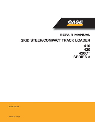
410/420 SKID STEER AND 420CT COMPACT TRACK LOADER
Repair Manual
Mechanical and Pilot Control Machines
(Tier 3 and Cab Up-Grade Machines)
Bur 87634765
Table of Contents (Continued)
Power Train Tab 6
Section Index - Power Train 6-79081
Hydrostatic System”How it Works” (ISO and H-Pattern Pilot Control Machines) 6000 5-4930
Hydrostatic System Troubleshooting 6001 6-79331
Hydrostatic System Troubleshooting (Machines Equipped with Pilot Controls) 6001 5-7610
Removal and Installation of Hydrostatic Components 6002 6-79532
Drive Coupling 6003 6-79120
Drive Coupling - Tier 3 Engines 6003 5-9440
Piston Pump 6004 6-49580
Piston Pump (Machines Equipped with Pilot Controls) 6004 5-7600
Drive Motors (Eaton) 6005 6-79020
Drive Motors -Single Speed 6005 6-79000
Sprocket, Chains, and Axle Assemblies 6007 6-79300
Wheels and Tires 6011 6-79310
Load Management System 6012 5-7590
Brakes Tab 7
Section Index - Brakes 6-79091
Removal and Installation of Park Brake Components 7002 6-79571
410 Brakes - Spring Applied - Hydraulic Release
(Refer to Section 6005 - Single Speed Drive Motor)
420 Brakes - Spring Applied - Hydraulic Release 7004 6-79580
420CT Brakes - Refer to Section 5003 Track Drive Motor
Hydraulics Tab 8
Section Index - Hydraulics 6-79102
Hydraulic System Troubleshooting and Schematics (Mechanical and Pilot
Control Machines)
8001 6-79512
Cleaning the Hydraulic System and Hydrostatic System 8002 6-45290
Removal and Installation of Hydraulic Components 8003 6-79520
Gear Pump (Equipment and High Flow) 8004 6-79350
Loader Control Valve 8005 5-2640
Cylinders 8006 6-79360
Flat Faced Couplers 8007 7-54740
Accumulator for Ride Control 8013 6-45550
Description Section Number
Publication
Form Number
4. Bur 6-78992 Revised 12-07 Printed in U.S.A.
410/420 SKID STEER AND 420CT COMPACT TRACK LOADER
Repair Manual
Mechanical and Pilot Control Machines
(Tier 3 and Cab Up-Grade Machines)
Bur 87634765
Table of Contents (Continued)
Mounted Equipment Tab 9
Section Index - Mounted Equipment 6-79111
Pedals and Levers 9001 6-79500
Pedals and Levers (Cab Up-Grade Machines) 9001 5-7670
Loader 9002 6-79390
Attachment Coupler 9003 6-79400
ROPS Canopy, Seat, Seat Belts, and Operators Compartment 9004 6-79410
ROPS Canopy, Seat, Seat Belts, and Operators Compartment (Cab Up-Grade
Machines)
9004 5-9460
Heater 9006 6-79450
Air Conditioning Troubleshooting for Systems with R134A Refrigerant
(Cab Up-Grade Machines)
9011 5-9480
Air Conditioner System Gauges and Testing for Systems with R134A
Refrigerant (Cab Up-Grade Machines)
9012 5-9490
Refrigerant Recovery, Compressor Removal and System Evacuation
and Recharging (Cab Up-Grade Machines)
9013 5-9500
Air Conditioner System Gauges and Testing for Systems with R134A
Refrigerant (Cab Up-Grade Machines)
9014 5-9510
Schematic Set
Hydraulic and Electrical Schematic Foldout In Rear Pocket 6-78971
Hydraulic and Electrical Schematic Foldout (Tier 3 - Cab Up-Grade and
Machines Equipped with Pilot Controls)
In Rear Pocket 5-9610
Description Section Number
Publication
Form Number
5. Bur 6-78992 Revised 12-07 Printed in U.S.A.
410/420 SKID STEER AND 420CT COMPACT TRACK LOADER
Repair Manual
Mechanical and Pilot Control Machines
(Tier 3 and Cab Up-Grade Machines)
Bur 87634765
Table of Contents (Continued)
NOTES
9. 1001-3
Bur 6-79031 Revised 3-06 Printed in U.S.A.
CAPACITIES AND LUBRICANTS
FUEL TANK
Capacity .................................................................................................................... 83.3 litres (22 U.S. gallons)
Specifications .......................................................................................... See diesel fuel specifications on page 5
COOLING SYSTEM
Capacity ................................................................................................................................17 litres (17.9 quarts)
Recovery bottle capacity .......................................................................................................... 2 litres (2.1 quarts)
Specifications ................................................................................................ 50% water and 50% ethylene glycol
HYDRAULIC SYSTEM
Capacity - Total System .................................................................................................. 50.2 litres (13.3 gallons)
Capacity - Reservoir........................................................................................................... 32.4 litres (7.1 gallons)
Specifications .................................................................................... Case Akcela No. 1 Engine Oil SAE 10W30
CHAIN COMPARTMENTS
Capacity - Each Side ............................................................................................................ 5.7 litres (6.0 quarts)
Specifications ................................................................................... Case Akcela No. 1 Engine Oil, SAE 10W30
FINAL DRIVE (CT MODELS)
Capacity - Each Side .............................................................................................................. 0.55 L (0.58 quarts)
Specifications ....................................................................CASE AKCELA GEAR LUBE SSL 75W-90 (Synthetic)
BATTERY
Quantity .............................................................................................................................................. As required
Specifications ................................................................................................................................. Distilled water
GREASE FITTINGS
Quantity .............................................................................................................................................. As required
Attachments (If equipped) ..................................................................................................... Quantity as required
Specifications .............................................................................................................. Case molydisulfide grease
ENGINE CRANKCASE OIL (410/420 and 420CT MACHINES)
Capacity - with filter change .................................................................................................. 8.7 litres (9.2 quarts)
Capacity - without filter change ................................................................................................ 8.5 litres (9 quarts)
Specifications ..................................................... Case Akcela No. 1 Engine Oil SAE 10W-30 (API service CH-4)
.................................................................................... (See Oil Viscosity/Temperature Ranges Chart on page 4)
ENGINE CRANKCASE OIL (430/440 and 440CT MACHINES)
Capacity - with filter change ................................................................................................. 12 litres (12.7 quarts)
Specifications ..................................................... Case Akcela No. 1 Engine Oil SAE 10W-30 (API service CH-4)
.................................................................................... (See Oil Viscosity/Temperature Ranges Chart on page 4)
ENVIRONMENT
Before you service this machine and dispose of oil, fluids and lubricants, always remember the environment. Do
not put oil or fluids into the ground or into containers that can leak. Check with your local environmental, recycling
center or your Case dealer for correct disposal information.
10. 1001-4
Bur 6-79031 Revised 3-06 Printed in U.S.A.
ENGINE LUBRICATION
Engine Oil Selection
Case Akcela No. 1 Engine Oil is recommended for
use in your Case Engine. Case Akcela Engine Oil will
lubricate your engine correctly under all operating
conditions.
.
See the chart below for recommended viscosity at
ambient temperature ranges.
NOTE: Do not put Performance Additives or other oil
additive products in the engine crankcase. The oil
change intervals given in the operating manual are
according to tests with Case lubricants.
Oil Viscosity/Temperature Ranges
BS99N019
11. 1001-5
Bur 6-79031 Revised 3-06 Printed in U.S.A.
DIESEL FUEL SYSTEM
Use No. 2 diesel fuel in the engine of this machine.
The use of other fuels can cause the loss of engine
power and high fuel consumption.
In very cold temperatures, a mixture of No. 1 and No.
2 diesel fuels is temporarily permitted. See the
following:
NOTE: See your fuel dealer for winter fuel
requirements in your area. If the temperature of the
fuel lowers below the cloud point (wax appearance
point), wax crystals in the fuel will restrict the fuel
filter and cause the engine to loose power or not
start.
The diesel fuel used in this machine must meet the
specifications below, “Specifications for Acceptable
No. 2 Diesel Fuel” or Specification D975-81 of the
American Society for Testing and Materials.
Fuel Storage
If you keep fuel in storage for a period of time, you
can get foreign material or water in the fuel storage
tank. Many engine problems are caused by water in
the fuel.
Keep the fuel storage tank outside and keep the fuel
as cool as possible. Remove water from the storage
container at regular periods of time.
Fill the fuel tank at the end of the daily operating
period to prevent condensation in the fuel tank.
Specifications for Acceptable No. 2 Diesel Fuel
API Gravity, Minimum ............................................................................................................................................ 34
Flash Point, Minimum .......................................................................................................................... 60°C (140° F)
Cloud Point (wax appearance point), Maximum ................................................................................... -20°C (-5° F)
Pour Point, Maximum .......................................................................................................................... -26° C (-15° F)
Distillation Temperature, 90% Point .............................................................................282 to 338°C (540 to 640° F)
Viscosity, at 38° C (100° F)
Centistokes ............................................................................................................................................ 2.0 to 4.3
Saybolt Seconds Universal ...................................................................................................................... 32 to 40
Cetane Number, Minimum .......................................................................... 43 (45 to 55 for winter or high altitudes)
Water and Sediment, by Volume, Maximum .............................................................................................. 0.5 of 1%
Sulphur, by Weight, Maximum .....................................................................................................................0.5 of 1%
Copper Strip Corrosion, Maximum ................................................................................................................... No. 2
Ash, by Weight, Maximum .......................................................................................................................... 0.1 of 1%
14. 1001-3
Bur 5-7580 Issued 12-07 Printed in U.S.A.
CAPACITIES AND LUBRICANTS
FUEL TANK
All Models
Capacity ............................................................................................................. 88.2 litres (23.3 U.S. gallons)
Specifications...................................................................................... See diesel fuel specifications on page 6
COOLING SYSTEM - TIER 3 ENGINES
410 (North American Machines)
Total Capacity.........................................................................................................11.5 litres (12.2 U.S.quarts)
Additional Coolant Required If Equipped with Heater.................................................3.8 litres (4.0 U.S.quarts)
Recovery Bottle Capacity............................................................................................. 1.9 litres (1.0 U.S.quart)
Specifications............................................................................................ 50% water and 50% ethylene glycol
410 (European Machines)
Total Capacity.........................................................................................................11.5 litres (12.2 U.S.quarts)
Additional Coolant Required If Equipped with Heater.................................................3.8 litres (4.0 U.S.quarts)
Recovery Bottle Capacity............................................................................................. 1.9 litres (1.0 U.S.quart)
Specifications............................................................................................ 50% water and 50% ethylene glycol
420/420CT (North American Machines)
Total Capacity..........................................................................................................11.5litres (12.2 U.S.quarts)
Additional Coolant Required If Equipped with Heater.................................................3.8 litres (4.0 U.S.quarts)
Recovery Bottle Capacity............................................................................................. 1.9 litres (1.0 U.S.quart)
Specifications............................................................................................ 50% water and 50% ethylene glycol
420/420CT (European Machines)
Total Capacity.........................................................................................................11.5 litres (12.2 U.S.quarts)
Additional Coolant Required If Equipped with Heater.................................................3.8 litres (4.0 U.S.quarts)
Recovery Bottle Capacity............................................................................................. 1.9 litres (1.0 U.S.quart)
Specifications............................................................................................ 50% water and 50% ethylene glycol
HYDRAULIC SYSTEM
All Models
Capacity - Total System ......................................................................................... 50 litres (13.2 U.S. gallons)
Capacity - Reservoir .............................................................................................. 26.6 litres (7.1 U.S. gallons)
Specifications ................................................................................ Case Akcela No. 1 Engine Oil SAE 10W30
CHAIN COMPARTMENTS
All Models
Capacity - Each Side .................................................................................................3.8 litres (4.0 U.S.quarts)
Specifications ............................................................................... Case Akcela No. 1 Engine Oil, SAE 10W30
FINAL DRIVE
(CT Models Only)
Capacity - Each Side ...................................................................................................... 1.3 L (1.4 U.S.quarts)
Specifications..................................................................................CASE AKCELA GEAR LUBE SSL 80W-90
BATTERY
Quantity .......................................................................................................................................... As required
Specifications ............................................................................................................................. Distilled water
GREASE FITTINGS
Quantity .......................................................................................................................................... As required
Attachments (If equipped)................................................................................................. Quantity as required
Specifications .......................................................................................................... Case molydisulfide grease
ENGINE CRANKCASE OIL - TIER 3 ENGINES
410 (North American and European Machines)
Capacity - with filter change.................................................................................. 10.5 litres (11.1 U.S.quarts))
Capacity - without filter change............................................................................... 9.9 litres (10.5 U.S.quarts))
Specifications................................................. Case Akcela No. 1 Engine Oil SAE 10W-30 (API service CH-4)
................................................................................ (See Oil Viscosity/Temperature Ranges Chart on page 5)
15. 1001-4
Bur 5-7580 Issued 12-07 Printed in U.S.A.
ENGINE CRANKCASE OIL - TIER 3 ENGINES
420 and 420CT (North American and European Machines)
Capacity - with filter change......................................................................................... 8.5 litres (9 U.S.quarts))
Capacity - without filter change.................................................................................... 8.0 litres (8 U.S.quarts))
Specifications................................................. Case Akcela No. 1 Engine Oil SAE 15W-40 (API service CH-4)
................................................................................ (See Oil Viscosity/Temperature Ranges Chart on page 5)
ENVIRONMENT
Before you service this machine and dispose of oil, fluids and lubricants, always remember the environment. Do
not put oil or fluids into the ground or into containers that can leak. Check with your local environmental, recycling
center or your Case dealer for correct disposal information.
18. 2000-3
Bur 5-7650 Issued 12-07 Printed in U.S.A.
RADIATOR
Removal
NOTE: Put caps on all fittings and plugs in all
disconnected hoses.
STEP 1
Park the machine on a level surface.
STEP 2
Lift the hood and open the rear access door on the
machine.
STEP 3
Turn the ignition switch and the master disconnect
switch (if equipped) to the OFF position.
STEP 4
Disconnect the negative battery cable from the
battery.
STEP 5
BD07K011-01
Slowly loosen the radiator cap (15). Disconnect the
overflow hose (5) from the radiator neck.
NOTE: Refer to illustration on page 5.
STEP 6
BD07M176-01
If equipped with a heater, open the heater coolant
valve.
STEP 7
BD07K006-01
Install a hose on the drain valve (1) and drain the
radiator into a clean container that holds
approximately 17 litres (4.5 gallons).
STEP 8
BD07M176-01
If equipped with a heater, close the heater coolant
valve (1).
5
15
1
1
1
19. 2000-4
Bur 5-7650 Issued 12-07 Printed in U.S.A.
STEP 9
BD07K011-01
Loosen the clamp (1) on the upper radiator hose and
remove the hose from the upper radiator connection.
STEP 10
BD07K006-01
Loosen and remove the top (1) and bottom (2)
mounting bolts on the radiator and oil cooler module.
Use acceptable lifting equipment to support the
radiator and oil cooler module after removal of the
mounting bolts. Pull the radiator and oil cooler
module away from the fan shroud until you can
access the lower radiator hose clamp.
STEP 11
BD07K006-01
Loosen the clamp (4) on the lower radiator hose and
remove the hose from the lower radiator connection.
NOTE: Refer to illustration on page 5.
STEP 12
BD07K006-01
Remove the cap (1) from the hydraulic reservoir.
Connect a vacuum pump to the hydraulic reservoir.
Start the vacuum pump.
STEP 13
BD07K006-01
Loosen and remove the upper (1) and lower (2)
hoses from the oil cooler (3). Install plugs in the
hoses and caps on the fittings to prevent loss of
hydraulic oil from the hydraulic system. Stop the
vacuum pump.
STEP 14
BD07K006-01
Remove the radiator and oil cooler module from the
machine.
1
1
2
1
2
4
1
1
3
2
1
21. 2000-6
Bur 5-7650 Issued 12-07 Printed in U.S.A.
Installation
STEP 15
Installation of the radiator is the reverse procedure of
removal.
STEP 16
After the radiator has been installed, fill the cooling
system. See Section 1001 for the correct coolant
mixture and quantity.
STEP 17
Start and run the engine until it reaches operating
temperature and check for any leaks. Stop the
engine. After the engine has cooled, check the level
of the cooling system and add coolant as required.
22. 2000-7
Bur 5-7650 Issued 12-07 Printed in U.S.A.
ENGINE
Removal
STEP 1
Remove the radiator from the machine.
STEP 2
Install plugs and caps on all disconnected hoses and
fittings.
STEP 3
Tag all electrical connection for identification during
assembly.
STEP 4
BD05B048
If equipped with a heater, disconnect the heater
hoses (1) from the engine.
STEP 5
Lift the rear hood and open the rear access door.
STEP 6
BD07M168-01
Disconnect the electrical connectors from the rear tail
lamps (1) on both sides of the rear access door.
Disconnect the electrical connectors from the rear
worklight (2). Disconnect the electrical connectors
from the backup alarm (3). Remove mounting
hardware from the wiring harness (4) and remove the
harness (4) from the rear access door.
STEP 7
BD07M168-01
Connect acceptable lifting equipment to the rear
access door. Remove the pivot bolt (1) and lift the
rear access door and remove from the machine.
1
1
132
1
23. 2000-8
Bur 5-7650 Issued 12-07 Printed in U.S.A.
STEP 8
BD07K006-01
1. CYLINDER PIVOT BOLT
Remove the nut from cylinder pivot bolt (1) on the
hood end of the cylinder.
STEP 9
BD07K006-01
Remove the plastic clip (2) from the hood pivot shaft.
Slide the hood to the left and remove the hood from
the hood pivot shaft on both sides of the machine.
Remove the hood from the machine.
STEP 10
Push the hood to the right hand side of the machine
and remove the left hand side of the hood from the
pivot pin. Remove the hood from the machine.
STEP 11
BD07K060-01
Loosen the clamp (1) on the outlet hose (2). Remove
the outlet hose (2) from the intake and air filter
assembly (3).
NOTE: Torque clamps (1) 3 to 4 Nm (25 to 35
pound-inches) during assembly.
STEP 12
Loosen and remove the mounting bolts and washers
from the air filter housing mounting bracket.
STEP 13
Remove the air cleaner and bracket from the
machine.
STEP 14
Remove the bolts and washers that fasten the front
muffler support rods (5 and 8) and the rear muffler
support rods (14 and 16) to the engine.
NOTE: Torque bolts 23 to 26 Nm (204 to 228
pound-inches) during assembly.
STEP 15
Loosen and remove the bolts and washers that
fasten the muffler to the exhaust manifold.
NOTE: Torque the bolts 51 to 61 Nm (38 to 45
pound-feet) during assembly.
STEP 16
Remove the muffler from the engine.
STEP 17
Remove the cap screws (7), washers (8), fan blade
(1), from the engine. Loosen and remove cap screws
(4), washers (3) and spacer (2) from the engine.
1
2
2
3
1
24. Thank you very much for
your reading. Please Click
Here. Then Get COMPLETE
MANUAL. NO WAITING
NOTE:
If there is no response to
click on the link above,
please download the PDF
document first and then
click on it.
25. 2000-9
Bur 5-7650 Issued 12-07 Printed in U.S.A.
STEP 18
BD07M186-01
1. STARTER WIRES
2. WIRE HARNESS CLAMP
Disconnect the wires (1) from the starter and from
the alternator (2). Loosen and remove the bolts and
wire harness clamp (2) from the engine.
STEP 19
Loosen and remove the bolts that fastens the ground
wires to the engine. Keep all ground wires together.
STEP 20
BD07M169-01
1. ALTERNATOR WIRES
Disconnect the wires from the alternator.
STEP 21
BD07M172-01
Remove the throttle linkage (1) from the fuel injection
pump and the linkage (2) to the throttle control lever.
STEP 22
Disconnect the wire for the engine coolant
temperature switch and the engine oil pressure
switch.
STEP 23
BD07M173-01
Disconnect the wire connector for the fuel injection
pump solenoid.
STEP 24
Loosen and remove the bolts that fasten the wire
harness to the right side of the machine.
STEP 25
Move the all of the wiring harness out of the way.
1
2
1
1
2
26. 2000-10
Bur 5-7650 Issued 12-07 Printed in U.S.A.
STEP 26
BD07M175-01
Close the fuel shut off valve.
STEP 27
BD07M171-01
Disconnect the fuel lines (1) from the engine.
Remove the bolts from the clamps (2) and remove
the fuel lines (1) from the engine.
STEP 28
BD07M172-01
Loosen and remove the mounting bolts (1) which
fasten the throttle linkage assembly (2) to the engine.
Remove the linkage assembly (2) from the engine.
Loosen and remove the mounting bolts (3) which
fasten the cover (4) to the engine. Remove the cover
(4).
STEP 29
BD07M172-01
Loosen and remove the mounting bolts (1) which
fasten the pump drive joint (2) to the flywheel (3).
Remove the pump drive joint (2) from the flywheel
(3).
NOTE: Tighten pump drive joint bolts to a torque of
94 to 106 Nm (68 to 78 pound-feet) during assembly.
1
2
1
1
3
2
4
1
3
2
27. 2000-11
Bur 5-7650 Issued 12-07 Printed in U.S.A.
STEP 30
BD07M171-01
Connect acceptable lifting equipment to the engine
lifting eyes at the front and rear of the engine.
STEP 31
Remove the bolt, washers, and nut from the rear
engine mount (2).
NOTE: Torque the bolts 110 to 122 Nm (80 to 90
pound-feet) during assembly.
STEP 32
Remove the bolts, washers, and nut from the front
engine mounts (1).
NOTE: Torque the bolts 110 to 122 Nm (80 to 90
pound-feet) during assembly.
NOTE: Refer to illustration on page 13.
STEP 33
Use lifting equipment and remove the engine from
the chassis.
NOTE: During assembly apply Molykote GN to the
pump drive joint splines before assembly.
Installation
STEP 34
Installation of the engine is the reverse procedure of
removal.
STEP 35
After the engine and radiator have been installed,
refill the engine cooling system. Refill the engine
crankcase with engine oil. See Section 1001 for the
correct type and quantity of engine coolant and
engine oil.
STEP 36
Start and run the engine at low idle until the engine
reaches operating temperature and check for any
leaks. Stop the engine. After the engine has cooled,
check the level of the coolant in the cooling system.
Add coolant as required. Check the oil level in the
engine crankcase. Add engine oil as required.
28. 2000-12
Bur 5-7650 Issued 12-07 Printed in U.S.A.
BS07K678
1. FRONT ENGINE MOUNT
2. REAR ENGINE MOUNT
3. FRONT ISO MOUNTS
4. REAR ISO MOUNT
5. FRONT MOUNTING BOLTS
6. FRONT MOUNTING PLATE NUT
7. REAR MOUNTING BOLT
8. LARGE MOUNTING WASHERS
9. WASHER
10. CAP SCREW
11. NUT
12. WASHER
13. CAP SCREW
14. PUMP DRIVE JOINT
410 ENGINE MOUNTING
1
1
2
14
3
8
6
5
8
3
8
6
5
8
11
8
4
9
7
10
9
9
13
12
13
12
29. 2000-13
Bur 5-7650 Issued 12-07 Printed in U.S.A.
BS07K857
1. AIR CLEANER BODY
2. PRIMARY FILTER ELEMENT
3. SECONDARY FILTER ELEMENT
4. COVER
5. AIR CLEANER INLET HOSE
6. DUST VALVE
7. CLAMP
8. CAP SCREW
9. WASHER
10. AIR CLEANER INLET HOSE
11. AIR CLEANER INLET COUPLER
12. AIR CLEANER MOUNTING BRACKET
13. PLASTIC PLUG
410 AIR FILTER ASSEMBLY
1
4
2
3
7
7
7
10
11
5
12
8
9
13
6