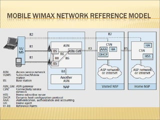
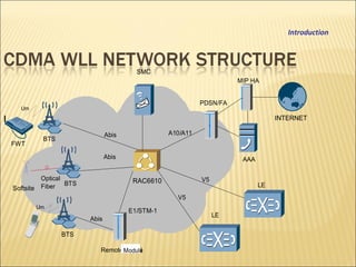
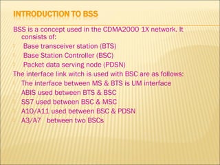
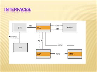
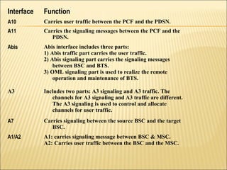
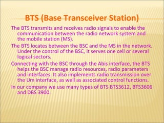
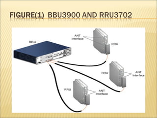
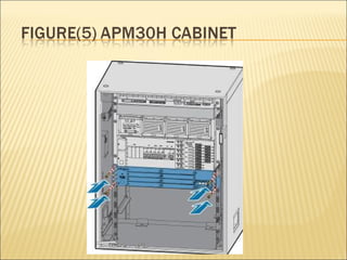
BSS course
 CDMA overviewCDMA overview
 WiMAX overviewWiMAX overview
 BSCBSC
 BTSBTS
 CDMA overviewCDMA overview
 WiMAX overviewWiMAX overview
 BSCBSC
 BTSBTS
1st
Generation
1980s (analog)
2nd
Generation 1990s
(digital)
3rd
Generation
current (digital)
3G provides:
 Complete integrated service solutions
 High bandwidth
AMPS
Analog to Digital
TACS
OTHERS
GSM
CDMA
IS95
TDMA
IS-136
UMTS
WCDMA
CDMA
2000
TD-
SCDMA
Voice to Broadband
Traffic channels: different users
are assigned unique code and
transmitted over the same
frequency band, for example,
WCDMA and CDMA2000
Traffic channels: different frequency bands are
allocated to different users,for example, AMPS
and TACS
Traffic channels: different time slots are
allocated to different users, for example,
DAMPS and GSM
Frequency
Time
Power
Frequency
Time
Power
Frequency
Time
Power
FDMA
TDMA
CDMA
User
User
User
User
User
User
CDMA2000 1X
Code-Division Multiple Access, a digital cellular technology
that uses spread-spectrum techniques. Unlike competing
systems, such as GSM, that use TDMA, CDMA does not
assign a specific frequency to each user. Instead, every
channel uses the full available spectrum. Individual
conversations are encoded with a pseudo-random digital
sequence. CDMA consistently provides better capacity for
voice and data communications than other commercial
mobile technologies, allowing more subscribers to connect
at any given time, and it is the common platform on which
3G technologies are built.
IS95A
9.6kbps
IS95A
115.2kbps
CDMA2000 307.2kbps
 Heavier voice
service capacity ;
 Longer period of
standby time
CDMA2000
3X
CDMA2000 1X
EV
1X EV-DO
1X EV-DV
1995 1998
2000
2003
 Higher spectrum efficiency and network capacity
 Higher packet data rate and more diversified services
 Smooth transit to 3G
Introduction
InterleavingSource
coding
Convolution
&
Interleaving
Scrambling Spreading Modulation
RF
transmission
Source
decoding
deinterleavingDecovolution
&
Deinterleaving
Unscrambling De-spreading Demodulation RF receiving
 Bit, Symbol, Chip:
 A bit is the input data which contain information
 A symbol is the output of the convolution, encoder,
and the block interleaving
 A chip is the output of spreading
 Processing Gain:
 Processing gain is the ratio of chip rate to the bit
rate.
 The processing gain in IS-95 system is 128, about
21dB.
 Forward direction: Information path from base station to
mobile station
 Reverse direction: Information path from mobile station
to base station
BTS
Power Control Bit
Eb/Nt Value FER Value
Inner Loop Power Control
Outer Loop Power Control
Change in Eb/Nt Value
BSC
BTS
Soft handoff
It is a process of establishing a link with a target sector before breaking the link
with the serving sector
Softer handoff
Like the soft handoff, but the handoff is occurred between multi-sectors in the
same base station
Hard handoff
Hard handoff occurs when the two sectors are not synchronized or are not on the
same frequency. Interruption in voice or data communication occurs but this
interruption does not effect the user communication
RAKE antennas help to overcome on the multi-path fading and enhance the
receive performance of the system
Receive set
Correlator 1
Correlator 2
Correlator 3
Searcher correlator
Calculate the time
delay and signal
strength
Combiner The combined
signal
tt
s(t) s(t)
 CDMA overviewCDMA overview
 WiMAX overviewWiMAX overview
 BSCBSC
 BTSBTS
 WiMAX (worldwide interoperability for microwave access)
is the commercial name for products based on the IEEE
802.16 standard as trade marked by the WiMAX Forum,
an association of companies representing the ecosystem
of the WiMAX technology.
 There are two commercial versions of WiMAX:
1. Fixed WiMAX based on IEEE 802.16d (or 802.16-2004,
approved in June 2004) and
2. Mobile WiMAX based on IEEE 802.16e-2005 (ratified in
December 2005). Mobile WiMAX can be used in both fixed and
mobile scenarios while Fixed WiMAX does not support mobility
features.
 WiMAX is generally considered a(4G) wireless access
technology that provides significant advancement in
throughput over existing wireless access technologies.
 These advancements are made possible because WiMAX
implements the following technologies which are common with
other 4G wireless access systems (most notably Long Term
Evolution – LTE):
1. Orthogonal Frequency Division Multiple Access (OFDMA)
2. Advanced Antenna Systems: Multiple Input Multiple Output (MIMO)
techniques
3. Flat-IP Architecture
 Reduces the total cost of ownership of the network
 reduces the deployment cycle to allow for faster time-to-operation of
the network.
 The Network Working Group (NWG) of the WiMAX Forum has
developed the Network Reference Model (NRM) which
identifies the functional entities and reference points over
which interoperability is achieved between the functional
entities. The NRM is divided into three functional entities:
1. The mobile station (MS).
2. The Access Service Network (ASN): includes the set of functions
allowing a WiMAX subscriber access to the radio network.
3. The Connectivity Service Network (CSN): is defined as the set of
network functions that provide IP connectivity services to a WiMAX
subscriber.
 CDMA overviewCDMA overview
 WiMAX overviewWiMAX overview
 BSCBSC
 BTSBTS
LE
MIP HA
AAA
PDSN/FA
Abis
BTS
A10/A11
Um
V5
LE
V5Optical
FiberSoftsite
Um
Remote Model
Abis
E1/STM-1
Module
RAC6610
BTS
BTS
SMC
Abis
FWT
INTERNET
Introduction
BSS is a concept used in the CDMA2000 1X network. It
consists of:
 Base transceiver station (BTS)
 Base Station Controller (BSC)
 Packet data serving node (PDSN)
The interface link witch is used with BSC are as follows:
 The interface between MS & BTS is UM interface
 ABIS used between BTS & BSC
 SS7 used between BSC & MSC
 A10/A11 used between BSC & PDSN
 A3/A7 between two BSCs
 The Airbridge BSC6600 Base Station Controller is a
solution based on CDMA system. It provides the
functions of BTS control, radio resource management,
call control, mobility management, and intra-local-
network roaming. It realizes the services of voice, fax,
packet data and short message.
 The BSC6600 supports the large-capacity and small-
capacity configuration schemes.
 In Fanoos Telecom we use two Frequency
Bands
 Band Class 1: 1,900MHz band
 Band Class 5: 450 MHz band
To MSC ( SS7
interface)
 The BAM enables users to implement the
O&M and management of the system,
including managing and maintaining the
configuration data, performance
measurement data, alarm information, etc.
 The BSC6600 provides effective O&M
methods and tools to guarantee the normal
operation of the system, to lower the
operation cost, and to improve the
communication service quality.
 The CSWS is responsible
for:
 Providing central switching
functions;
 Providing channels for
information exchange
between service subracks;
 Providing Maintenance and
management channel for
various processing subracks.
 In small-capacity
configuration we don’t use
CSWS.
CLPC
CLPC
CNET
Other subracksOther subracks
BAMBAMCMPU
 CRPS is responsible for:
 BSC system resource
management
 Provision of periodic
synchronization cell for
other CIPSs
 Transfer of packet data
service
 Buffering Provide periodical
time synchronization
Packet data
service processing
Provide A3/A7
physical interface
From CIPSFrom CIPS
From original
CIPS
From original
CIPS
To CIPSTo CIPS
From CLKMFrom CLKM
To PDSNTo PDSN
To target CIPSTo target CIPS
Resource
management
This subrack performs such functions as frame selection for
services, data distribution, signaling control, encoding and
decoding of speech and Echo Cancellation (EC).
A1/A2 physical
interface
Abis
Physical
interface
Signaling control
Speech encoding
and decoding.
Service
frame
selection,
data
allocation
To CRPSTo CRPS
To MSCTo MSCAbis OMLAbis OML
Abis signalingAbis signaling
Abis trafficAbis traffic
 Capacity of BSC depends on CIPS subrack, the
capacity of each CIPS is 12500 subscribers,
 For small-capacity configuration we have 4
CIPS, for large-capacity configuration is above 4
CIPS.
 The maximum number of CIPS is 11 in one BSC
(for Full configuration).
Air interface
Abis
BSC
BSC
A1/A2
A1/A2 MSC
Interface Function
A10 Carries user traffic between the PCF and the PDSN.
A11 Carries the signaling messages between the PCF and the
PDSN.
Abis Abis interface includes three parts:
1) Abis traffic part carries the user traffic.
2) Abis signaling part carries the signaling messages
between BSC and BTS.
3) OML signaling part is used to realize the remote
operation and maintenance of BTS.
A3 Includes two parts: A3 signaling and A3 traffic. The
channels for A3 signaling and A3 traffic are different.
The A3 signaling is used to control and allocate
channels for user traffic.
A7 Carries signaling between the source BSC and the target
BSC.
A1/A2 A1: carries signaling message between BSC & MSC.
A2: Carries user traffic between the BSC and the MSC.
 CDMA overviewCDMA overview
 WiMAX overviewWiMAX overview
 BSCBSC
 BTSBTS
BTS (Base Transceiver Station)
The BTS transmits and receives radio signals to enable the
communication between the radio network system and
the mobile station (MS).
The BTS locates between the BSC and the MS in the network.
Under the control of the BSC, it serves one cell or several
logical sectors.
Connecting with the BSC through the Abis interface, the BTS
helps the BSC manage radio resources, radio parameters
and interfaces. It also implements radio transmission over
the Um interface, as well as associated control functions.
In our company we use many types of BTS BTS3612, BTS3606
and DBS 3900.
 Each BTS is contains 3 sectors
 If we configure the BTS S111 ( 3 sectors with 1
carrier ), the capacity is 1200 subscribers.
 If we configure the BTS S333 ( 3 sectors with 3
carriers ), the capacity is 3600 subscribers.
 We can configure BTS ( S222, S33 … ), these
configures depend on our plan.
Cabinet Physical Features
 The dimensions of the cabinet are
(excluding the components on the top
of the cabinet): 1,800 mm x 800 mm x
650 mm (height x width x depth)
The BTS3612 cabinet features:
 Light weight to its aluminum alloy
materials
 Excellent electrical conductivity and
shielding effect
 Good ventilation effect to its
reasonable design of air ducts
 Easy installation and maintenance
 Nice and attractive outlook
 The BTS3612 cabinet
is composed of:
 Baseband subrack
 Fan box
 Power supply subrack
 Carrier subrack,
 RLDU subrack
 CDU/DDU subrack
RF subrack
CDU/RLDU subrack
Fan subrack
Baseband subrack
RF subrack
Power subrack
The baseband subrack is installed at the upper part of
the BTS3612 cabinet. It can be configured with
baseband subsystem boards.
The baseband subsystem performs the following
functions:
 Abis interface protocol processing.
 Baseband data modulating/demodulating.
 Channel encoding/decoding.
 Air interface physical layer.
 Clock synchronization processing.
 System operation and maintenance.
The RF subrack is responsible of providing
service for subscriber.
There are some operations done in RF
subracks like modulation, amplification,
and filtration.
 The RF antenna is used
to transmit and receive
the radio signals for MS
 The RF antenna system
of the BTS is composed
of antenna, jumper
from antenna to feeder,
feeder, and the jumper
from feeder to the
bottom of the cabinet.
 Many important features of the CDMA network
are closely related to and much dependent on
the global satellite navigation system. If the
global satellite navigation system stops working
for a long time, the whole CDMA network will
collapse.
 To ensure the system security and reliability,
the BTS receives signals of the GPS system
through a satellite synchronization antenna
system to implement radio synchronization.
 A satellite synchronization antenna system is
composed of an antenna, the jumper from
antenna to feeder, feeders, a lightning arrester
and the jumper from feeder to cabinet-bottom
(the feeders and jumpers can be configured as
needed). Figure below shows the structure
 The DBS3900 is consisting of functional
modules (such as BBU3900 and RRU3702)
and auxiliary devices (such as APM ).
 The BBU3900 and RRU3702 are connected
through the optical fiber,
 Baseband unit: BBU3900
 The BBU3900 is a baseband unit that
processes baseband signals.
 The dimensions of the BBU3900 are: 442 mm x
310 mm x 86 mm (width x depth x height).
 Remote RF unit: RRU3702
 The RRU3702 is an outdoor remote RF unit that
receives and transmits RF signals, and then
processes and transmits them to the BBU3900
or RF antenna.
 Provides the port for data communications between
the BBU3900 and the ASN-GW
 Provides the maintenance channel to the M2000
 Provides the CPRI port for communications between
the BBU3900 and the RRU3702
 Processes uplink and downlink baseband signals.
 Manages the entire DBS3900 system, including OM
and signaling processing
 Provides the system clock port
 Provides the alarm monitoring port
 It receives RF signals from the antenna system, down-converts the
RF signals to intermediate frequency (IF) signals, performs
amplification, analog-to-digital conversion, digital down-
conversion, matched filtering, and Digital Automatic Gain Control
(DAGC) for the IF signals, and then transmits them to the BBU.
 Receives the downlink baseband digital signals from the upper-
level equipment (baseband module), performs matched filtering,
digital up-conversion, and clipping for the signals, modulates the
output IQ signals to qualified transmit signals, amplifies the
signals, and transmits them through antennas.
 The RRU3702 supports the 4T4R technology (four transmit
channels and four receive channels). Each channel supports a
maximum of two carriers and 20 MHz working bandwidth.
 Installation Position
 One end of the CPRI
optical fiber is connected
to the CPRI0, CPRI1, or
CPRI2 port on the BBBI of
the BBU3900, and the
other end is connected to
the CPRI0 port or CPRI1
port on the RRU3702 .
Before connecting an
optical fiber to a CPRI
port, you need to install a
removable optical module
to the port.
 APM (Advanced Power Module)
 The APM is an integrated outdoor power backup
system.
 The APM performs the following functions:
 Provides built-in batteries and 220 V AC surge protection
module
 Supplies a maximum of -48 V DC 60 A power
 Provides the space for the installation of customer
devices
 Provides remote communication alarms
 Provides multiple circuits of DC distribution outputs
 BAM : Back Administration Module
 CSWS: CDMA SWitching Subrack
 CRPS: CDMA Resource & Packed Subrack
 CIPS: CDMA Integrated Processing Subrack
 CMPU: CDMA Main Processing Unit
 CNET: CDMA NETwork transfer and switching unit
 CLPC: CDMA Line Processing Card
 GSM : Global System for Mobile communication
 GPS: Global Positioning System
Thank you

BSS training 2012 - for students

  • 1.
  • 2.
     CDMA overviewCDMAoverview  WiMAX overviewWiMAX overview  BSCBSC  BTSBTS
  • 3.
     CDMA overviewCDMAoverview  WiMAX overviewWiMAX overview  BSCBSC  BTSBTS
  • 4.
    1st Generation 1980s (analog) 2nd Generation 1990s (digital) 3rd Generation current(digital) 3G provides:  Complete integrated service solutions  High bandwidth AMPS Analog to Digital TACS OTHERS GSM CDMA IS95 TDMA IS-136 UMTS WCDMA CDMA 2000 TD- SCDMA Voice to Broadband
  • 5.
    Traffic channels: differentusers are assigned unique code and transmitted over the same frequency band, for example, WCDMA and CDMA2000 Traffic channels: different frequency bands are allocated to different users,for example, AMPS and TACS Traffic channels: different time slots are allocated to different users, for example, DAMPS and GSM Frequency Time Power Frequency Time Power Frequency Time Power FDMA TDMA CDMA User User User User User User
  • 6.
    CDMA2000 1X Code-Division MultipleAccess, a digital cellular technology that uses spread-spectrum techniques. Unlike competing systems, such as GSM, that use TDMA, CDMA does not assign a specific frequency to each user. Instead, every channel uses the full available spectrum. Individual conversations are encoded with a pseudo-random digital sequence. CDMA consistently provides better capacity for voice and data communications than other commercial mobile technologies, allowing more subscribers to connect at any given time, and it is the common platform on which 3G technologies are built.
  • 7.
    IS95A 9.6kbps IS95A 115.2kbps CDMA2000 307.2kbps  Heaviervoice service capacity ;  Longer period of standby time CDMA2000 3X CDMA2000 1X EV 1X EV-DO 1X EV-DV 1995 1998 2000 2003  Higher spectrum efficiency and network capacity  Higher packet data rate and more diversified services  Smooth transit to 3G Introduction
  • 8.
  • 9.
     Bit, Symbol,Chip:  A bit is the input data which contain information  A symbol is the output of the convolution, encoder, and the block interleaving  A chip is the output of spreading  Processing Gain:  Processing gain is the ratio of chip rate to the bit rate.  The processing gain in IS-95 system is 128, about 21dB.  Forward direction: Information path from base station to mobile station  Reverse direction: Information path from mobile station to base station
  • 10.
    BTS Power Control Bit Eb/NtValue FER Value Inner Loop Power Control Outer Loop Power Control Change in Eb/Nt Value BSC BTS
  • 11.
    Soft handoff It isa process of establishing a link with a target sector before breaking the link with the serving sector Softer handoff Like the soft handoff, but the handoff is occurred between multi-sectors in the same base station Hard handoff Hard handoff occurs when the two sectors are not synchronized or are not on the same frequency. Interruption in voice or data communication occurs but this interruption does not effect the user communication
  • 12.
    RAKE antennas helpto overcome on the multi-path fading and enhance the receive performance of the system Receive set Correlator 1 Correlator 2 Correlator 3 Searcher correlator Calculate the time delay and signal strength Combiner The combined signal tt s(t) s(t)
  • 13.
     CDMA overviewCDMAoverview  WiMAX overviewWiMAX overview  BSCBSC  BTSBTS
  • 14.
     WiMAX (worldwideinteroperability for microwave access) is the commercial name for products based on the IEEE 802.16 standard as trade marked by the WiMAX Forum, an association of companies representing the ecosystem of the WiMAX technology.  There are two commercial versions of WiMAX: 1. Fixed WiMAX based on IEEE 802.16d (or 802.16-2004, approved in June 2004) and 2. Mobile WiMAX based on IEEE 802.16e-2005 (ratified in December 2005). Mobile WiMAX can be used in both fixed and mobile scenarios while Fixed WiMAX does not support mobility features.
  • 15.
     WiMAX isgenerally considered a(4G) wireless access technology that provides significant advancement in throughput over existing wireless access technologies.  These advancements are made possible because WiMAX implements the following technologies which are common with other 4G wireless access systems (most notably Long Term Evolution – LTE): 1. Orthogonal Frequency Division Multiple Access (OFDMA) 2. Advanced Antenna Systems: Multiple Input Multiple Output (MIMO) techniques 3. Flat-IP Architecture  Reduces the total cost of ownership of the network  reduces the deployment cycle to allow for faster time-to-operation of the network.
  • 16.
     The NetworkWorking Group (NWG) of the WiMAX Forum has developed the Network Reference Model (NRM) which identifies the functional entities and reference points over which interoperability is achieved between the functional entities. The NRM is divided into three functional entities: 1. The mobile station (MS). 2. The Access Service Network (ASN): includes the set of functions allowing a WiMAX subscriber access to the radio network. 3. The Connectivity Service Network (CSN): is defined as the set of network functions that provide IP connectivity services to a WiMAX subscriber.
  • 18.
     CDMA overviewCDMAoverview  WiMAX overviewWiMAX overview  BSCBSC  BTSBTS
  • 19.
  • 20.
    BSS is aconcept used in the CDMA2000 1X network. It consists of:  Base transceiver station (BTS)  Base Station Controller (BSC)  Packet data serving node (PDSN) The interface link witch is used with BSC are as follows:  The interface between MS & BTS is UM interface  ABIS used between BTS & BSC  SS7 used between BSC & MSC  A10/A11 used between BSC & PDSN  A3/A7 between two BSCs
  • 21.
     The AirbridgeBSC6600 Base Station Controller is a solution based on CDMA system. It provides the functions of BTS control, radio resource management, call control, mobility management, and intra-local- network roaming. It realizes the services of voice, fax, packet data and short message.  The BSC6600 supports the large-capacity and small- capacity configuration schemes.
  • 22.
     In FanoosTelecom we use two Frequency Bands  Band Class 1: 1,900MHz band  Band Class 5: 450 MHz band
  • 23.
    To MSC (SS7 interface)
  • 24.
     The BAMenables users to implement the O&M and management of the system, including managing and maintaining the configuration data, performance measurement data, alarm information, etc.  The BSC6600 provides effective O&M methods and tools to guarantee the normal operation of the system, to lower the operation cost, and to improve the communication service quality.
  • 26.
     The CSWSis responsible for:  Providing central switching functions;  Providing channels for information exchange between service subracks;  Providing Maintenance and management channel for various processing subracks.  In small-capacity configuration we don’t use CSWS. CLPC CLPC CNET Other subracksOther subracks Other subracksOther subracks BAMBAMCMPU
  • 27.
     CRPS isresponsible for:  BSC system resource management  Provision of periodic synchronization cell for other CIPSs  Transfer of packet data service  Buffering Provide periodical time synchronization Packet data service processing Provide A3/A7 physical interface From CIPSFrom CIPS From original CIPS From original CIPS To CIPSTo CIPS From CLKMFrom CLKM To PDSNTo PDSN To target CIPSTo target CIPS Resource management
  • 28.
    This subrack performssuch functions as frame selection for services, data distribution, signaling control, encoding and decoding of speech and Echo Cancellation (EC). A1/A2 physical interface Abis Physical interface Signaling control Speech encoding and decoding. Service frame selection, data allocation To CRPSTo CRPS To MSCTo MSCAbis OMLAbis OML Abis signalingAbis signaling Abis trafficAbis traffic
  • 29.
     Capacity ofBSC depends on CIPS subrack, the capacity of each CIPS is 12500 subscribers,  For small-capacity configuration we have 4 CIPS, for large-capacity configuration is above 4 CIPS.  The maximum number of CIPS is 11 in one BSC (for Full configuration).
  • 30.
  • 31.
    Interface Function A10 Carriesuser traffic between the PCF and the PDSN. A11 Carries the signaling messages between the PCF and the PDSN. Abis Abis interface includes three parts: 1) Abis traffic part carries the user traffic. 2) Abis signaling part carries the signaling messages between BSC and BTS. 3) OML signaling part is used to realize the remote operation and maintenance of BTS. A3 Includes two parts: A3 signaling and A3 traffic. The channels for A3 signaling and A3 traffic are different. The A3 signaling is used to control and allocate channels for user traffic. A7 Carries signaling between the source BSC and the target BSC. A1/A2 A1: carries signaling message between BSC & MSC. A2: Carries user traffic between the BSC and the MSC.
  • 32.
     CDMA overviewCDMAoverview  WiMAX overviewWiMAX overview  BSCBSC  BTSBTS
  • 33.
    BTS (Base TransceiverStation) The BTS transmits and receives radio signals to enable the communication between the radio network system and the mobile station (MS). The BTS locates between the BSC and the MS in the network. Under the control of the BSC, it serves one cell or several logical sectors. Connecting with the BSC through the Abis interface, the BTS helps the BSC manage radio resources, radio parameters and interfaces. It also implements radio transmission over the Um interface, as well as associated control functions. In our company we use many types of BTS BTS3612, BTS3606 and DBS 3900.
  • 34.
     Each BTSis contains 3 sectors  If we configure the BTS S111 ( 3 sectors with 1 carrier ), the capacity is 1200 subscribers.  If we configure the BTS S333 ( 3 sectors with 3 carriers ), the capacity is 3600 subscribers.  We can configure BTS ( S222, S33 … ), these configures depend on our plan.
  • 35.
    Cabinet Physical Features The dimensions of the cabinet are (excluding the components on the top of the cabinet): 1,800 mm x 800 mm x 650 mm (height x width x depth) The BTS3612 cabinet features:  Light weight to its aluminum alloy materials  Excellent electrical conductivity and shielding effect  Good ventilation effect to its reasonable design of air ducts  Easy installation and maintenance  Nice and attractive outlook
  • 36.
     The BTS3612cabinet is composed of:  Baseband subrack  Fan box  Power supply subrack  Carrier subrack,  RLDU subrack  CDU/DDU subrack RF subrack CDU/RLDU subrack Fan subrack Baseband subrack RF subrack Power subrack
  • 37.
    The baseband subrackis installed at the upper part of the BTS3612 cabinet. It can be configured with baseband subsystem boards. The baseband subsystem performs the following functions:  Abis interface protocol processing.  Baseband data modulating/demodulating.  Channel encoding/decoding.  Air interface physical layer.  Clock synchronization processing.  System operation and maintenance.
  • 38.
    The RF subrackis responsible of providing service for subscriber. There are some operations done in RF subracks like modulation, amplification, and filtration.
  • 39.
     The RFantenna is used to transmit and receive the radio signals for MS  The RF antenna system of the BTS is composed of antenna, jumper from antenna to feeder, feeder, and the jumper from feeder to the bottom of the cabinet.
  • 40.
     Many importantfeatures of the CDMA network are closely related to and much dependent on the global satellite navigation system. If the global satellite navigation system stops working for a long time, the whole CDMA network will collapse.  To ensure the system security and reliability, the BTS receives signals of the GPS system through a satellite synchronization antenna system to implement radio synchronization.  A satellite synchronization antenna system is composed of an antenna, the jumper from antenna to feeder, feeders, a lightning arrester and the jumper from feeder to cabinet-bottom (the feeders and jumpers can be configured as needed). Figure below shows the structure
  • 41.
     The DBS3900is consisting of functional modules (such as BBU3900 and RRU3702) and auxiliary devices (such as APM ).  The BBU3900 and RRU3702 are connected through the optical fiber,
  • 43.
     Baseband unit:BBU3900  The BBU3900 is a baseband unit that processes baseband signals.  The dimensions of the BBU3900 are: 442 mm x 310 mm x 86 mm (width x depth x height).  Remote RF unit: RRU3702  The RRU3702 is an outdoor remote RF unit that receives and transmits RF signals, and then processes and transmits them to the BBU3900 or RF antenna.
  • 45.
     Provides theport for data communications between the BBU3900 and the ASN-GW  Provides the maintenance channel to the M2000  Provides the CPRI port for communications between the BBU3900 and the RRU3702  Processes uplink and downlink baseband signals.  Manages the entire DBS3900 system, including OM and signaling processing  Provides the system clock port  Provides the alarm monitoring port
  • 47.
     It receivesRF signals from the antenna system, down-converts the RF signals to intermediate frequency (IF) signals, performs amplification, analog-to-digital conversion, digital down- conversion, matched filtering, and Digital Automatic Gain Control (DAGC) for the IF signals, and then transmits them to the BBU.  Receives the downlink baseband digital signals from the upper- level equipment (baseband module), performs matched filtering, digital up-conversion, and clipping for the signals, modulates the output IQ signals to qualified transmit signals, amplifies the signals, and transmits them through antennas.  The RRU3702 supports the 4T4R technology (four transmit channels and four receive channels). Each channel supports a maximum of two carriers and 20 MHz working bandwidth.
  • 48.
     Installation Position One end of the CPRI optical fiber is connected to the CPRI0, CPRI1, or CPRI2 port on the BBBI of the BBU3900, and the other end is connected to the CPRI0 port or CPRI1 port on the RRU3702 . Before connecting an optical fiber to a CPRI port, you need to install a removable optical module to the port.
  • 49.
     APM (AdvancedPower Module)  The APM is an integrated outdoor power backup system.  The APM performs the following functions:  Provides built-in batteries and 220 V AC surge protection module  Supplies a maximum of -48 V DC 60 A power  Provides the space for the installation of customer devices  Provides remote communication alarms  Provides multiple circuits of DC distribution outputs
  • 51.
     BAM :Back Administration Module  CSWS: CDMA SWitching Subrack  CRPS: CDMA Resource & Packed Subrack  CIPS: CDMA Integrated Processing Subrack  CMPU: CDMA Main Processing Unit  CNET: CDMA NETwork transfer and switching unit  CLPC: CDMA Line Processing Card  GSM : Global System for Mobile communication  GPS: Global Positioning System
  • 52.

Editor's Notes

  • #8 Development motivation of CDMA2000 EV: Voice and high-speed packet data have different QoS requirements: Voice: low-speed, symmetric, low-speed burst Data: high-speed burst, asymmetric, lower BER requirements When evolving into high-speed packet data services, CDMA2000 system minimizes the influence on a base station system and terminal system. Evolution process of CDMA2000 EV: phase 1: 1XEV-DO ( Data Only / Data Optimized ) Providing the support for packet data services alone instead of real-time voice services. phase 2: 1XEV-DV ( Data and Voice ) Providing non-real time packet data services and real-time voice services