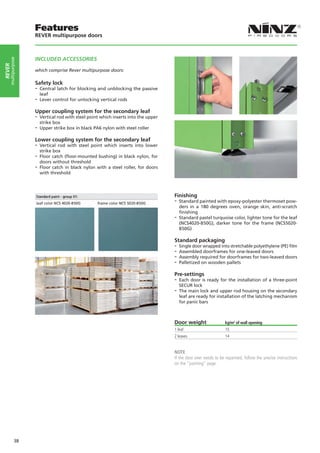
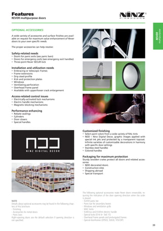
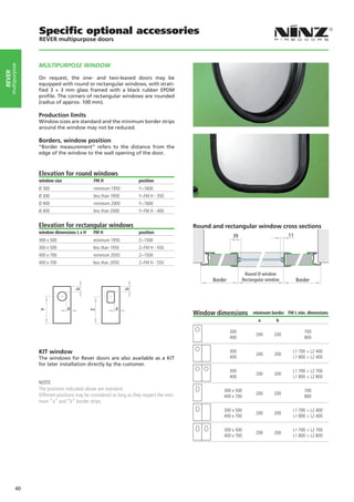
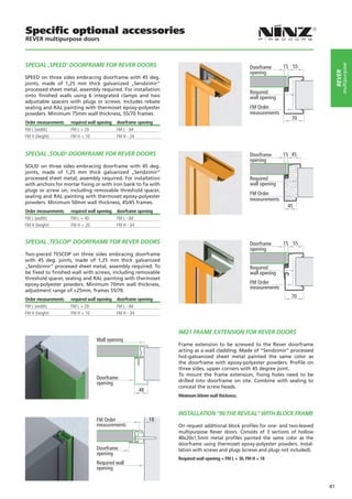
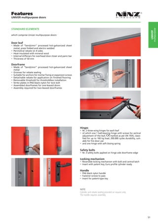
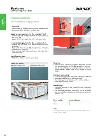
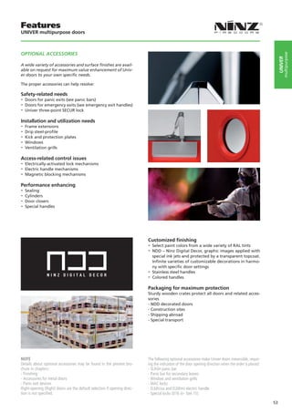
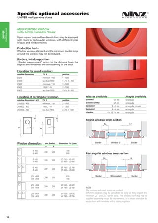
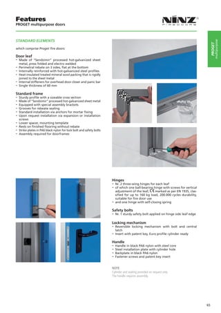
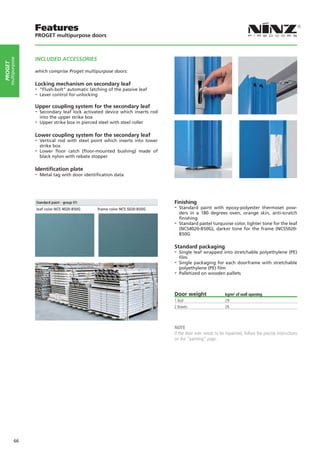
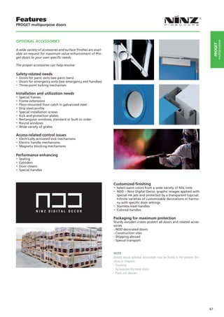
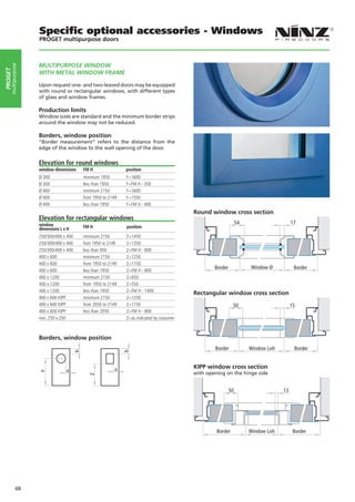
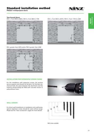
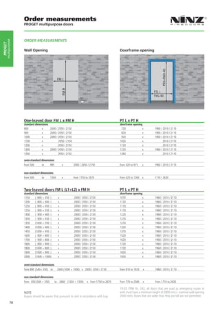
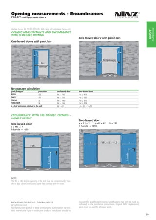
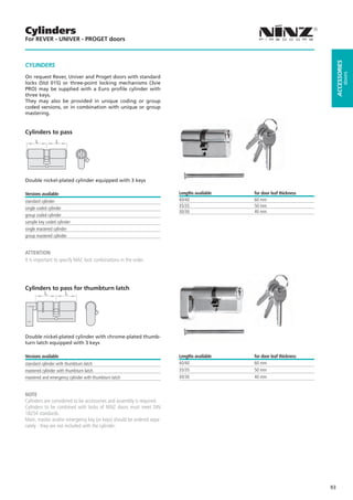
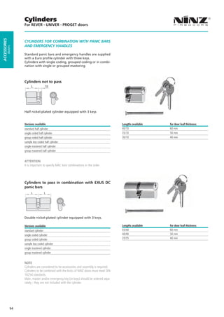
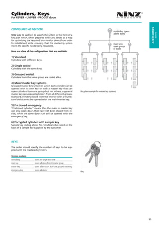
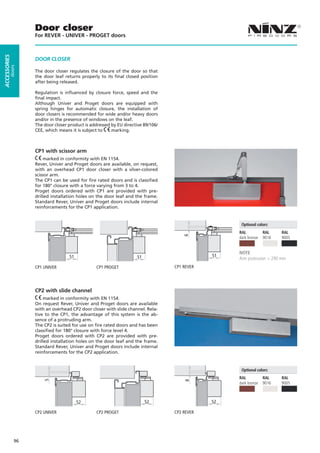
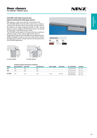
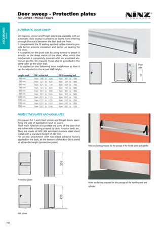
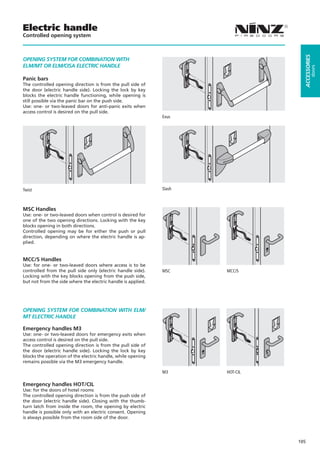
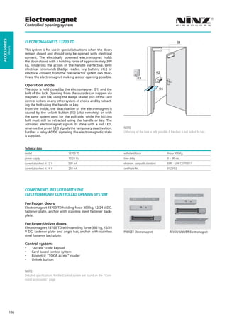
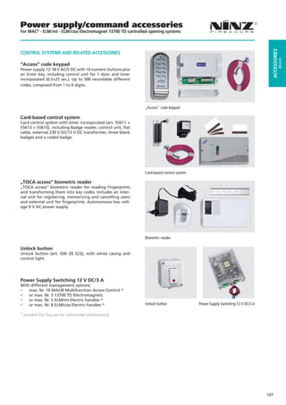
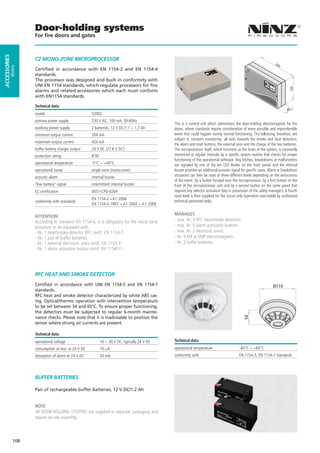
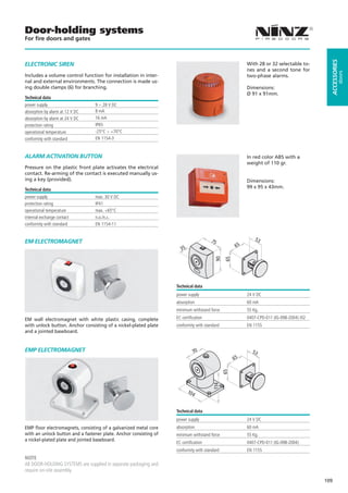
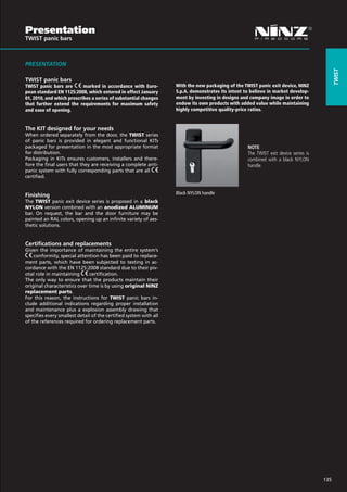
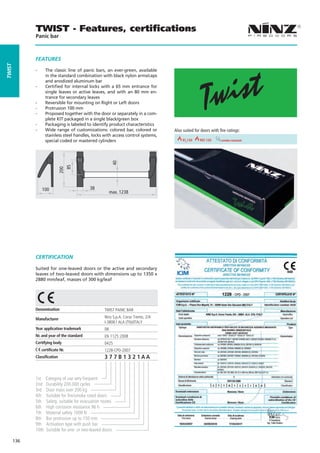
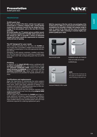
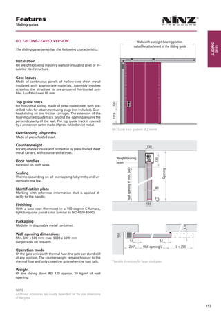
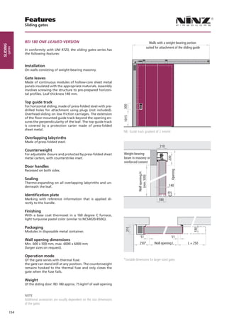
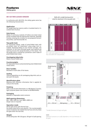
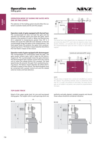
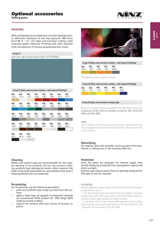
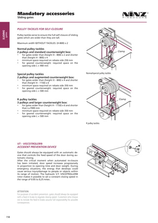
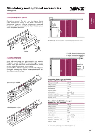
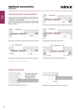
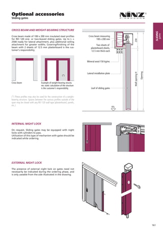
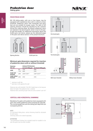
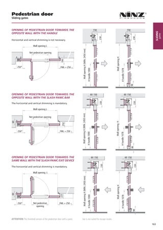
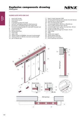
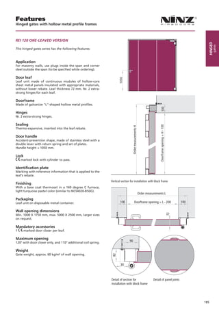
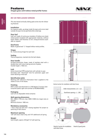
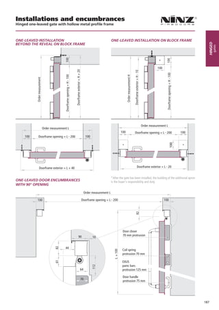
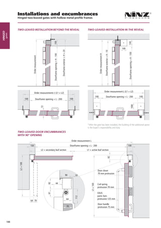
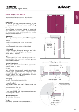
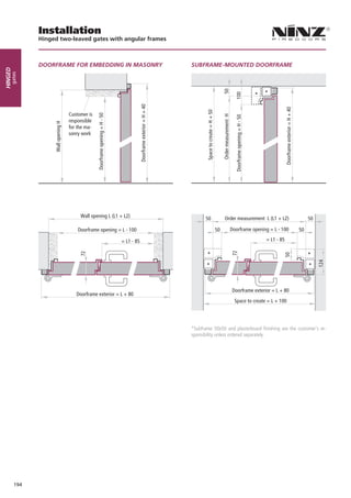
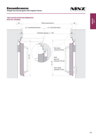
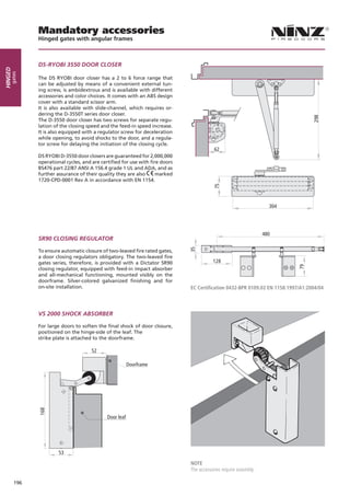
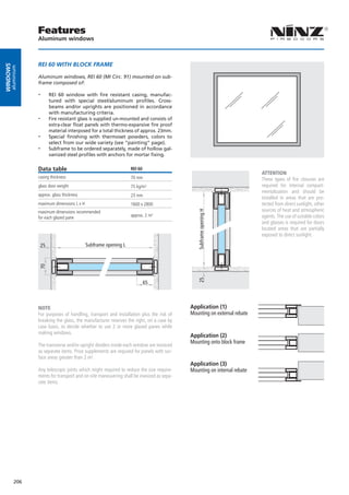
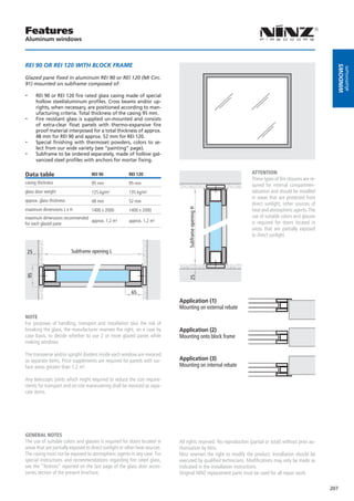
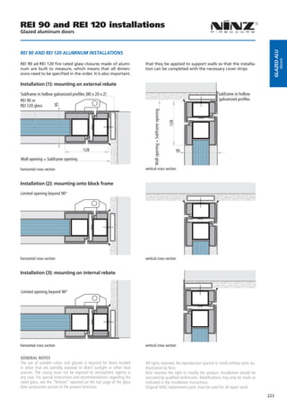
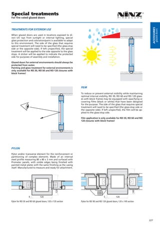
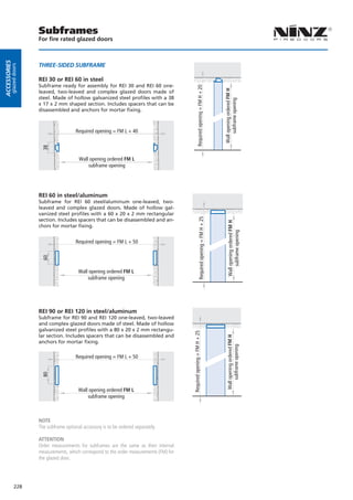
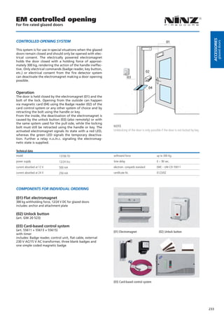
General brochure 2011


“more than firedoors“


                                   www.ninz.it
Main index NINZ

        COMPANY PRESENTATION                                           2-3

        FIRE DOORS Univer and Proget                                  4 - 33

        MULTIPURPOSE DOORS Rever, Univer and Proget                  34 - 79

        PAINTING AND NDD DECORATIONS                                 80 - 87

        DOOR ACCESSORIES devices and panic bars                     88 - 149

        GATES – sliding, telescopic, vertically sliding and hinged 150 - 199

        GLAZINGS, windows, glazed doors and accessories            200 - 243


Each of the above chapters is also accessible online www.ninz.it
                                                                               1
NINZ Fire doors
              Company presentation


              PRESENTATION - THE RELIABILITY OF EXPERIENCE
COMPANY


              Ninz S.p.A. is Italy’s leading producer of fire doors with a
              70% market share. Consolidated experience in the sector,
              familiarity with standards and optimal quality-price ratios
              are the company’s most distinguishing features. Over the
              years it has broadened its offer to include multipurpose
              metal doors and a wide range of accessories. In addition
              to Italy, Ninz S.p.A. also markets its products in numerous
              other European countries like France, Greece, Portugal,
              Romania, Spain, Slovenia... and countries outside of Eu-
              rope like Turkey, Russia and Panama.

              Production takes place in two different facilities - Bolzano
              and Ala (TN), where the offices for research and develop-
              ment, sales and logistics are also located. In Ala a third
              facility is currently under construction designed to further
              enhance production capacity.

              From its beginnings as a small family-owned metal works
              company in 1953, over the years the company has evolved to
              become a major industrial player with 250 employees. The
              main impetus for growth came from its owner, Karl Ninz,
              who first introduced the production of fire doors in 1976.


                                                                             PRODUCTION - VERSATILITY AND DESIGN

                                                                             The daily production capacity is 2000 doors, which are
                                                                             currently divided into the PROGET line (fire rated and
                                                                             multipurpose), the UNIVER line (fire rated and multipur-
                                                                             pose) and REVER line (multipurpose). Products are made
                                                                             to order for even the smallest quantities, satisfying the
                                                                             most demanding customers thanks to the wide variety of
                                                                             colors, accessories and windows available.

                                                                             Customization of the product reaches a pinnacle with the
                                                                             NDD technology (Ninz Digital Decor), a trademark, NINZ
                                                                             decorative painting which permits any theme (words, pic-
                                                                             tures, logos) to be reproduced on the door-leaf surface.
                                                                             As an expression of the NDD claim, fire doors are trans-
                                                                             formed into versatile design elements at the disposal of
                                                                             architects and designers.
                                                                             This project earned the company the prestigious “Design
                                                                             Security & Safety Award” in 2007


          2
NINZ Fire doors
Company presentation


DESIGN AND RESEARCH - EYES ON THE FUTURE


                                                                                                                                   COMPANY
Continuous product improvements are managed by a team
of expert engineers and technicians, who combine scrupu-
lous attention to fire regulations with the practical con-
cerns of builders, installers and locksmiths. This research,
for instance, has generated certified installation methods
for mounting fire doors on different types of support
structures, such as masonry, plasterboard and sub-frames.


Thanks to the in-depth study of foreign standards, Ninz
S.p.A. has also succeeded in certifying its products in a
number of foreign countries, including France, Slovenia,
Russia, Romania...

For long the company has been preparing itself for the
marking’s coming into force by designing and developing
innovative fire doors that meet the new European stand-
ards. The product represents a new conceptualization dif-
ferent from all that has been in terms of aesthetics as well
as functionality, promising excellent performance in every
possible setting.


                                                               MARKETING - A SERVICE-ORIENTED PERSPECTIVE

                                                               Thanks to their reliability and quality, Ninz fire doors are
                                                               used throughout Italy and in many countries across the
                                                               world in public buildings where safety is at a premium:
                                                               schools, hospitals, convention centers, shopping malls,
                                                               manufacturing sites, hotels, museums...

                                                               The distribution within Italy is capillary thanks to a dense
                                                               network of retailers supported by over one hundred sales
                                                               agents.
                                                               Punctual delivery - one of the company’s strongest points
                                                               - is guaranteed by the careful planning of the production
                                                               and by the quality transport services, which are both or-
                                                               ganized in-house.
                                                               The service that Ninz S.p.A. offers its customers is com-
                                                               pleted by the internal technical-sales office, which assists
                                                               agents and customers in the pre- and post-sales phases,
                                                               and by the fitting office, which directly follows product
                                                               installations at the customer’s request.

                                                               For international distribution, Ninz S.p.A. draws on (de-
                                                               pending on the country) agents, exclusive retailers and
                                                               networks of retailers supported by a dedicated internal
                                                               technical-sales office.

                                                               Daily shipment to France is possible thanks to the special
                                                               wooden-crates packaging and the local logistics network
                                                               that has been created. Due to its great success, this service
                                                               will soon be extended to other European countries.


                                                                                                                               3
“state of the art in fire
protection technology“
UNIVER NINZ Doors
                                     FIRE RATED VERSION


                                     FEATURES                                                                                6-9

                                     SPECIFIC OPTIONAL ACCESSORIES                                                         10 - 11

                                     DOOR CROSS SECTIONS - MEASUREMENTS                                                        12

                                     INSTALLATION METHODS                                                                      13

                                     ORDER MEASUREMENTS                                                                        14

                                     OPENING MEASUREMENTS - ENCUMBRANCE                                                        15


All measurements are in mm. We reserve the right to make unannounced technical changes to the contents of this brochure.
      Fire-rated closures are typically used for internal compartmentalization and have been designed for this purpose.
Features
                 UNIVER Fire doors


                 WHAT MAKES THEM SPECIAL?                                         One-leaved doors available in the following classes:
     fire door
UNIVER


                                                                                      EI230   EI230 260 - Sm -2C5 30 30 290 REI 60 60
                                                                                                  EI 260
                                                                                                   EI       EI 60 290
                                                                                                             REI REI EI
                                                                                                                EI               REI                     REI 90
                                                                                                                                                              RE
                 “Quality first”
                 -- Fully galvanized door, including the “hidden” parts
                 -- Made of “Sendzimir” processed hot-galvanized sheet metal
                 -- Corrosion protection also provided along cut edges of
                    the metal sheets
                 -- Painted  with epoxy-polyester thermoset powders in a
                    180 degrees (Celsius) oven
                 -- Substantial paint layer (70 microns plus)
                 -- Optimal corrosion resistance demonstrated by 500 hour
                    salt-fog test
                 -- Unaffected by severe climate changes, demonstrated by
                    2000 hours with +60° to -10° cycles at 75% humidity
                 -- Finishing with high-quality aesthetics
                 -- Orange skin anti-scratch structured paint
                 -- Customizable with wide selection of RAL colors
                 “Practicality of use”
                 -- Door reversibility*
                 -- Indication of door opening direction not necessary
                 -- Reduction of stock for retailers
                 -- Simplifies choices for end customers
                 -- Multiple installation methods for each door
                 -- Type approvals for anchors for mortar fixing or expan-
                   sion screws

                 “Conformity to standards”
                 -- In-house Ninz R&D with specialized testing equipment
                 -- Fire testing in accordance with UNI 9723 and EN 1634-1
                 -- Mechanical testing for the marking of accessories
                 -- -marked door accessories studied and sized to meet
                   standard European requirements                                 Two-leaved doors available in the following classes:
                 -- Careful selection of materials and manufacturing methods
                 -- Strict product testing for conformity to declared technical     EI230 260 - Sm -2C5 30 30 290 REI 60 60
                                                                                        EI        EI 60 REI EI
                                                                                                   REI                 REI                   REI 90 90
                                                                                                                                                  REI
                    standards
                 -- Absolute functional certainty over time
                 -- Doors “type approved” in compliance with M.D. 21
                    June 2004
                 -- Products delivered with the documentation required by
                    current regulations

                 “Manufacturing technology”
                 -- Manufacturing     in modern and functional facilities
                    which employ the latest technologies to maintain high
                    quality levels and product uniformity
                 -- The entire production process - from raw materials to
                    painted and packaged products - takes place inside
                    Ninz’s own facilities, ensuring a 360 degree door control


                     Left Left   RightRight       Left Left   RightRight


                                                                                  *except in combination with certain optional accessories

                                                                                  NOTE
                                                                                  The colors represented in the photos are not standard.

             6
Features
UNIVER Fire doors


STANDARD ELEMENTS FOR VERSIONS EI230 -


                                                                                                                                            fire door
                                                                                                                                       UNIVER
EI260, EI290 - REI 60 - REI 120

which comprise comprise Univer fire doors:

Door leaf
-- Made   of “Sendzimir” processed hot-galvanized sheet
   metal, press folded and electro welded
-- Perimetral rebate on 4 sides
-- Internally reinforced with hot-galvanized steel profiles
-- Heat-insulated with treated mineral wool
-- Internal stiffeners for overhead door closer and panic bar
-- 50 or 60 mm thickness, depending on fire rating
Doorframe
-- Made of “Sendzimir” processed hot-galvanized sheet metal
-- Grooves for thermo expansive sealing and rebate sealing
-- Suitable for anchors for mortar fixing or expansion screws
-- Detachable rebate for application on finished flooring
-- Removable threshold for thresholdless installation
-- Strike plates in PA6 black nylon for lock bolt and safety bolts
-- Assembled doorframes for one-leaved doors
-- Assembly required for two-leaved doorframes
Thermo expansive sealing
-- Mounted on vertical doorframe profiles and central ver-
  tical profiles on two-leaved doors
-- For on-site mounting on the doorframe’s upper cross-beam
-- Mounted above and below the EI290 and REI 120 leaves


                                                                     Hinges
                                                                     -- Nr. 2 three-wing hinges for each leaf
                                                                     -- of which one ball-bearing hinge with screws for vertical
                                                                        adjustment of the leaf,    marked as per EN 1935, clas-
                                                                        sified for up to 160 kg load, 200.000 cycles durability,
                                                                        suitable for fire door use
                                                                     -- and one hinge with self-closing spring

                                                                     Safety bolts
                                                                     -- Nr. 2 safety bolts on hinge side leaf edge
                                                                     Locking mechanism
                                                                     -- Reversible locking mechanism with bolt and central lock
                                                                     -- marked in conformity with EN 12209 standard
                                                                     -- Insert with patent key, Euro profile cylinder ready

                                                                     Handle
                                                                     -- Fire rated handle in black PA6 nylon with steel core
                                                                     -- Steel installation plate with cylinder hole
                                                                     -- Backplate in black PA6 nylon
                                                                     -- Fastener screws and patent key insert

                                                                     NOTE
                                                                     Cylinder and rebate sealing provided on request only.
                                                                     The handle requires assembly.


                                                                                                                                   7
Features
                 UNIVER Fire doors


                 INCLUDED ACCESSORIES
     fire door
UNIVER


                 which are part of the Univer fire doors:

                 Closing regulator
                 -- Two-leaved doors include an RC/STD closing regulator to
                      ensure the correct closing sequence of the leaves
                 --      marking in conformity with EN 1158 standard

                 Locking mechanism for secondary leaf
                 -- “Flush-bolt” automatic locking of the secondary leaf
                 -- Lever control for unlocking
                 Upper coupling system for the secondary leaf
                 -- Secondary  leaf lock activated device which inserts rod
                    into the upper strike box
                 -- Upper strike box in black PA6 nylon with steel roller
                 Lower coupling system for the secondary leaf
                 -- Vertical  rod with steel point which inserts into lower
                    strike box
                 -- Floor catch (floor-mounted floor catch) made of self-
                    extinguishing black nylon, for doors without threshold
                 -- Floor catch in self-extinguishing black nylon with a steel
                    roller, for doors with threshold

                 Identification plate
                 -- Metal tag with door identification data, in accordance
                      with current regulations


                                                                                 Finishing
                                                                                 -- Standard painted with epoxy-polyester thermoset pow-
                                                                                    ders in a 180 degrees oven, orange skin, anti-scratch
                                                                                    finishing
                                                                                 -- Standard pastel turquoise color, lighter tone for the leaf
                                                                                    (NCS4020-B50G), darker tone for the frame (NCS5020-B50G)

                                                                                 Standard packaging
                                                                                 -- Single door wrapped into stretchable polyethylene (PE) film
                                                                                 -- Assembled doorframes for one-leaved doors
                                                                                 -- Assembly required for doorframes for two-leaved doors
                                                                                 -- Palletized on wooden pallets


                                                                                 Door weight                                   kg/m2 of wall opening
                                                                                 class                      1 leaf             2 leaves
                                                                                 EI230                      34                 -
                                                                                 EI260                      36                 35
                                                                                 REI 60                     34                 33
                                                                                 EI290, REI 120             43                 41


                                                                                 NOTE
                                                                                 If the door ever needs to be repainted, follow the precise instructions
                                                                                 on the „painting“ page.
                                                                                 The closing regulator requires assembly.


             8
Features
UNIVER Fire doors


OPTIONAL ACCESSORIES


                                                                                                                                                                fire door
                                                                                                                                                           UNIVER
A wide variety of accessories and surface finishes are available
on request for maximum value enhancement of Univer doors to
your own specific needs.

The proper accessories can help resolve:

Safety-related needs
-- Doors for panic exits (see panic bars)
-- Doors for emergency exits (see emergency exit handles)
-- Open doors which must be closed in case of fire (see leaf
  holding systems)

Installation and utilization needs
-- Frame extensions
-- Drip steel-profile
-- Special fastener screws
-- Kick and protection plates
-- Windows
Access-related control issues
-- Electrically-activated lock mechanisms
-- Electric handle mechanisms
-- Magnetic blocking mechanisms
Performance enhancing
-- Sealing
-- Cylinders
-- Door closers
-- Special closing regulators
-- Special handles


                                                                          Customized finishing
                                                                          -- Select paint colors from a wide variety of RAL tints
                                                                          -- NDD – Ninz Digital Decor, graphic images applied      with
                                                                             special ink jets and protected by a transparent topcoat.
                                                                             Infinite varieties of customizable decorations in harmony
                                                                             with specific door settings
                                                                          -- Stainless steel handles
                                                                          -- Colored handles
                                                                          Packaging for maximum protection
                                                                          Sturdy wooden crates protect all doors and related ac-
                                                                          cessories
                                                                          -- NDD decorated doors
                                                                          -- Construction sites
                                                                          -- Shipping abroad
                                                                          -- Special transport


NOTE                                                                      The following optional accessories make Univer doors irreversible, requir-
Details on the optional accessories may be found in the following chap-   ing the indication of the door opening direction when the order is placed:
ters of this brochure:                                                    - SLASH panic bar
- Finishing                                                               - Panic bar for secondary leaves
- Accessories for metal doors                                             - Windows
- Panic bars                                                              - MAC lock
Right-opening doors are the default selection if opening direction is     - ELM/cisa and ELM/mt electric handle
not specified.                                                            - Special locks (016 tir- Stel 15)

                                                                                                                                                       9
Specific optional accessories
                 UNIVER Fire doors


                 WINDOW WITH FIRE RATED GLASS
     fire door
UNIVER


                 Upon request all one- and two-leaved fire doors, exclud-
                 ing those EI230 rated, may be equipped with round or
                 rectangular windows with fire rated stratified glass and
                 window frames. Windows not possible for one-leaved REI
                 doors with FM L (wall opening) above 1167mm.

                 Limits prescribed by standard
                 According to standards UNI 9723 and EN 1634-1, windows
                 may be smaller but not larger than the test sample size,
                 and the reverse holds true for the border strip around the
                 window which may be wider but not thinner.
                 The following limits correspond with these restrictions.

                 Borders, window position
                 “Border measurement” refers to the distance from the
                 edge of the window to the wall opening of the door.


                 Elevation for round windows
                 window size                  FM H                      position
                 Ø 300                        minimum 2050              Y=1600
                 Ø 300                        less than 2050            Y=FM H - 450
                                                                                            Round window cross section
                 Ø 400                        minimum 2150              Y=1600
                 Ø 400                        from 2050 to 2149         Y=1550                                    54                           17
                 Ø 400                        less than 2050            Y=FM H - 500

                 Elevation for rectangular windows
                 window dimensions L x H FM H                           position
                 250/300 x 400                minimum 2150              Z=1450
                 250/300 x 400                from 2050 to 2149         Z=1350                         Border              Window Ø               Border
                 250/300 x 400                less than 2050            Z=FM H -700

                                                                                            Rectangular window cross section
                                     b


                                                                  b


                                                                                                                50                              15

                                 a                            a
                 Y


                                              Z


                                                                                                       Border             Window LxH              Border
                 Window                  min. border     min. border       dimensions
                 dimensions                  EI2             REI            FM L min.
                                          a          b    a       b

                               Ø 300                                           740
                                                                                            Window thickness
                                         220      300    220      300                       EI260, REI 60 21 mm            EI290 37 mm               REI 120 53 mm
                               Ø 400                                           840

                               Ø 300                                     L1 740 + L2 min.
                                         220      300    220      300                       NOTE
                               Ø 400                                     L1 840 + L2 min.
                                                                                            The positions indicated above are standard.
                                                                                            Different positions may be considered as long as they respect the mini-
                               Ø 300                                     L1 740 + L2 740
                                         220      300    220      300                       mum “a” and “b” border strips. The window itself may not be supplied
                               Ø 400                                     L1 840 + L2 840
                                                                                            separately except for replacements. It is always advisable for doors with
                                                                                            windows to be equipped with door closers for controlled closing.
                           250 x 400                                    EI2=750 REI=850
                                         250      300    300      300
                           300 x 400                                    EI2=800 REI=900     ATTENTION
                                                                                            REI windows become opaque on exposure to temperatures of 40 de-
                           250 x 400
                                         300      300    300      300
                                                                         L1 850 + L2 min.   grees or higher, or when installed outside and exposed to UV radia-
                           300 x 400                                     L1 900 + L2 min.   tion. Minor aesthetic imperfections or tiny air bubbles do not compro-
                                                                                            mise the fire resistance of the glass, and do not constitute grounds for
                           250 x 400                                     L1 850 + L2 850    claims. For special instructions and recommendations for fire windows,
                                         300      300    300      300
                           300 x 400                                     L1 900 + L2 900    see the “Notices” reported on the last page of the window accessories
                                                                                            section of the present brochure.
           10
Specific optional accessories
UNIVER Fire doors


FRAME EXTENSIONS FOR UNIVER DOORS


                                                                                                                                              fire door
                                                                                                                                         UNIVER
IM 11 - IM 12
Frame extensions to be mounted in addition to the Univer                                               Doorframe
frame acting as a wall cladding. Made of “Sendzimir” proc-                                             opening
essed hot-galvanized sheet metal and painted the same
color as the doorframe with epoxy-polyester powders. Pro-                                              Wall opening
file on three sides, upper corners with 45 degree joint, fixing
with screws and plugs (screws and plugs not included).
                                                                                                                               73
IM 11: for 50mm door thickness, for installation on 70mm (min.) wall
thickness
IM 12: for 60mm door thickness, for installation on 80mm (min.) wall
thickness

IM 13 - IM 14
Telescopic frame extension to be screwed to the Univer
doorframe acting as a wall cladding. Consists of two overlap-
ping profiles with a 25mm adjustable range. Made of “Send-                                             Doorframe
zimir” processed hot-galvanized sheet metal painted the                                                opening
same color as the doorframe with epoxy-polyester powders.
Profile on three sides, upper corners with 90 degree joint.
                                                                                                       Wall opening
Complete with fastener screws. To mount the frame exten-
sion, fixing holes need to be drilled into doorframe on site.
Combine with sealing to conceal the screw heads.                                                                               50
IM 13: for 50mm door thickness, for installation on 125mm (min.) wall
thickness
IM 14: for 60mm door thickness, for installation on 135mm (min.) wall
thickness


REBATE SEALING

FF/CR sealing (for EI2 doors) and FF sealing (for REI doors)
in black extruded profile to be pressed into the dedicated
groove in the perimetral frame.

FF sealing in black extruded profile self-adhesive for ap-
plication to the central joint of two-leaved doors.


NOTE
Upon request sealing supplied for single doors to be cut and mounted
on site.


ENHANCED PERFORMANCE (Sm, C5)

Mandatory accessories
Enhanced performance         features                     type          mandatory optional acc.        reference in brochure
                                                                        - rubber seal FF/CR            UNIVER fire door
                                                          1 leaf
                                                                        - Nr. 1 automatic door sweep   ACCESSORIES
EI260-Sm                     Smoke control Door
                                                                        - rubber seal FF/CR            UNIVER fire door
                                                          2 leaves
                                                                        - Nr. 2 automatic door sweep   ACCESSORIES
                                                          1 leaf        - Nr. 1 door closer            ACCESSORIES
EI260-C5                     Durability: 200,000 cycles
                                                          2 leaves      - Nr. 2 door closers           ACCESSORIES


                                                                                                                                    11
Door cross sections - Measurements
                 UNIVER Fire doors


                 One-leaved doors                                                                                                               Doors without lower threshold
     fire door
UNIVER


                 Horizontal cross section                                                                                                       Vertical cross section


                                                 Doorframe opening = FM L -74


                                                                                                                                                                                                                              Exterior doorframe = FM H +13
                                                                                                                                                               Doorframe opening = FM H -40


                                                                                                                                                                                                   +15
                                                                                                                                                                                                     Wall opening FM H +5
                                                                                          +20
                                                      Wall opening FM L +10

                                                 Exterior doorframe = FM L +32
                                                                                                                                                                                                                                                              FFL


                 Doors with internal and external lower thresholds	                                                                             Doors with internal lower threshold
                 Vertical cross section                                                                                                         Vertical cross section
                                                                                           Exterior doorframe = FM H +34


                                                                                                                                                                                                                            Exterior doorframe = FM H +13
                                                                  +15
                             Doorframe opening


                                                                   Wall opening FM H +5


                                                                                                                                                                                                   +15
                                                                                                                                                                                                    Wall opening FM H +5
                                = FM H -72


                                                                                                                                                               Doorframe opening
                                                                                                                                                                  = FM H -72


                     FFL


                                                                                                                                                                                                                                                              FFL
                                                                                                                                                              32


                 Two-leaved doors
                 Horizontal section

                                                                                                                           Doorframe opening = FM L - 80

                                                                                                                                                            Active leaf opening = L1 -75


                                                                         L2                                                                                                                   L1
                                                                                                                                             +20
                                                                                                                           Wall opening FM L +10 = L1+ L2

                                                                                                                           Exterior doorframe = FM L +26


                                                                                                                                                NOTE                     +20        +15
                 Leaf thickness                                                                                                                 The tolerances FM L +10 , FM H +5 of the indicated measurements
                 class                               thickness                                                                                  make it easier to fill the gap between the wall and the doorframe with
                 EI230, REI 60                       50 mm                                                                                      cement mortar.
                 EI260, EI290, REI 120               60 mm
                                                                                                                                                FFL = Finished floor level


           12
Installation methods
UNIVER Fire doors


INSTALLATION WITH ANCHORS FOR MORTAR FIXING                      ANCHOR POSITIONING


                                                                                                                                               fire door
                                                                                                                                          UNIVER
                                                                 One-leaved doors
                                                                 Right opening	                    Left opening


For mortar fixing, appropriate cuts will need to be created in
the walls (section 80 x 200 mm). The anchors should be bent
and blocked inside the wall. For fire sealing purposes and
mechanical hold, the space between the doorframe and the
masonry should always be filled with concrete mortar.
                                                                                                    

                                                                 Two-leaved doors
                                                                 Right opening


INSTALLATION FOR EXPANSION SCREWS FIXING

For the installation with expansion screws, the anchors
serve as spacers and should not be bent. Using Würth
type art. 0910436112 plugs or similar (supplied at the
customer‘s expense), installation requires holes to be
                                                                 Left opening
drilled through the thermo expansive sealing. The door-
frame has pre-drilled holes. For fire sealing purposes and
mechanical hold, the space between the doorframe and
the masonry should always be filled with concrete mortar.


                                                                 NOTE
                                                                 Proper installation requires 80 x 200 mm holes to be dug into the
                                                                 masonry.


                                                                                                                                     13
Order measurements
                 UNIVER Fire doors


                 ORDER MEASUREMENTS
     fire door
UNIVER


                 Wall opening	                           Doorframe opening
                                                                                                    One-leaved doors                           Two-leaved doors
                                                                                                    PT L = FM L - 74                           PT L = FM L - 80
                                                                                                    PT H = FM H - 40                           PT H = FM H - 40


                                                                                                    NOTE
                                                                                                    Buyers should be aware that pursuant to and in accordance with Leg-
                                                                                                    islative Decree dd. 19.09.1994 Nr. 626, resp. of Legislative Decree dd.
                                                                                                    19.03.1996 Nr. 242, all doors used for emergency exits must have a
                                                                                                    minimum height of 2000 mm (= nominal wall opening 2040 mm). Unless
                                                                                                    specified otherwise by the customer, two-leaved standard, semi-standard
                                                                                                    and customized doors are supplied with a right-pull opening direction.
                                                        

                 One-leaved EI230, EI260, EI290 doors                                               One-leaved REI 60, REI 120 doors
                 FM L x FM H               PT L x PT H                                              FM L x FM H              PT L x PT H
                 standard dimensions                     doorframe opening                          standard dimensions                        doorframe opening
                 800           x   2050 / 2150           726               x       2010 / 2110      800             x   2050 / 2150            726               x       2010 / 2110
                 900           x   2050 / 2150           826               x       2010 / 2110      900             x   2050 / 2150            826               x       2010 / 2110
                 1000          x   2050 / 2150           926               x       2010 / 2110      1000            x   2050 / 2150            926               x       2010 / 2110
                 1100          x   2050 / 2150           1026              x       2010 / 2110      1100            x   2050 / 2150            1026              x       2010 / 2110
                                                                                                    1200            x   2050 / 2150            1126              x       2010 / 2110
                 semi-standard dimensions                                                           1350            x   2050 / 2150            1276              x       2010 / 2110
                 from 540                                from 466
                                x 2050 / 2150                              x 2010 / 2110
                 to 1150                                 to 1076                                    semi-standard dimensions
                                                                                                    from 540                                   from 466
                 non-standard dimensions                                                                            x 2050 / 2150                                x       2010 / 2110
                                                                                                    to 1345                                    to 1271
                 from 540          from 1780             from 466                  from 1740
                                x                                          x                        non-standard dimensions
                 to 1150           to 2150               to 1076                   to 2110
                                                                                                    from 540          from 1780                from 466                  from 1740
                                                                                                                   x                                             x
                                                                                                    to 1330           to 2150                  to 1256                   to 2110
                                                                                                    from 1331         from 1938                from 1257                 from 1898
                                                                                                                   x                                             x
                                                                                                    to 1350           to 2150                  to 1276                   to 2110


                 Two-leaved EI260, EI290 doors                                                      Two-leaved REI 60, REI 120 doors
                 FM L (L1+L2) x FM H           PT L x PT H                                          FM L (L1+L2) x FM H          PT L x PT H
                 standard dimensions                            doorframe opening                   standard dimensions                               doorframe opening
                 1200   ( 600 + 600)   x   2050 / 2150          1120           x      2010 / 2110   1150   ( 750   + 400 )   x   2050 / 2150          1070           x      2010 / 2110
                 1200   ( 700 + 500)   x   2050 / 2150          1120           x      2010 / 2110   1200   ( 800   + 400 )   x   2050 / 2150          1120           x      2010 / 2110
                 1300   ( 650 + 650)   x   2050 / 2150          1220           x      2010 / 2110   1250   ( 800   + 450 )   x   2050 / 2150          1170           x      2010 / 2110
                 1300   ( 800 + 500)   x   2050 / 2150          1220           x      2010 / 2110   1300   ( 900   + 400 )   x   2050 / 2150          1220           x      2010 / 2110
                 1400   ( 700 + 700)   x   2050 / 2150          1320           x      2010 / 2110   1350   ( 900   + 450 )   x   2050 / 2150          1270           x      2010 / 2110
                 1400   ( 900 + 500)   x   2050 / 2150          1320           x      2010 / 2110   1400   (1000   + 400 )   x   2050 / 2150          1320           x      2010 / 2110
                 1500   ( 750 + 750)   x   2050 / 2150          1420           x      2010 / 2110   1450   (1000   + 450 )   x   2050 / 2150          1370           x      2010 / 2110
                 1600   ( 800 + 800)   x   2050 / 2150          1520           x      2010 / 2110   1600   ( 800   + 800 )   x   2050 / 2150          1520           x      2010 / 2110
                 1700   ( 900 + 800)   x   2050 / 2150          1620           x      2010 / 2110   1700   ( 900   + 800 )   x   2050 / 2150          1620           x      2010 / 2110
                 1800   ( 900 + 900)   x   2050 / 2150          1720           x      2010 / 2110   1800   ( 900   + 900 )   x   2050 / 2150          1720           x      2010 / 2110
                 1900   (1000 + 900)   x   2050 / 2150          1820           x      2010 / 2110   1900   (1000   + 900)    x   2050 / 2150          1820           x      2010 / 2110
                 2000   (1000 +1000)   x   2050 / 2150          1920           x      2010 / 2110   2000   (1000   +1000)    x   2050 / 2150          1920           x      2010 / 2110

                 semi-standard dimensions                                                           semi-standard dimensions
                 from 1000 (500+500)                            from 920                            from 940 (540+400)                                from 860
                                     x 2050 / 2150                             x      2010 / 2110                         x 2050 / 2150                              x      2010 / 2110
                 to 2000 (1000+1000)                            to 1920                             to 2000 (1000+1000)                               to 1920

                 non-standard dimensions                                                            non-standard dimensions
                 from 1000 (500+500)   from 1780                from 920              from 1740     from 940 (540+400)      from 1780                 from 860              from 1740
                                     x                                         x                                         x                                           x
                 to 2000 (1000+1000)   to 2150                  to 1920               to 2110       to 2000 (1000+1000)     to 2150                   to 1920               to 2110

           14
Opening measurements - Encumbrances
UNIVER Fire doors


OPENING MEASUREMENT AND ENCUMBRANCE


                                                                                                                                                                fire door
                                                                                                                                                           UNIVER
WITH 90 DEGREE OPENING

One-leaved doors with panic bar                                           Two-leaved doors with panic bars


Net passage calculation                          EI230 - REI 60           REI 60                  EI260 - EI290 - REI 120   EI260 - EI290 - REI 120
panic bar type            protrusion             one-leaved doors         two-leaved doors        one-leaved doors          two-leaved doors
EXUS                      125                    FML - 226                FML - 384               FML - 236                 FML - 404
TWIST                     100                    FML - 201                FML - 334               FML - 211                 FML - 354
SLASH                     75                     FML - 176                FML - 284               FML - 186                 FML - 304
TOUCHBAR                  74                     FML - 175                FML - 282               FML - 185                 FML - 302
z = leaf protrusion                                                       L1 + 35                                           L1 + 35
                                                 FML + 29                                         FML + 29
relative to the wall                                                      L2 + 64                                           L2 + 64


ENCUMBRANCE WITH 180 DEGREE OPENING -
HANDLE HEIGHT
                                                                          Two-leaved doors
One-leaved doors                                                          x = L1 + 5     y = L2 + 35
x = FML + 5                                                               h handle = FMH/2 + 50
h handle = FMH/2 + 50                                                     b = 130 (only in the presence of panic bars or M14 handles)


NOTE
The 90 or 180 degree opening of the leaf could be compromised if
handle or door closer protrusions come into contact with the wall.


UNIVER - GENERAL NOTES
All rights reserved.                                                      Installation should be executed by qualified technicians.
No reproduction (partial or total) without prior authorization by Ninz.   Modifications may only be made as indicated in the installation instruc-
Ninz reserves the right to modify the product.                            tions. Original NINZ replacement parts must be used for all repair work.

                                                                                                                                                      15
“fire protection excellence,
flexibility custom-made“
PROGET NINZ Doors
                                     FIRE RATED VERSION

                                     FEATURES                                                                              18 - 21

                                     SPECIFIC OPTIONAL ACCESSORIES                                                         22 - 25

                                     DOOR CROSS SECTIONS - MEASUREMENTS                                                        26

                                     INSTALLATION METHODS                                                                      27

                                     OPTIONAL INSTALLATION METHODS                                                             28

                                     DRY WALL INSTALLATION                                                                 29 - 30

                                     ORDER MEASUREMENTS - HANDLE HEIGHTS                                                   31 - 32

                                     OPENING MEASUREMENTS - ENCUMBRANCE                                                        33


All measurements are in mm. We reserve the right to make unannounced technical changes to the contents of this brochure.
      Fire-rated closures are typically used for internal compartmentalization and have been designed for this purpose.
Features
                  PROGET Fire doors


                  THE FIRE DOOR IN A CLASS OF ITS OWN                                  One-leaved doors available in the following classes:
     fire doors
PROGET


                                                                           REI 30 30
                                                                                REI    REI 60 60
                                                                                            REI                             REI 90 90
                                                                                                                                 REI
                  “Indisputable quality”
                  -- Especially sturdy door for safe functioning over time
                  -- Ideal for application to uneven or weak walls
                  -- Fully isolated frame for true “dry wall installation”
                  -- Built to order for all kinds of requests
                  -- Fully galvanized door, including the “hidden” parts
                  -- Made of hot-galvanized sheet metal, “Sendzimir” proc-
                    essed
                  -- Corrosion protection also provided along cut edges of
                     the metal sheets
                  -- Painted  with epoxy-polyester thermoset powders in a
                     180 degrees (Celsius) oven
                  -- Substantial paint layer (70 microns plus)
                  -- Optimal corrosion resistance demonstrated by 500 hour
                     salt-fog test
                  -- Unaffected by severe climate changes, demonstrated by
                     2000 hours with +60° to -10° cycles at 75% humidity
                  -- Finishing with high-quality aesthetics
                  -- Orange skin anti-scratch structured paint
                  -- Customizable with wide selection of RAL colors
                  -- “Practicality of use”
                  -- Truly sturdy frame that facilitates anchoring to the wall
                  -- Suitable for all wall types
                  -- Different installation methods to choose from
                  -- Significantly reduced installation times
                  -- Type approvals for multiple installations to different
                    wall types
                  -- Ample size range
                  -- Wide variety of accessories
                                                                                       Two-leaved doors available in the following classes:
                  “Conformity to standards”
                  -- In-house Ninz R&D with specialized testing equipment REI 30
                                                                       REI 30          REI 60 60
                                                                                            REI                             REI 90 90
                                                                                                                                 REI
                  -- Fire testing in accordance with UNI 9723 and EN 1634-1
                  -- Mechanical testing for the marking of accessories
                  -- marked door accessories studied and sized to meet
                    standard European requirements
                  -- Careful selection of materials and manufacturing methods
                  -- Strict product testing for conformity to declared techni-
                    cal standards
                  -- Absolute functional certainty over time
                  -- Doors “type approved” in compliance    with M.D. 21
                     June 2004
                  -- Products delivered with the documentation required by
                     current regulations

                  “Manufacturing technology”
                  -- Manufacturing     in modern and functional facilities
                     which employ the latest technologies to maintain high
                     quality levels and product uniformity
                  -- The entire production process - from raw materials to
                     painted and packaged products - takes place inside
                     Ninz’s own facilities, ensuring a 360 degree door control

                  Opening direction
                  Opening direction needs to be indicated while ordering


                       Left Left       Right
                                   Right           Left Left       Right
                                                               Right


                                                                                       NOTE
                                                                                       The colors represented in the photos are not standard.
                                                                                       Door closer provided upon request only.

            18
Features
PROGET Fire doors


STANDARD ELEMENTS


                                                                                                                                                 fire doors
                                                                                                                                            PROGET
which comprise Proget fire doors:


Door leaf
-- Made    of “Sendzimir” processed hot-galvanized sheet
   metal, press folded and electro welded
-- Perimetral rebate on 3 sides, flat at the bottom
-- Internally reinforced with hot-galvanized steel profiles
-- Heat-insulated treated mineral wool packing that is rig-
   idly joined to the sheet metal
-- Internal stiffeners for overhead door closer and panic bar
-- Single thickness of 60 mm

Standard frame
-- Sturdy profile with a sizeable cross section
-- Made of “Sendzimir” processed hot-galvanized             sheet
   metal
-- Equipped with special assembly brackets
-- Grooves for thermo expansive sealing and rebate sealing
-- Standard installation via anchors for mortar fixing
-- Upon request installation via expansion screws or screws
   onto the subframe
-- Lower spacer, mounting template
-- Rests on finished flooring without rebate
-- Strike plates in PA6 black nylon for lock bolt and safety bolts
-- Assembly required for doorframes
Thermo expansive sealing
-- Mounted on vertical doorframe profiles and central ver-
  tical profiles (for two-leaved doors)
-- Mounted above and below the leaves depending on the
  certification


                                                                     Hinges
                                                                     -- Nr. 2 three-wing hinges for each leaf
                                                                     -- of which one ball-bearing hinge with screws for vertical
                                                                        adjustment of the leaf,     marked as per EN 1935, classi-
                                                                        fied for up to 160 kg load, 200.000 cycles durability, suit-
                                                                        able for fire door use
                                                                     -- and one hinge with self-closing spring
                                                                     Safety bolts
                                                                     - Nr. 1 or 2 safety bolts applied on hinge side leaf edge

                                                                     Locking mechanism
                                                                     -- Reversible locking mechanism with bolt and central latch
                                                                     -- marked in conformity with EN 12209 standard
                                                                     -- Insert with patent key, Euro profile cylinder ready

                                                                     Handle
                                                                     - Fire rated handle in black PA6 nylon with steel core
                                                                     - Steel installation plate with cylinder hole
                                                                     - Backplate in black PA6 nylon
                                                                     - Fastener screws and patent key insert


NOTE
Cylinder and rebate sealing provided on request only.
The handle requires assembly.


                                                                                                                                       19
Features
                  PROGET Fire doors


                  INCLUDED ACCESSORIES
     fire doors
PROGET


                  which comprise Proget fire doors:

                  Closing regulator
                  -- Standard two-leaved doors include an RC/STD Closing
                    regulator to ensure the correct closing sequence of the
                    leaves
                  -- marking in conformity with EN 1158 standard
                  Locking mechanism for secondary leaf
                  -- “Flush-bolt” automatic locking of the secondary leaf
                  -- Lever control for unlocking
                  Upper coupling system for the secondary leaf
                  -- Secondary leaf lock activated device which inserts rod
                    into the upper strike box
                  -- Upper strike box in pierced steel with steel roller
                  Lower coupling system for the secondary leaf
                  -- Vertical rod with steel point which inserts into lower
                     strike box
                  -- Lower floor catch (floor-mounted bushing) made of
                     self-extinguishing black nylon with rebate stopper

                  Identification plate
                  -- Metal tag with door identification data, in accordance
                    with current regulations


                                                                                            Finishing
                                                                                            -- Standard painted with epoxy-polyester thermoset pow-
                                                                                               ders in a 180 degrees oven, orange skin, anti-scratch
                                                                                               finishing
                                                                                            -- Standard pastel turquoise color, lighter tone for the leaf
                                                                                               (NCS4020-B50G), darker tone for the frame (NCS5020-
                                                                                               B50G)

                                                                                            Standard packaging
                                                                                            -- Single leaf wrapped into stretchable polyethylene (PE)
                                                                                              film
                                                                                            -- Single packaging for each doorframe with stretchable
                                                                                              polyethylene (PE) film
                                                                                            -- Palletized on wooden pallets


                                                                                            Door weight                class         kg/m2 of wall opening
                                                                                            1 leaf                     REI 60        37
                                                                                            2 leaves                   REI 60        35
                                                                                            1 leaf                     REI 120       42
                                                                                            2 leaves                   REI 120       40


                  NOTE
                  If the door ever needs to be repainted, follow the precise instructions
                  on the “painting” page.


            20
Features
PROGET Fire doors


INSTALLATION ONTO OTHER WALL TYPES


                                                                                                                                                        fire doors
                                                                                                                                                   PROGET
Other types of installation are possible, all of which have been
rigorously certified and approved
-- Frame for dry wall installation with expansion screws
-- Frame for dry wall installation with screws onto the subframe
-- Frame for installation on plasterboard
-- Embracing frame for plasterboard installation

OPTIONAL ACCESSORIES

A wide variety of accessories and surface finishes are available
on request for maximum value enhancement of Proget doors to
your own specific needs. The proper accessories can help resolve:

Safety-related needs
-- Doors for panic exits (see panic bars)
-- Doors for emergency exits (see emergency exit handles)
-- Open doors which must be closed in case of fire (see leaf
  holding systems)

Installation and utilization needs
-- Frame extensions
-- Floor mounted floor catch in galvanized steel
-- Drip steel-profile
-- Special fastener screws
-- Kick and protection plates
-- Rectangular windows, standard dimensions or built to order
-- Round windows
Access-related control issues
-- Electrically-activated lock mechanisms
-- Electric handle mechanisms
-- Magnetic blocking mechanisms


                                                                    Performance enhancing
                                                                    -- Sealing
                                                                    -- Cylinders
                                                                    -- Door closers
                                                                    -- Special closing regulators
                                                                    -- Special handles

                                                                    Customized finishing
                                                                    -- Select paint colors from a wide variety of RAL tints
                                                                    -- NDD – Ninz Digital Decor, graphic images applied with
                                                                       special ink jets and protected by a transparent topcoat.
                                                                       Infinite varieties of customizable decorations in harmo-
                                                                       ny with specific door settings
                                                                    -- Stainless steel handles
                                                                    -- Colored handles
                                                                    Packaging for maximum protection
                                                                    Sturdy wooden crates protect all doors and related acces-
                                                                    sories
                                                                    -- NDD decorated doors
                                                                    -- Construction sites
                                                                    -- Shipping abroad
                                                                    -- Special transport

                                                                    NOTE
                                                                    Details on the optional accessories may be found in the following chap-
                                                                    ters of this brochure:
                                                                    - Finishing
                                                                    - Accessories for metal doors
                                                                    - Panic bars


                                                                                                                                              21
Specific optional accessories
                  PROGET Fire doors


                  WINDOW WITH FIRE RATED GLASS
     fire doors
PROGET


                  Upon request all one- and two-leaved fire doors REI 60
                  and REI 120 may be equipped with round or rectangu-
                  lar windows with fire rated stratified glass and window
                  frames.

                  Limits prescribed by regulations
                  According to standards UNI 9723 and EN 1634-1, windows
                  may be smaller but not larger than the test sample size,
                  and the reverse holds true for the border strip around the
                  window which may be wider but not thinner.
                  The following limits correspond with these restrictions.

                  Borders, window position
                  “Border measurement“ refers to the distance from the
                  edge of the window to the wall opening of the door.


                  Elevation for round windows
                  window size                   FM H                 position
                  Ø 300                         minimum 2050         Y=1600               Round window cross section
                  Ø 300                         less than 2050       Y=FM H - 450                              54                            17
                  Ø 400                         minimum 2150         Y=1600
                  Ø 400                         from 2050 to 2149    Y=1550
                  Ø 400                         less than 2050       Y=FM H - 500

                  Elevation for rectangular windows
                  window dimensions L x H       FM H                 position
                  300 x 400                     minimum 2150         Z=1450                          Border             Window Ø               Border
                  300 x 400                     from 2050 to 2149    Z=1350
                  300 x 400                     less than 2050       Z=FM H -700
                  400 x 600                     minimum 2150         Z=1250
                  400 x 600                     from 2050 to 2149    Z=1150               Rectangular window cross section
                  400 x 600                     less than 2050       Z=FM H - 900                             50                            15
                  400 x 1200                    minimum 2150         Z=650
                  400 x 1200                    from 2050 to 2149    Z=550
                  400 x 1200                    less than 2050       Z=FM H - 1500


                                                                                                     Border            Window LxH              Border
                                    b


                                                                 b


                                a                         a
                  Y


                                                                                          Window thickness
                                            Z


                                                                                          class            glass thickness
                                                                                          REI 60           21 mm
                                                                                          REI 120          53 mm


                  NOTE                                                                    ATTENTION
                  Position and measurements indicated above are for standard.             REI windows become opaque on exposure to temperatures of 40 de-
                  Different positions and measurements may be considered as long as       grees or higher, or when installed outside and exposed to UV radia-
                  they respect the minimum “a” and “b” border strips and maximal          tion. Minor aesthetic imperfections or tiny air bubbles do not compro-
                  measurements mentioned in the certificate for the window. The win-      mise the fire resistance of the glass, and do not constitute grounds for
                  dow itself may not be supplied separately except for replacements. It   claims. For special instructions and recommendations for fire windows,
                  is always advisable for doors with windows to be equipped with door     see the „Notices“ reported on the last page of the window accessories
                  closers for controlled closing.                                         section of the present brochure.


            22
Specific optional accessories
PROGET Fire doors


WINDOW SPECIFICATIONS BASED


                                                                                                                                  fire doors
                                                                                                                             PROGET
                                                                     e
ON INSTALLATION METHOD


                                                   pl boa s


                                                                    m
                                                        te crew


                                                                 fra
                                                        ra g


                                                        te rd
                                                           b rd
                                                               n


                                                               g
                                                   pl on s


                                                   RE racin
                                                       em oa
                                                   su fixi

                                                             e
                                                           m


                                                    ith rb
                                                           i


                                                         20
                                                           r
                                                           r


                                                         ns
                                                        ta


                                                         0
                                                      I6

                                                      I1
                                                      pa
                                                      bf


                                                     as

                                                     as
                                                     or
model        min./max. window       border strip                      dimensions FM L (L1 + L2) x FM H


                                                   RE
                                                   ex
                                                   m


                                                   w
                L      x     H       a      b

                                    300                               from 900 to 1170 x from 1775 to 2275
               Ø 300
                                                                      from 1004 to 1340 x from 2050 to 2500
                                    300                               from 1000 to 1170 x from 1775 to 2275
               Ø 400
                                                                      from 1004 to 1340 x from 2050 to 2500

             from 250    from 250   250                               from 750 to 900 x from 1775 to 2000
               to 400      to 600

             from 250    from 250   300                               from 850 to 1000 x from 1775 to 2150
               to 400      to 600

             from 250    from 250   300                               from 850 to 1007 x from 1775 to 2150
               to 400      to 600                                     from 864 to 1153 x from 1938 to 2363

             from 250    from 630   250                               from 750 to 900 x from 1775 to 2000
     (*)       to 400     to 1400                                     from 779 to 1037 x from 1803 to 2197

             from 250    from 250   360                               from 970 to 1340 x from 1775 to 2670
               to 620      to 400

             from 250    from 250   300                               from 850 to 1170 x from 1775 to 2275
               to 564      to 443                                     from 1004 to 1340 x from 2050 to 2500

             from 250    from 500   320                               from 890 to 1162 x from 1775 to 2620
     (*)       to 522     to 1460                                     from 997 to 1332 x from 2361 to 2670

                                                                      from 1800 (900 + 900) to 2252 (1126 + 1126) x
                                    300                               from 1775 to 2275**
               Ø 300                       300
                                                                      from 1962 (996 + 996) to 2540 (1270 + 1270) x
                                                                      from 2050 to 2500**
                                                                      from 2000 (1000 + 1000) to 2252 (1126 + 1126) x
                                    300                               from 1775 to 2275**
               Ø 400
                                                                      from 2000 (1000 + 1000) to 2540 (1270 + 1270) x
                                                                      from 2050 to 2500**

             from 250    from 250   300                               from 1700 (850 + 850) to 2000 (1000 + 1000) x
               to 400      to 600                                     from 1775 to 2150**

                                                                      from 1700 (850 + 850) to 2000 (1000 + 1000) x
             from 250    from 250   300                               from 1775 to 2150**
               to 400      to 600                                     from 1708 (856 + 852) to 2229 (1144 +1148) x
                                                                      from 1938 to 2363**
                                                                      from 1100 (750 + 350) to 1800 ( 900 + 900 ) x
              from 250   from 630   250                               from 1775 to 2000
           (*) to 400     to 1400                                     from 1539 (772 + 767) to 2061 (1028 +1033) x
                                                                      from 1803 to 2197

             from 250    from 250   325                               from 1800 (900 + 900) to 2540 (1270 + 1270) x
               to 620      to 400                                     from 1775 to 2670**

                                                                      from 1700 (850 + 850) to 2252 (1126 + 1126) x
             from 250    from 250   300                               from 1775 to 2275**
               to 564      to 443                                     from 1962 (996 + 996) to 2540 (1270 + 1270) x
                                                                      from 2050 to 2500**
                                                                      from 1240 (890 + 350) to 2315 (1155 + 1160) x
              from 250   from 500   320                               from 1775 to 2620
           (*) to 515     to 1460                                     from 1975 (989 + 986) to 2540 (1268 + 1272) x
                                                                      from 2361 to 2670


NOTE
(*) Windows only possible for the minimum size of 0,25 m2, and only
on one-leaved doors or the active leaf of two-leaved doors.
(**) FM secondary leaf minimum without window with RC/STD = 350 mm
FM secondary leaf minimum without window but with RC2 = 370 mm
                                                                                                                        23
Specific optional accessories
                  PROGET Fire doors


                  FRAME EXTENSIONS FOR PROGET DOORS
     fire doors
PROGET


                  IM 1
                  Frame extensions to be mounted in addition to the Proget
                  frame to serve as embracing frame made of “Sendzimir”           Wall opening
                  processed hot-galvanized sheet metal and painted the same
                  color as the doorframe with epoxy-polyester powders. Pro-
                                                                                  Doorframe
                  file on three sides, upper corners with 45 degree joint, fix-   opening -3mm
                  ing with screws and plugs in groove (screws and plugs not       on each side
                  included).                                                                     73


                  IM 3
                  Frame extensions to be mounted in addition to the Proget
                  frame to serve as embracing frame, especially for plaster-
                  board. Made of “Sendzimir” processed hot-galvanized
                  sheet metal and painted the same color as the doorframe
                  with epoxy-polyester powders. Profile on three sides, up-       Wall opening
                  per corners with 45 degree joint, fixing with screws and
                  plugs (screws and plugs not included).                          Doorframe
                                                                                  opening -3mm
                                                                                  on each side
                                                                                                 73


                  IM 4
                  Frame extension to be screwed to the Proget doorframe
                  acting as a wall cladding. Made of “Sendzimir” processed
                  hot-galvanized sheet metal painted the same color as
                  the doorframe with epoxy-polyester powders. Profile on
                  three sides, upper corners with 90 degree joint.                Wall opening
                  Complete with fastener screws. To mount the frame ex-
                  tension, fixing holes need to be drilled into doorframe on      Doorframe
                  site. Combine with sealing to conceal the screw heads.
                                                                                  opening -3mm
                                                                                  on each side
                                                                                                 73

                  IM 5
                  Telescopic frame extension to be screwed to the Proget
                  doorframe acting as a wall cladding for expansion screw
                  fixing. Consists of two overlapping profiles with a 25mm
                  adjustable range. Made of “Sendzimir” processed hot-
                  galvanized sheet metal painted the same color as the            Wall opening
                  doorframe with epoxy-polyester powders. Profile on three
                  sides, upper corners with 90 degree joint.                      Doorframe
                  Complete with fastener screws. To mount the frame ex-           opening -3mm
                  tension pre-drilled holes are available on the frame. Com-      on each side   73
                  bine with sealing to conceal the screw heads.


            24
Specific optional accessories
PROGET Fire doors


STEEL FLOOR CATCH                                                                                    50             14


                                                                                                                                   fire doors
                                                                                                                              PROGET
Floor-mounted steel floor catch for two-leaved Proget


                                                                                                          35
doors. Made of pierced and successively galvanized steel.
Includes rebate stop for the passive leaf, the strike box for
insertion of the rod, Nr. 3 screws and Nr. 3 plugs.


                                                                                                          51
To be used in place of the nylon floor catch for doors that


                                                                                                                    18
usually remain open and where carts and heavy equip-


                                                                                                          26
ment pass on a regular basis.
                                                                                                               22
                                                                    Lower PROGET steel floor catch


FF REBATE SEALING

FF sealing in black extruded profile to be pressed into the
dedicated groove in the perimetral frame and on the cen-
tral joint of two-leaved doors.


NOTE
Upon request sealing supplied for single one-leaved or two-leaved
doors to be cut and mounted on site.


                                                                                                                         25
Door cross sections - Measurements
                  PROGET Fire doors


                  One-leaved doors                                                               Doors without lower threshold
     fire doors
PROGET


                  Horizontal cross section                                                       Vertical cross section


                                       Doorframe opening = FM L -80


                                                                                                                                                                     Exterior doorframe = FM H +30
                                                                                                                                            +15
                                                                                                                                              Wall opening FM H +5
                                                                                                     Doorframe opening
                                                                                                        = FM H -40
                                                            +20
                                      Wall opening FM L +10

                                    Exterior doorframe = FM L + 60                                                                                                                                   FFL


                  Two-leaved doors
                  Horizontal cross section

                                                                              Doorframe opening = FM L -80

                                                                                                                     Active leaf opening = L1 -81


                                                           L2                                                                        L1
                                                                                            +20
                                                                          Wall opening FM L +10 = L1 + L2

                                                                             Exterior doorframe = FM L + 60


                  Leaf thickness
                  REI 60, REI 120                60 mm


                  NOTE                     +20         +15
                  The tolerances FM L +10 , FM H +5 of the indicated measurements
                  make it easier to fill the gap between the wall and the doorframe with
                  cement mortar.
                  For dry wall installation, the holes must be precise and greater toleran-
                  ce ranges should not be employed.

                  FFL = Finished floor level


            26
Standard installation methods
PROGET Fire doors


INSTALLATION WITH ANCHORS


                                                                                                                                                fire doors
                                                                                                                                           PROGET
FOR MORTAR FIXING

The standard installation method for Proget doors is to
use the anchors for mortar fixing. Appropriate cuts will
need to be created in the walls (section 80 x 200 mm).
The anchors should be bent and blocked inside the wall.
For fire sealing purposes and mechanical hold, the space
between the doorframe and the masonry should always
be filled with concrete mortar.


One-leaved doors
FM L = from 500 to 1035 x FM H = from 1775 to 2200                     FM L greater than 1035 and/or FM H greater than 2200


Two-leaved doors
FM L = from 850 to 2070 x FM H = from 1775 to 2200                     FM L greater than 2070 and/or FM H greater than 2200


NOTE
For proper installation, the cuts for the anchors should be 80 x 200
mm in size.


                                                                                                                                      27
Optional installation methods
                  PROGET Fire doors


                  DRY WALL INSTALLATION ONTO THE SUBFRAME
     fire doors
PROGET


                  WITH SCREWS

                  Installation method certified for one- or two-leaved REI 60
                  and REI 120 doors, in conformity with UNI 9723 standard,
                  for screw fixing onto metal subframes in the walls.

                  The subframe is made of hollow steel profiles, cross section
                  30 x 15 mm, complete with spacers and anchors for mortar
                  fixing. Subframes need to be ordered separately from the
                  door. Make sure measurements correspond to the door’s
                  FM L x FM H measurements.
                                                                                            Doorframe opening
                  The supplied subframe comes factory heat-insulated with
                  special materials and includes corner joints and a lower
                  spacer to be added on site.

                  The subframe method allows a dry wall” installation of
                  the doors, making an installation onto finished masonry
                  possible.                                                                 Wall opening


                  INSTALLATION FOR EXPANSION SCREWS FIXING

                  Installation method certified for one- or two-leaved REI
                  60 and REI 120 doors, in conformity with UNI 9723 stand-
                  ard, for expansion screws. Designed for installations onto
                  concrete, full bricks, half-full bricks, lightened cement and
                  other materials.

                  The supplied subframe comes factory heat-insulated with
                  special materials and includes corner joints and a lower
                  spacer to be added on site.
                  This method allows for “dry wall” installation of the doors
                  without requiring any additional masonry work. Installa-                  Doorframe opening
                  tion of the door, therefore, becomes a simple mechanical
                  operation plus the final adjustments.


                  NOTE                                                                      Wall opening
                  Please specify clearly whether the door is for subframe installation or
                  for direct wall installation with expansion screws.


                  WALL SCREWS

                  For direct wall installations or installation onto subframes,
                  special expansion screws should be used without plugs.
                  Please see the “door accessories” pages for more details.


            28
Installation onto plasterboard
         PROGET Fire doors


         INSTALLATION ONTO PLASTERBOARD WITH EM-


                                                                                                                                                                    fire doors
                                                                                                                                                               PROGET
         BRACING FRAME

         Installation method onto plasterboard certified for one-
         or two-leaved REI 60 and REI 120 doors in conformity with
         UNI 9723 standard.
         The supplied frame comes factory heat-insulated with
         special materials and includes corner joints and pre-drilled
         screw holes with cover caps.

                                                                                 Construction of the plasterboard should be done following the specific
                                                                                 door installation instructions.


         Door cross section and plasterboard version:                            Plasterboard walls REI 60
REI 30       REI 60                               REI 90                         Made using galvanized steel frames with “U”-shaped 75 x
                                                                                 40 mm guide profiles, “C”-shaped 75 x 47 mm vertical pro-
                                                                                 files (doubled next to the doorframe), with a single layer of
         Doorframe opening                                                       12,5 mm thick fire rated plasterboard used as finishing on
                                                                                 both sides and on the profiles around the doorframe.
                                                           min. 100


                                                                                 Order               Required          Doorframe        Exterior
                                                                                 measurement         wall opening      opening          of doorframe
                                                                                 FM L (width)        FM L - 25 mm      FM L - 80 mm     FM L + 60 mm
                                                                                 FM H (height)       FM H - 12 mm      FM H - 40 mm     FM H + 30 mm
         Opening to be created

         Order measurement FM L x H

         Exterior of doorframe


         Door cross section and plasterboard version:                            Plasterboard walls REI 120
REI 60                             REI 90
                                                                                 Made using galvanized steel framing with “U”-shaped 75 x
                                                                                 40 mm guide profiles, “C”-shaped 75 x 47 mm vertical pro-
                                                                                 files (doubled next to the doorframe), with a double layer
                                                                                 of 12,5 mm thick fire rated plasterboard used as finishing
         Doorframe opening                                                       on both sides and on the profiles around the doorframe.
                                                                      min. 125


                                                                                 Order               Required          Doorframe        Exterior
                                                                                 measurement         wall opening      opening          of doorframe
                                                                                 FM L (width)        FM L - 25 mm      FM L - 80 mm     FM L + 60 mm
                                                                                 FM H (height)       FM H - 12 mm      FM H - 40 mm     FM H + 30 mm

         Opening to be created

         Order measurement FM L x H

         Exterior of doorframe


                                                                                                                                                          29
Installation onto plasterboard
                           PROGET Fire doors


                           INSTALLATION ONTO PLASTERBOARD WITH AN-
     fire doors
PROGET


                           GULAR FRAME

                           Installation method certified for one- or two-leaved REI 60
                           and REI 120 doors, in conformity with UNI 9723 standard,
                           onto plasterboard.
                           The supplied frame comes factory heat-insulated with
                           special materials and includes corner joints, a lower spacer
                           to be added on site. and pre-drilled screw holes on the
                           rebate.
                                                                                              Construction of the plasterboard should be done following the specific
                                                                                              door installation instructions.


                           Door cross section and plasterboard version:                       Plasterboard walls REI 60
                                                                                              Made with 100 mm metal framing, with a reduction to
                  REI 30       REI 60                               REI 90
                                                                                              75 mm next to the door and with uprights reinforced in-
                                                                                              ternally with an additional “C” profile. Finishing of both
                                                                                              faces with 15 mm thick fire rated plasterboard layers and
                                                                                              with an additional 12,5 mm plasterboard layer internally
                                                                                              around the door on the two sides.
                           Doorframe opening
                                                                                    min.130


                                                                                              Order               Required          Doorframe        Exterior
                                                                                              measurement         wall opening      opening          of doorframe
                                                                                              FM L (width)        FM L + 6 mm       FM L - 80 mm     FM L + 60 mm
                                                                                              FM H (height)       FM H + 3 mm       FM H - 40 mm     FM H + 30 mm

                           Order measurement FM L x H                     min.200


                           Exterior of doorframe


                           Door cross section and plasterboard version:                       Plasterboard walls REI 120
                                                                                              The support structure adjacent to the door consists of two
                  REI 60                             REI 90
                                                                                              uprights and a 75 x 50 x 4 mm plate cross beam, 4 telescopic
                                                                                              sleeves inserted in the uprights for anchoring to the ceiling
                                                                                              and floor, 2 joints with sleeves installation of the crossbeam.
                                                                                              100 mm metal framing and 75 mm next to the door. The 75
                                                                                              mm framing is filled with mineral wool. A double-layer of
                                                                                              12,5 mm fire rated plasterboard layers as finishing for the
                                                                                    min.150


                           Doorframe opening                                                  two faces of the metal framing and the support structure,
                                                                                              with a triple-layer in the door area.

                                                                                              Order               Required          Doorframe        Exterior
                                                                                              measurement         wall opening      opening          of doorframe
                                                                                              FM L (width)        FM L + 6 mm       FM L - 80 mm     FM L + 60 mm
                           Order measurement FM L x H                     min.200             FM H (height)       FM H + 3 mm       FM H - 40 mm     FM H + 30 mm


                           Exterior of doorframe


            30
Order measurements
PROGET Fire doors


ORDER MEASUREMENTS


                                                                                                                                                   fire doors
                                                                                                                                              PROGET
Wall Opening                          Doorframe opening        Plasterboard wall opening
                                                                                                     One -or two- leaved doors
                                                                                                     with embracing frame

                                                                                                     FPCL = FML - 25
                                                                                                     FPCH = FMH - 12


                                                                                                     One- or two-leaved doors
                                                                                                     with angular frame

                                                                                                     FPCL = FML + 6
                                                                                                     FPCH = FMH + 3


                                                               NOTE
                                                               For embracing frames, the wall openings to be created in the plaster-
                                                               board walls do not correspond to the order measurement and therefo-
                                                               re should follow the above specifications.


                                                               PT L x PT H
One-leaved door FM L x FM H
standard dimensions REI 60 and 120                             doorframe opening
800           x     2000 / 2050 / 2150                         720          x       1960 / 2010 / 2110
900           x     2000 / 2050 / 2150                         820          x       1960 / 2010 / 2110
1000          x     2000 / 2050 / 2150                         920          x       1960 / 2010 / 2110
1100          x            2050 / 2150                         1020         x              2010 / 2110
1200          x            2050 / 2150                         1120         x              2010 / 2110
1300          x     2000 / 2050 / 2150                         1220         x       1960 / 2010 / 2110
1340          x            2050 / 2150                         1260         x              2010 / 2110

semi-standard dimensions REI 60 and 120

from 546      to    995       x                                from 466     x
                                          2000 / 2050 / 2150                        1960 / 2010 / 2110
                                                               to 915

non-standard dimensions REI 60 and 120
from 546      to     1340      x          from 1775 to 2670    anchor fixing with mortar
from 600      to     1170      x          from 1775 to 2275    plasterboard installation with embracing frame
from 1004     to     1340      x          from 2050 to 2500    plasterboard installation with embracing frame
from 546      to     1007      x          from 1775 to 2150    plasterboard installation
from 864      to     1153      x          from 1938 to 2363    plasterboard installation
from 600      to     1170      x          from 1775 to 2275    ready for screw installation onto the subframe or with expansion screws
from 1004     to     1340      x          from 2050 to 2500    ready for screw installation onto the subframe or with expansion screws


                                                                                                                                         31
Order measurements - Handle height
                  PROGET Fire doors


                  Two-leaved doors FM L x FM H                                                         PT L x PT H
     fire doors
PROGET


                  standard dimensions REI 60 and 120                                                   doorframe opening
                  1150     ( 800 + 350 )      x              2000 / 2050 / 2150                        1070          x           1960 / 2010 / 2110
                  1200     ( 800 + 400 )      x              2000 / 2050 / 2150                        1120          x           1960 / 2010 / 2110
                  1250     ( 800 + 450 )      x              2000 / 2050 / 2150                        1170          x           1960 / 2010 / 2110
                  1250     ( 900 + 350 )      x              2000 / 2050 / 2150                        1170          x           1960 / 2010 / 2110
                  1300     ( 900 + 400 )      x              2000 / 2050 / 2150                        1220          x           1960 / 2010 / 2110
                  1350     ( 900 + 450 )      x              2000 / 2050 / 2150                        1270          x           1960 / 2010 / 2110
                  1350     (1000 + 350 )      x              2000 / 2050 / 2150                        1270          x           1960 / 2010 / 2110
                  1400     (1000 + 400 )      x              2000 / 2050 / 2150                        1320          x           1960 / 2010 / 2110
                  1450     (1000 + 450 )      x              2000 / 2050 / 2150                        1370          x           1960 / 2010 / 2110
                  1600     ( 800 + 800 )      x              2000 / 2050 / 2150                        1520          x           1960 / 2010 / 2110
                  1700     ( 900 + 800 )      x              2000 / 2050 / 2150                        1620          x           1960 / 2010 / 2110
                  1800     ( 900 + 900 )      x              2000 / 2050 / 2150                        1720          x           1960 / 2010 / 2110
                  1800     (1000 + 800 )      x              2000 / 2050 / 2150                        1720          x           1960 / 2010 / 2110
                  1900     (1000 + 900 )      x              2000 / 2050 / 2150                        1820          x           1960 / 2010 / 2110
                  2000     (1000 + 1000)      x              2000 / 2050 / 2150                        1920          x           1960 / 2010 / 2110

                  semi-standard dimensions REI 60 and REI 120
                  from 890 (540+ 350) to 2000 (1000 + 1000) x 2000 / 2050 / 2150

                  non-standard dimensions REI 60 and 120
                  from 890 (540 + 350)    to   2540   (1270 + 1270)   x   from 1775 to 2670          anchor fixing with mortar
                  from 890 (540 + 350)    to   2252   (1126 + 1126)   x   from 1775 to 2275          plasterboard installation with embracing frame
                  from 1962 (996 + 996)   to   2540   (1270 + 1270)   x   from 2050 to 2500          plasterboard installation with embracing frame
                  from 890 (540 + 350)    to   2000   (1000 + 1000)   x   from 1775 to 2150          plasterboard installation
                  from 1708 (856 + 852)   to   2292   (1144 + 1148)   x   from 1938 to 2363          plasterboard installation
                  from 890 (540 + 350)    to   2252   (1126 + 1126)   x   from 1775 to 2275          ready for screw installation onto the subframe or with expansion screws
                  from 1962 (996 + 996)   to   2540   (1270 + 1270)   x   from 2050 to 2500          ready for screw installation onto the subframe or with expansion screws


                  NOTE
                  The following REI 120 doors with standard measurements are equip-                    Buyers should be aware that pursuant to and in accordance with
                  ped with a CP1 door closer:                                                          Legislative Decree dd. 19.09.1994 Nr. 626, resp. of Legislative Decree
                  1 leaf:	 from	       1141	     to 1340	 x from 2381 to 2630                          dd. 19.03.1996 Nr. 242, all doors used for emergency exits must have
                  	          from	      891	     to 1140	 x from 2631 to 2670                          a minimum height of 2000 mm (= nominal wall opening 2040 mm).
                  	          from	     1141	     to 1340	 x from 2631 to 2670
                  2 leaves:	 from	     2261	     to 2540	 x from 2131 to 2380
                  	          from	     1761	     to 2260	 x from 2381 to 2630
                  	          from	     2261	     to 2540	 x from 2381 to 2630
                  	          from	     1761	     to 2260	 x from 2631 to 2670
                  	          from	     2261	     to 2540	 x from 2631 to 2670


                  HANDLE HEIGHT

                  One-leaved door                                                                      Two-leaved door
                  h = 1050                                                                             h = 1050


            32
Opening measurements - Encumbrances
PROGET fire doors


OPENING MEASUREMENT AND ENCUMBRANCE


                                                                                                                                                               fire doors
                                                                                                                                                          PROGET
WITH 90 DEGREE OPENING

One-leaved doors with panic bar                                           Two-leaved doors with panic bars
                                        NOTE
                                        Handles and door closers
                                        may obstruct full 90° or 180°
                                        opening.


Net passage calculation
panic bar type                     protrusion           one-leaved door   two-leaved door
EXUS                               125                  FML - 245         FML - 410
TWIST                              100                  FML - 220         FML - 360
SLASH                              75                   FML - 195         FML - 310
TOUCHBAR                           74                   FML - 194         FML - 308
z = leaf protrusion relative to the wall                FML + 27          L1 + 35, L2+75


ENCUMBRANCE WITH 180 DEGREE OPENING -
HANDLE HEIGHT

One-leaved door                                                           Two-leaved door
x = FML - 7                                                               x = L1 + 1	          y = L2 + 42
                                                                          b = max. 130 (only in the presence of a panic bar or M14 handle)


NOTE
The 90 or 180 degree opening of the leaf could be compromised if han-
dle or door closer protrusions come into contact with the wall.


PROGET - GENERAL NOTES
All rights reserved.                                                      Installation should be executed by qualified technicians.
No reproduction (partial or total) without prior authorization by Ninz.   Modifications may only be made as indicated in the installation instruc-
Ninz reserves the right to modify the product.                            tions. Original NINZ replacement parts must be used for all repair work.

                                                                                                                                                     33
“bare minimum, maximum
performance!”
NINZ REVER multipurpose doors

                                     FEATURES                                                                              36 - 39

                                     SPECIFIC OPTIONAL ACCESSORIES                                                         40 - 43

                                     DOOR CROSS SECTIONS - MEASUREMENTS                                                        44

                                     INSTALLATION METHODS                                                                      45

                                     ORDER MEASUREMENTS                                                                        46

                                     OPENING MEASUREMENTS - ENCUMBRANCE                                                        47


All measurements are in mm. We reserve the right to make unannounced technical changes to the contents of this brochure.
          Closures are typically used for internal compartmentalization and have been designed for this purpose.
Features
                   REVER multipurpose doors


                   THE ECONOMICAL MULTIPURPOSE
    multipurpose


                   YOU ALWAYS WISHED FOR
rever


                   “Quality first”
                   -- Fully galvanized, including the “hidden” parts
                   -- Made of “Sendzimir” processed hot-galvanized sheet metal
                   -- Corrosion protection also provided along the cut edges
                      of the metal
                   -- Painted  with epoxy-polyester thermoset powders in a
                      180 degree (Celsius) oven
                   -- Extra-thick paint layer (over 70 microns)
                   -- Optimal corrosion resistance as demonstrated by 500
                      hour salt-fog testing
                   -- Finishing with high-quality aesthetics
                   -- Orange skin anti-scratch structured paint
                   -- Customizable with wide selection of RAL colors
                   “Practicality of use”
                   -- Door reversibility*
                   -- Indication of door opening direction not necessary
                   -- Reduction of stock for retailers
                   -- Simplifies choices for end customers
                   -- Especially well-suited for indoor use
                   -- Light but still sturdy
                   -- Easy installation
                   “Versatility”
                   -- Very wide field of application                              One-leaved doors
                   -- Can be combined with various frame types
                   -- Installable onto any wall type
                   -- Application with a block frame
                   -- Can be combined with over-head frame panel with or
                     without ventilating perforation
                   -- Available with upper/lower crack enlargement
                   -- Vast assortment of accessories
                   -- Customized measurements also available

                   “Manufacturing technology”
                   -- Manufacturing in modern and functional facilities which
                      employ the latest technologies to maintain high quality
                      levels and product uniformity
                   -- The entire production process - from raw materials to
                      painted and packaged products - takes place inside
                      Ninz’s own facilities, ensuring a 360 degree door control


                         Left Left       Right
                                     Right               Left Left       Right
                                                                     Right


                                                                                  Two-leaved doors

                   *except in combination with certain optional accessories
                                                                                  NOTE
                                                                                  The colors represented in the photos are not standard.


            36
Features
REVER multipurpose doors


STANDARD ELEMENTS


                                                                                                                                   multipurpose
                                                                                                                               rever
which comprise Rever multipurpose doors:

Door
-- Made   of “Sendzimir” processed hot-galvanized sheet
   metal, press folded
-- Perimetral rebate on 4 sides
-- Internal corrugated honeycomb fiber structure fixed
   firmly to the sheet metal
-- Thickness of 40 mm
Doorframe
-- Made   of “Sendzimir” processed hot-galvanized sheet
   metal
-- Grooves for rebate sealing
-- Suitable for anchors for mortar fixing or expansion
   screws
-- Detachable rebate for application on finished flooring
-- Removable threshold for thresholdless installation
-- Strike plates in PA6 black nylon for lock bolt
-- Assembled doorframes for one-leaved doors
-- Assembly required for two-leaved doorframes


                                                            Hinges
                                                            -- Nr. 2 three-wing hinges for each leaf

                                                            Locking mechanism
                                                            -- Reversible locking mechanism with bolt and central latch
                                                            -- Insert with patent key, Euro profile cylinder ready

                                                            Handle
                                                            -- PA6 black nylon handle
                                                            -- Fastener screws to pass
                                                            -- Insert for patent-type key

                                                            Safety bolts
                                                            -- Nr. 3 safety bolts applied on hinge side doorframe edge


                                                            NOTE
                                                            Cylinder and rebate sealing provided on request only.
                                                            The handle requires assembly.


                                                                                                                          37
Features
                   REVER multipurpose doors


                   INCLUDED ACCESSORIES
    multipurpose
rever


                   which comprise Rever multipurpose doors:

                   Safety lock
                   -- Central latch for blocking and unblocking the passive
                     leaf
                   -- Lever control for unlocking vertical rods
                   Upper coupling system for the secondary leaf
                   -- Vertical rod with steel point which inserts into the upper
                     strike box
                   -- Upper strike box in black PA6 nylon with steel roller
                   Lower coupling system for the secondary leaf
                   -- Vertical rod with steel point which inserts into lower
                      strike box
                   -- Floor catch (floor-mounted bushing) in black nylon, for
                      doors without threshold
                   -- Floor catch in black nylon with a steel roller, for doors
                      with threshold


                                                                                   Finishing
                                                                                   -- Standard painted with epoxy-polyester thermoset pow-
                                                                                      ders in a 180 degrees oven, orange skin, anti-scratch
                                                                                      finishing
                                                                                   -- Standard pastel turquoise color, lighter tone for the leaf
                                                                                      (NCS4020-B50G), darker tone for the frame (NCS5020-
                                                                                      B50G)

                                                                                   Standard packaging
                                                                                   -- Single door wrapped into stretchable polyethylene (PE) film
                                                                                   -- Assembled doorframes for one-leaved doors
                                                                                   -- Assembly required for doorframes for two-leaved doors
                                                                                   -- Palletized on wooden pallets
                                                                                   Pre-settings
                                                                                   -- Each door is ready for the installation of a three-point
                                                                                      SECUR lock
                                                                                   -- The main lock and upper rod housing on the secondary
                                                                                      leaf are ready for installation of the latching mechanism
                                                                                      for panic bars


                                                                                   Door weight                  kg/m2 of wall opening
                                                                                   1 leaf                       15
                                                                                   2 leaves                     14


                                                                                   NOTE
                                                                                   If the door ever needs to be repainted, follow the precise instructions
                                                                                   on the “painting” page.


            38
Features
REVER multipurpose doors


OPTIONAL ACCeSSOrIeS


                                                                                                                                                          multipurpose
                                                                                                                                                      rever
A wide variety of accessories and surface finishes are avail-
able on request for maximum value enhancement of Rever
doors to your own specific needs.

The proper accessories can help resolve:

Safety-related needs
-- Doors for panic exits (see panic bars)
-- Doors for emergency exits (see emergency exit handles)
-- Three-point Rever SECUR lock
Installation and utilization needs
-- Embracing or telescopic frames
-- Frame extensions
-- Drip steel-profile
-- Kick and protection plates
-- Windows
-- Ventilating perforation
-- Overhead frame panel
-- Available with upper/lower crack enlargement
Access-related control issues
-- Electrically-activated lock mechanisms
-- Electric handle mechanisms
-- Magnetic blocking mechanisms
Performance enhancing
-- Rebate sealings
-- Cylinders
-- Door closers
-- Special handles

                                                                         Customized finishing
                                                                         -- Select paint colors from a wide variety of RAL tints
                                                                         -- NDD – Ninz Digital Decor, graphic images applied      with
                                                                            special ink jets and protected by a transparent topcoat.
                                                                            Infinite varieties of customizable decorations in harmony
                                                                            with specific door settings
                                                                         -- Stainless steel handles
                                                                         -- Colored handles
                                                                         Packaging for maximum protection
                                                                         Sturdy wooden crates protect all doors and related acces-
                                                                         sories
                                                                         -- NDD decorated doors
                                                                         -- Construction sites
                                                                         -- Shipping abroad
                                                                         -- Special transport


                                                                         The following optional accessories make Rever doors irreversible, re-
                                                                         quiring the indication of the door opening direction when the order
                                                                         is placed:
NOTE                                                                     - SLASH panic bar
Details about optional accessories may be found in the following chap-   - Panic bar for secondary leaves
ters of this brochure:                                                   - Windows and ventilation grills
- Finishing                                                              - MAC locks
- Accessories for metal doors                                            - ELM/cisa and ELM/mt electric handle
- Panic bars                                                             - Special locks (016 tir- Stel 15)
Right-opening doors are the default selection if opening direction is    - Overhead frame panels and prolungated frames
not specified.                                                           - Special doorframes (SPEED, SOLID, TESCOP)

                                                                                                                                                 39
Specific optional accessories
                   REVER multipurpose doors


                   MULTIPURPOSE WINDOW
    multipurpose
rever


                   On request, the one- and two-leaved doors may be
                   equipped with round or rectangular windows, with strati-
                   fied 3 + 3 mm glass framed with a black rubber EPDM
                   profile. The corners of rectangular windows are rounded
                   (radius of approx. 100 mm).

                   Production limits
                   Window sizes are standard and the minimum border strips
                   around the window may not be reduced.

                   Borders, window position
                   “Border measurement” refers to the distance from the
                   edge of the window to the wall opening of the door.


                   Elevation for round windows
                   window size                 FM H                    position
                   Ø 300                       minimum 1950            Y=1600
                   Ø 300                       less than 1950          Y=FM H - 350
                   Ø 400                       minimum 2000            Y=1600
                   Ø 400                       less than 2000          Y=FM H - 400


                   Elevation for rectangular windows                                         Round and rectangular window cross sections
                   window dimensions L x H     FM H                    position
                                                                                                             39                         11
                   300 x 500                   minimum 1950            Z=1500
                   300 x 500                   less than 1950          Z=FM H - 450
                   400 x 700                   minimum 2050            Z=1500
                   400 x 700                   less than 2050          Z=FM H - 550

                                                                                                                    Round Ø window
                                                                                                   Border          Rectangular window        Border
                                     b


                                                                b


                                 a                         a
                   Y


                                             Z


                                                                                             Window dimensions          minimum border FM L min. dimensions
                                                                                                                          a        b

                                                                                                            300                                 700
                                                                                                                         200      200
                                                                                                            400                                 800


                   KIT window                                                                               300
                                                                                                                         200      200
                                                                                                                                          L1 700 + L2 400
                   The windows for Rever doors are also available as a KIT                                  400                           L1 800 + L2 400
                   for later installation directly by the customer.
                                                                                                            300                           L1 700 + L2 700
                                                                                                                         200      200
                                                                                                            400                           L1 800 + L2 800
                   NOTE
                   The positions indicated above are standard.                                         300 x 500                                700
                   Different positions may be considered as long as they respect the mini-                               200      200
                                                                                                       400 x 700                                800
                   mum “a” and “b” border strips.
                                                                                                       300 x 500                          L1 700 + L2 400
                                                                                                                         200      200
                                                                                                       400 x 700                          L1 800 + L2 400

                                                                                                       300 x 500                          L1 700 + L2 700
                                                                                                                         200      200
                                                                                                       400 x 700                          L1 800 + L2 800


            40
Specific optional accessories
REVER multipurpose doors


SPECIAL ‚SPEED‘ DOORFRAME FOR REVER DOORS


                                                                                                                                          multipurpose
                                                                                                     Doorframe      15 55
                                                                                                     opening


                                                                                                                                      rever
SPEED on three sides embracing doorframe with 45 deg.
joints, made of 1,25 mm thick galvanized „Sendzimir“
processed sheet metal, assembly required. For installation
                                                                                                     Required
onto finished walls using 6 integrated clamps and two                                                wall opening
adjustable spacers with plugs or screws. Includes rebate
sealing and RAL painting with thermoset epoxy-polyester                                              FM Order
powders. Minimum 75mm wall thickness, 55/70 frames.                                                  measurements
                                                                                                                       70
Order measurements   required wall opening   doorframe opening
FM L (width)         FM L + 20               FM L - 64
FM H (height)        FM H + 10               FM H - 34


SPECIAL ‚SOLID‘ DOORFRAME FOR REVER DOORS                                                            Doorframe      15 45
                                                                                                     opening
SOLID on three sides embracing doorframe with 45 deg.
joints, made of 1,25 mm thick galvanized „Sendzimir“
processed sheet metal, assembly required. For installation                                           Required
with anchors for mortar fixing or with iron bank to fix with                                         wall opening
plugs or screw on, including removable threshold spacer,
                                                                                                     FM Order
sealing and RAL painting with thermoset epoxy-polyester
                                                                                                     measurements
powders. Minimum 50mm wall thickness, 45/45 frames.
                                                                                                                     45
Order measurements   required wall opening   doorframe opening
FM L (width)         FM L + 40               FM L - 64
FM H (height)        FM H + 20               FM H - 34


SPECIAL ‚TESCOP‘ DOORFRAME FOR REVER DOORS                                                           Doorframe      15 55
                                                                                                     opening
Two-pieced TESCOP on three sides embracing doorframe
with 45 deg. joints, made of 1,25 mm thick galvanized
„Sendzimir“ processed sheet metal, assembly required. To                                             Required
be fixed to finished wall with screws, including removable                                           wall opening
threshold spacer, sealing and RAL painting with thermoset
epoxy-polyester powders. Minimum 70mm wall thickness,                                                FM Order
                                                                                                     measurements
adjustment range of +25mm, frames 55/70.
                                                                                                                       70
Order measurements   required wall opening   doorframe opening
FM L (width)         FM L + 20               FM L - 64
FM H (height)        FM H + 10               FM H - 34


                                                                 IM21 FRAME EXTENSION FOR REVER DOORS
                                  Wall opening
                                                                 Frame extension to be screwed to the Rever doorframe
                                                                 acting as a wall cladding. Made of “Sendzimir” processed
                                                                 hot-galvanized sheet metal painted the same color as
                                                                 the doorframe with epoxy-polyester powders. Profile on
                                                                 three sides, upper corners with 45 degree joint.
                                                                 To mount the frame extension, fixing holes need to be
                                  Doorframe
                                  opening                        drilled into doorframe on site. Combine with sealing to
                                                                 conceal the screw heads.
                                                       48
                                                                 Minimum 60mm wall thickness.


                                                                 INSTALLATION “IN THE REVEAL” WITH BLOCK FRAME
                                  FM Order                  18
                                  measurements                   On request additional block profiles for one- and two-leaved
                                                                 multipurpose Rever doors. Consists of 3 sections of hollow
                                                                 40x20x1,5mm metal profiles painted the same color as the
                                                                 doorframe using thermoset epoxy-polyester powders. Instal-
                                  Doorframe                      lation with screws and plugs (screws and plugs not included).
                                  opening
                                                                 Required wall opening = FM L + 36, FM H + 18
                                  Required wall
                                  opening


                                                                                                                                 41
Specific optional accessories
                   REVER multipurpose doors


                   VENTILATION Grate
    multipurpose
rever


                   Ventilation grate made of either black or white PVC, 482
                   x 99 mm (air passage approx. 150 cm2). The opening direc-
                   tion of the door needs to be specified.

                                                         Minimum FML = 650 mm

                                                   200


                   VENTILATING PERFORATIONS

                   Ventilating perforation for one- and two-leaved Rever
                   doors and for the active leaf of two-leaved doors; made
                   by perforating the illustrated pattern into the sheet met-


                                                                                                                                                                                  25
                                                                                                                                                                             3
                   al, air passage of approx. 200 cm2 per leaf. Rever doors
                   with ventilating perforations remain reversible.

                                                                                                                                                                 15


                                                                                NOTE
                                                   150


                                                                                Ventilating perforations are only provided on the main leaf of two-
                                                                                leaved doors.


                   OVERHEAD FRAME PANEL WITH
                   VENTILATING PERFORATION

                   A prolungated frame with a galvanized, pre-drilled 12/10
                   mm thick piece of sheet metal to serve as the overhead
                   frame panel with ventilating perforation, which also
                   functions as the upper rebate for the leaf. Painted the
                   same color as the leaf using thermoset epoxy-polyester
                   powders. Also available for Speed, Solid and Tescop door-
                                                                                               Wall opening height (custom made)


                   frames. Panel, leaf and frame require on-site assembly.
                                                                                                                                                  Wall opening height + 8
                                                                                                                                   2030 or 2130
                                                             25


                                                                                                                                                                            FFL
                                                         4


                                              15
                           		

            42
Specific optional accessories
REVER multipurpose doors


DOOR WITH extended FRAME


                                                                                                                                                           multipurpose
                                                                                                                                                       rever
Frame extends beyond the door leaf to create a 100 mm
crack either below or both above and below. When using
the standard Rever door leaf and an extended frame, the
positioning of the handle is higher as a consequence.


                                                     External frame
                     External frame


                                            handle
                                            height

                                                                                      Handle height    external frame   required wall opening
            handle
            height


                                                                       crack below    FM H / 2 + 150   FM H + 108       FM H + 100
                                                                       crack below
                                                                       and above      FM H / 2 + 150   FM H + 208       FM H + 200


THREE-POINT SECUR LOCK FOR REVER DOOR

The SECUR version of Rever provides a more reliable door
closure. Activating the lock with a key blocks the leaf in
the frame at three points: in the center with the latch
bolt, above with the rod that inserts into the upper strike
box and below with the rod that inserts into the lower
strike box.

Also available as a KIT for on-site installation. SECUR Rev-
er doors remain reversible.
                                                                       upper strike box		                    lower strike box (bushing)
                                         Additional locking points
                                                                       NOTE
                                                                       Not available in the anti panic version.


FF REBATE SEALING

FF sealing in black extruded profile to be pressed into the
dedicated groove of the perimetral frame.
FF sealing in black extruded profile self-adhesive for ap-
plication to the central joint of two-leaved doors.


NOTE
Upon request sealing supplied for single doors to be cut and mounted
on site.
                                                                       perimetral frame	       	             central joint for two-leaved doors


                                                                                                                                                  43
Door cross sections - Measurements
                   REVER multipurpose doors


                   One-leaved doors	                                                                                                             Doors without lower threshold
    multipurpose


                   Horizontal cross section                                                                                                      Vertical cross section
rever


                                                  Doorframe opening = FM L -74


                                                                                                                                                                                                                                Exterior doorframe = FM H +8
                                                                                                                                                                    Doorframe opening = FM H -40


                                                                                                                                                                                                        +15
                                                                                                                                                                                                         Wall opening FM H +5
                                                                                          +20
                                                     Wall opening FM L +10

                                             Exterior doorframe = FM L +22
                                                                                                                                                                                                                                                                FFL


                   Doors with internal and external lower threshold                                                                              Doors with internal lower threshold
                   Vertical cross section                                                                                                        Vertical cross section
                                                                                           Exterior doorframe = FM H +24


                                                                                                                                                                                                                                Exterior doorframe = FM H + 8
                                                                  +15
                              Doorframe opening


                                                                                                                                                                  Doorframe opening = FM H - 40
                                                                   Wall opening FM H +5


                                                                                                                                                                                                        +15
                                                                                                                                                                                                         Wall opening FM H +5
                                 = FM H -72


                      FFL


                                                                                                                                                                                                                                                                FFL


                   Two-leaved doors
                   Horizontal cross section
                                                                                                                             Doorframe opening = FM L - 74

                                                                                                                                                             Active leaf opening = L1 -74


                                                                         L2                                                                                                                        L1
                                                                                                                                             +20
                                                                                                                           Wall opening FM L +10 = L1+ L2

                                                                                                                              Exterior doorframe = FM L +22


                   Leaf thickness                                                                                                                NOTE                     +20         +15
                   MULTIPURPOSE                           40 mm                                                                                  The tolerances FM L +10 , FM H +5 of the indicated measurements
                                                                                                                                                 make it easier to fill the gap between the wall and the doorframe with
                                                                                                                                                 cement mortar.
                                                                                                                                                 For dry wall installation, the holes must be precise and greater toler-
                                                                                                                                                 ance ranges should not be employed.

                                                                                                                                                 FFL = Finished Floor Level

            44
Installation methods
REVER multipurpose doors


INSTALLATION WITH ANCHORS FOR MORTAR FIXING                   ANCHOR POSITIONING


                                                                                                                                              multipurpose
                                                                                                                                          rever
For mortar fixing, appropriate cuts will need to be created   One-leaved doors
in the walls (section 80 x 160 mm) or the anchors should be   Right opening and Left opening
fixed with expansion screws. The anchors should be bent
and blocked inside the wall. For best mechanical hold, the
space between the doorframe and the masonry should al-
ways be filled with concrete mortar or polyurethane foam.


INSTALLATION FOR EXPANSION SCREWS FIXING
                                                              Two-leaved doors
For the installation with expansion screws, the anchors       Right opening
serve as spacers and should not be bent. Using Würth type
art. 0910436112 plugs or similar (supplied at the custom-
er’s expense), installation is done with expansion screws
into the pre-drilled holes present on the frame. For the
best mechanical hold, the space between the doorframe
and the masonry should always be filled with concrete
mortar or polyurethane foam.


                                                              Left opening


                                                              (*) For proper installation, the cuts for the anchors should be
                                                              200 x 160 mm in size.


                                                                                                                                     45
Order measurements
                   REVER multipurpose doors


                   ORDER MEASUREMENTS
    multipurpose
rever


                   Wall Opening                                                                Doorframe opening
                                                                                                                                      One-leaved doors
                                                                                                                                      PTL = FML - 74
                                                                                                                                      PTH = FMH - 40

                                                                                                                                      Two-leaved doors
                                                                                                                                      PTL = FML - 74
                                                                                                                                      PTH = FMH - 40


                   One-leaved door FM L x FM H	                                                PT L x PT H
                   standard dimensions                                                         doorframe opening
                    700       x              2050 / 2150                                        626                x   2010 / 2110
                    800       x              2050 / 2150                                        726                x   2010 / 2110
                    900       x              2050 / 2150                                        826                x   2010 / 2110
                   1000       x              2050 / 2150                                        926                x   2010 / 2110
                   1100       x              2050 / 2150                                       1026                x   2010 / 2110
                   1350       x              2050 / 2150                                       1276                x   2010 / 2110

                   semi-standard dimensions
                   from 500 to 1345    x    2050 / 2150                                        from 526 to 1271    x   2010 / 2110

                   non-standard dimensions
                   from 500 to 1350    x   from 1780 to 2150                                   from 526 to 1276    x   from 1740 to 2110


                   Two-leaved doors FM L (L1+L2) x FM H	                                       PT L x PT H
                   standard dimensions                                                         doorframe opening
                   1200                ( 800 + 400)        x      2050 / 2150                  1126        x       2010 / 2110
                   1300                ( 900 + 400)        x      2050 / 2150                  1226        x       2010 / 2110
                   1400                ( 700 + 700)        x      2050 / 2150                  1326        x       2010 / 2110
                   1600                ( 800 + 800)        x      2050 / 2150                  1526        x       2010 / 2110
                   1800                ( 900 + 900)        x      2050 / 2150                  1726        x       2010 / 2110
                   2000                (1000 + 1000)       x      2050 / 2150                  1926        x       2010 / 2110

                   semi-standard dimensions
                   from 900 (500+400) to 2000 (1000 +1000) x      2050 / 2150                  from 826 to 1926 x 2010 / 2110

                   non-standard dimensions
                   from 900 (500+400) to 2000 (1000 +1000) x      from 1780 to 2150            from 826 to 1926 x 1740 / 2110


                   NOTE
                   Buyers should be aware that pursuant to and in accordance with Leg-         2040 mm). Unless specified otherwise by the customer, two-leaved
                   islative Decree dd. 19.09.1994 Nr. 626, resp. of Legislative Decree         standard, semi-standard and customized doors are supplied with a
                   dd. 19.03.1996 Nr. 242, all doors used for emergency exits or routes        right pull opening direction.
                   musthave a minimum height of 2000 mm (= nominal wall opening


            46
Opening measurements - Encumbrances
REVER multipurpose doors


OPENING MEASUREMENTS AND ENCUMBRANCE


                                                                                                                                                                              multipurpose
                                                                                                                                                                          rever
WITH 90 DEGREE OPENING

One-leaved doors with panic bar                                                      Two-leaved doors with panic bars


Net passage calculation
panic bar type      protrusion     one-leaved door        two-leaved door
EXUS                125            FML - 209              FML - 344
TWIST               100            FML - 184              FML - 294
SLASH               75             FML - 159              FML - 244
TOUCHBAR            74             FML - 158              FML - 242
z = leaf protrusion                                       L1 + 11
                                   FML + 11
relative to the wall                                      L2 + 56


ENCUMBRANCE WITH 180 DEGREE OPENING
- HANDLE HEIGHT

One-leaved door	                                                                     Two-leaved door
x = FML - 4                                                                          x = L1 - 4   y = L2 + 42
h handle = FMH/2 + 50                                                                h handle = FMH/2 + 50


NOTE
The 90 or 180 degree opening of the leaf could be compromised if
handle or door closer protrusions come into contact with the wall.


REVER - GENERAL NOTES
All rights reserved. No reproduction (partial or total) without prior authori-       Modifications may only be made as indicated in the installation instructions.
zation by Ninz. Ninz reserves the right to modify the product. Installation          Original NINZ replacement parts must be used for all repair work.
should be executed by qualified technicians.

                                                                                                                                                                     47
“the quality multipurpose,
reversible and heat-insulated“
UNIVER NINZ Doors
                                     MULTIPURPOSE VERSION


                                     FEATURES                                                                              50 - 53

                                     SPECIFIC OPTIONAL ACCESSORIES                                                         54 - 57

                                     DOOR CROSS SECTIONS - MEASUREMENTS                                                        58

                                     INSTALLATION METHODS                                                                      59

                                     ORDER MEASUREMENTS                                                                        60

                                     OPENING MEASUREMENTS - ENCUMBRANCE                                                        61


All measurements are in mm. We reserve the right to make unannounced technical changes to the contents of this brochure.
          Closures are typically used for internal compartmentalization and have been designed for this purpose.
Features
                    UNIVER multipurpose doors


                    THE HIGH QUALITY MULTIPURPOSE
     multipurpose
UNIVER


                    “Quality first”
                    -- Solid design and manufacture
                    -- Fully galvanized door, including the “hidden” parts
                    -- Made of “Sendzimir” process hot-galvanized sheet metal
                    -- Corrosion protection also provided along cut edges of
                       the metal sheets
                    -- Painted  with epoxy-polyester thermoset powders in a
                       180 degrees (Celsius) oven
                    -- Substantial paint layer (70 microns plus)
                    -- Optimal corrosion resistance demonstrated by 500 hour
                       salt-fog test
                    -- Unaffected by severe climate changes, demonstrated by
                       2000 hours with +60° to -10° cycles at 75% humidity
                    -- Finishing with high-quality aesthetics
                    -- Orange skin anti-scratch structured paint
                    -- Customizable with wide selection of RAL colors
                    “Practicality of use”
                    -- Door reversibility*
                    -- Indication of door opening direction not necessary
                    -- Reduction of stock for retailers
                    -- Simplifies choices for end customers
                    -- Easy installation

                    “Versatility”
                    -- Suitable for multiple uses because of its sturdiness
                    -- May be ordered with marking for external use                One-leaved doors
                    -- Vast assortment of accessories
                    -- Customized measurements also available

                    “Manufacturing technology”
                    -- Manufacturing     in modern and functional facilities
                       which employ the latest technologies to maintain high
                       quality levels and product uniformity
                    -- The entire production process - from raw materials to
                       painted and packaged products - takes place inside
                       Ninz’s own facilities, ensuring a 360 degree door control


                         Left Left    RightRight         Left Left    RightRight


                    *except in combination with certain optional accessories


                    NOTE
                    The colors represented in the photos are not standard.         Two-leaved doors


             50
Features
UNIVER multipurpose doors


STANDARD ELEMENTS


                                                                                                                                            multipurpose
                                                                                                                                       UNIVER
which comprise Univer multipurpose doors:


Door leaf
-- Made   of “Sendzimir” processed hot-galvanized sheet
   metal, press folded and electro welded
-- Perimetral rebate on 4 sides
-- Heat-insulated with mineral wool
-- Internal stiffeners for overhead door closer and panic bar
-- Thickness of 50 mm
Doorframe
-- Made   of “Sendzimir” processed hot-galvanized sheet
   metal
-- Grooves for rebate sealing
-- Suitable for anchors for mortar fixing or expansion screws
-- Detachable rebate for application on finished flooring
-- Removable threshold for thresholdless installation
-- Strike plates in PA6 black nylon for lock bolt
-- Assembled doorframes for one-leaved doors
-- Assembly required for two-leaved doorframes


                                                                Hinges
                                                                -- Nr. 2 three-wing hinges for each leaf
                                                                -- of which one 1 ball-bearing hinge with screws for vertical
                                                                   adjustment of the leaf,     marked as per EN 1935, classi-
                                                                   fied for up to 160 kg load, 200.000 cycles durability, suit-
                                                                   able for fire door use
                                                                -- and one hinge with self-closing spring

                                                                Safety bolts
                                                                -- Nr. 3 safety bolts applied on hinge side doorframe edge

                                                                Locking mechanism
                                                                -- Reversible locking mechanism with bolt and central latch
                                                                -- Insert with patent key, Euro profile cylinder ready

                                                                Handle
                                                                -- PA6 black nylon handle
                                                                -- Fastener screws to pass
                                                                -- Insert for patent-type key


                                                                NOTE
                                                                Cylinder and rebate sealing provided on request only.
                                                                The handle requires assembly.


                                                                                                                                  51
Features
                    UNIVER multipurpose doors


                    INCLUDED ACCESSORIES
     multipurpose
UNIVER


                    which comprise Univer multipurpose doors:


                    Safety lock
                    -- Central latch for blocking and unblocking the passive leaf
                    -- Lever control for unlocking vertical rods

                    Upper coupling system for the secondary leaf
                    -- Vertical rod with steel point which inserts into the up-
                      per strike box
                    -- Upper strike box in black PA6 nylon with steel roller

                    Lower coupling system for the secondary leaf
                    -- Vertical rod with steel point which inserts into lower
                       strike box
                    -- Floor catch (floor-mounted bushing) in black nylon, for
                       doors without threshold
                    -- Floor catch in black nylon with steel roller, for doors
                       with threshold

                    Identification plate
                    -- Metal tag with door identification data

                                                                                    Finishing
                                                                                    -- Standard  paint with epoxy-polyester thermoset powders
                                                                                       in a 180 degrees oven, orange skin, anti-scratch finishing
                                                                                    -- Standard pastel turquoise color, lighter tone for the leaf
                                                                                       (NCS4020-B50G), darker tone for the frame (NCS5020-
                                                                                       B50G)

                                                                                    Standard packaging
                                                                                    -- Single door wrapped into stretchable polyethylene (PE) film
                                                                                    -- Assembled doorframes for one-leaved doors
                                                                                    -- Assembly required for doorframes for two-leaved doors
                                                                                    -- Palletized on wooden pallets

                                                                                    Pre-settings
                                                                                    -- Each door is ready for the installation of a three-point
                                                                                      SECUR lock
                                                                                    -- The main lock and upper rod housing on the secondary
                                                                                      leaf are ready for installation of the latching mechanism
                                                                                      for panic bars


                                                                                    Door weight                  kg/m2 of wall opening
                                                                                    1 leaf                       23
                                                                                    2 leaves                     22


                                                                                    NOTE
                                                                                    If the door ever needs to be repainted, follow the precise instructions
                                                                                    on the “painting” page.


             52
Features
UNIVER multipurpose doors


OPTIONAL ACCESSORIES


                                                                                                                                                                 multipurpose
                                                                                                                                                            UNIVER
A wide variety of accessories and surface finishes are avail-
able on request for maximum value enhancement of Univ-
er doors to your own specific needs.

The proper accessories can help resolve:

Safety-related needs
-- Doors for panic exits (see panic bars)
-- Doors for emergency exits (see emergency exit handles)
-- Univer three-point SECUR lock
Installation and utilization needs
-- Frame extensions
-- Drip steel-profile
-- Kick and protection plates
-- Windows
-- Ventilation grills
Access-related control issues
-- Electrically-activated lock mechanisms
-- Electric handle mechanisms
-- Magnetic blocking mechanisms
Performance enhancing
-- Sealing
-- Cylinders
-- Door closers
-- Special handles


                                                                          Customized finishing
                                                                          -- Select paint colors from a wide variety of RAL tints
                                                                          -- NDD – Ninz Digital Decor, graphic images applied with
                                                                             special ink jets and protected by a transparent topcoat.
                                                                             Infinite varieties of customizable decorations in harmo-
                                                                             ny with specific door settings
                                                                          -- Stainless steel handles
                                                                          -- Colored handles
                                                                          Packaging for maximum protection
                                                                          Sturdy wooden crates protect all doors and related acces-
                                                                          sories
                                                                          - NDD decorated doors
                                                                          - Construction sites
                                                                          - Shipping abroad
                                                                          - Special transport


NOTE                                                                      The following optional accessoires make Univer doors irreversible, requir-
Details about optional accessories may be found in the present bro-       ing the indication of the door opening direction when the order is placed:
chure in chapters:                                                        - SLASH panic bar
- Finishing                                                               - Panic bar for secondary leaves
- Accessories for metal doors                                             - Window and ventilation grills
- Panic exit devices                                                      - MAC locks
Right-opening (Right) doors are the default selection if opening direc-   - ELM/cisa and ELM/mt electric handle
tion is not specified.                                                    - Special locks (016 tir- Stel 15)

                                                                                                                                                       53
Specific optional accessories
                    UNIVER multipurpose doors


                    MULTIPURPOSE WINDOW
     multipurpose
UNIVER


                    WITH METAL WINDOW FRAME
                    Upon request one- and two-leaved doors may be equipped
                    with round or rectangular windows, with different types
                    of glass and window frames.

                    Production limits
                    Window sizes are standard and the minimum border strips
                    around the window may not be reduced.

                    Borders, window position
                    „Border measurement“ refers to the distance from the
                    edge of the window to the wall opening of the door.


                    Elevation for round windows
                    window dimensions                   FM H                    position
                    Ø 300                               minimum 1950            Y=1600
                    Ø 300                               less than 1950          Y=FM H - 350
                    Ø 400                               minimum 2150            Y=1600
                    Ø 400                               1950-2149               Y=1550
                    Ø 400                               less than 1950          Y=FM H - 400


                    Elevation of rectangular windows                                                Glasses available                            Shapes available
                    window dimensions L x H             FM H                    position            screened                        6,5 mm       rectangular
                    250/300 x 400                       minimum 2150            Z=1450              screened crystal                6,5 mm       rectangular
                    250/300 x 400                       1950-2149               Z=1350              laminated                     3 + 3 mm       rectangular, circular
                    250/300 x 400                       less than 1950          Z=FM H - 600        laminated                     4 + 4 mm       rectangular
                                                                                                    chamber                  4 + 12 + 4 mm       rectangular
                                          b


                                                                         b


                                                                                                    Round window cross section
                                                                                                                        54                            17
                                    a                             a
                    Y


                                                    Z


                    Window dimensions                     min. border        dimensions FM L min.             Border            Window Ø                Border
                                                          a        b

                                         Ø 300                                       700
                                                          200      200
                                         Ø 400                                       800            Rectangular window cross section

                                         Ø 300                                 L1 700 + L2 400                          50                            15
                                                          200      200
                                         Ø 400                                 L1 800 + L2 400

                                         Ø 300                                 L1 700 + L2 700
                                                          200      200
                                         Ø 400                                 L1 800 + L2 800

                                        250 x 400                                    650                       Border           Window LxH               Border
                                                          200      200
                                        300 x 400                                    700

                                        250 x 400                              L1 650 + L2 400
                                                          200      200
                                        300 x 400                              L1 700 + L2 400      NOTE
                                                                                                    The positions indicated above are standard.
                                        250 x 400                              L1 650 + L2 650      Different positions may be considered as long as they respect the
                                                          200      200                              minimum „a“ and „b“ border strips. The window itself may not be
                                        300 x 400                              L1 700 + L2 700
                                                                                                    supplied separately except for replacements. It is always advisable to
                                                                                                    equip doors with windows with a closing regulator.


             54
Specific optional accessories
UNIVER multipurpose doors


MULTIPURPOSE WINDOW


                                                                                                                                                    multipurpose
                                                                                                                                               UNIVER
WITH RUBBER WINDOW FRAME

On request, one- and two-leaved doors may be equipped
with round or rectangular windows, with laminated 3 + 3
mm glass framed with a black rubber EPDM profile.

The corners of rectangular windows are rounded (radius
of approx. 100 mm).

Production limits
Window sizes are standard and the minimum window bor-
der strip measurements may not be reduced.

Borders, window position
“Border measurement” refers to the distance from the
edge of the window to the wall opening of the door.


Elevation of round windows
window dimensions           FM H                   position
Ø 300                       minimum 1950           Y=1600
Ø 300                       less than 1950         Y=FM H - 350
Ø 400                       minimum 2000           Y=1600
Ø 400                       less than 2000         Y=FM H - 400           Round and rectangular window cross sections
                                                                                         39                         11
Elevation of rectangular windows
window dimensions L x H     FM H                   position
300 x 500                   minimum 1950           Z=1500
300 x 500                   less than 1950         Z=FM H - 450
400 x 700                   minimum 2050           Z=1500
                                                                                                Round Ø window
400 x 700                   less than 2050         Z=FM H - 550                 Border         Rectangular window        Border


                                                                          Window dimensions         minimum border FM L min. dimensions
                   b


                                             b


                                                                                                       a      b

                                                                                         300                                 700
               a                        a                                                             200     200
Y


                          Z


                                                                                         400                                 800

                                                                                         300                          L1 700 + L2 400
                                                                                                      200     200
                                                                                         400                          L1 800 + L2 400

                                                                                         300                          L1 700 + L2 700
                                                                                                      200     200
NOTE                                                                                     400                          L1 800 + L2 800
The positions indicated above are standard.
Different positions may be considered as long as they respect the mini-              300 x 500                               700
                                                                                                      200     200
mum “a” and “b” borders. It is always advisable for doors with win-                  400 x 700                               800
dows to be equipped with door closers for controlled closing.
                                                                                     300 x 500                        L1 700 + L2 400
                                                                                                      200     200
                                                                                     400 x 700                        L1 800 + L2 400

                                                                                     300 x 500                        L1 700 + L2 700
                                                                                                      200     200
                                                                                     400 x 700                        L1 800 + L2 800


                                                                                                                                          55
Specific optional accessories
                    UNIVER multipurpose doors


                    FRAME EXTENSIONS FOR UNIVER DOORS
     multipurpose
UNIVER


                    IM 11
                                                                                                                   Doorframe
                    Frame extensions to be mounted in addition to the Univer
                                                                                                                   opening -3mm
                    frame acting as wall cladding. Made of „Sendzimir“ proc-
                                                                                                                   on each side
                    essed hot-galvanized sheet metal and painted the same
                    color as the doorframe with epoxy-polyester powders. Pro-                                      Wall opening
                    file on three sides, upper corners with 45 degree joint, fix-
                    ing with screws and plugs (screws and plugs not included).
                                                                                                                                  73
                    IM 11: for 50mm door thickness, for installation on 70mm (min.) wall
                    thickness                                                              Frame extension IM 11

                    IM 13
                    Telescopic frame extension to be screwed to the Univer
                    doorframe acting as wall cladding. Consists of two over-
                    lapping profiles with a 25mm adjustable range. Made of                                         Doorframe
                    „Sendzimir“ processed hot-galvanized sheet metal paint-                                        opening -3mm
                    ed the same color as the doorframe with epoxy-polyester                                        on each side
                    powders. Profile on three sides, upper corners with 90 de-                                     Wall opening
                    gree joint.
                    Complete with fastener screws. To mount the frame ex-
                    tension, fixing holes need to be drilled into doorframe on                                                    50
                    site. Combine with sealing to conceal the screw heads.
                                                                                           Frame extension IM 13
                    IM 13: for 50mm door thickness, for installation on 125mm (min.)
                    wall thickness


                    VENTILATION grate

                    Ventilation grate made of either black or white PVC, 482
                    x 99 mm (air passage approx. 150 cm2). The opening direc-
                    tion of the door needs to be specified.


                                                               Minimum FML = 650 mm
                                                        200


             56
Specific optional accessories
UNIVER multipurpose doors


THREE-POINT SECUR LOCK FOR UNIVER DOOR


                                                                                                                                       multipurpose
                                                                                                                                  UNIVER
The SECUR version for Univer provides a more reliable
door closure. Activating the lock with a key blocks the leaf
in the frame at three points: in the center with the latch
bolt, above with the rod that inserts into the upper strike
box and below with the rod that inserts into the lower
strike box.


ATTENTION
Not available in the anti panic version.                               upper strike box	   lower strike box (bushing)		


                                                                                                 Additional locking points


FF REBATE SEALING

FF sealing in black extruded profile to be pressed into the
dedicated groove of the perimetral frame.
FF sealing in black extruded profile self-adhesive for ap-
plication to the central joint of two-leaved doors.


NOTE
Upon request sealing supplied for single doors to be cut and mounted
on site.


                                                                                                                             57
Door cross sections - Measurements
                    UNIVER multipurpose doors


                    One-leaved doors                                                                                                           Doors without lower threshold
     multipurpose
UNIVER


                    Horizontal cross section                                                                                                   Vertical cross section


                                              Doorframe opening = FM L -74


                                                                                                                                                                                                                Exterior doorframe = FM H +13
                                                                                                                                                                                    +15
                                                                                                                                                                                       Wall opening FM H +5
                                                                                                                                                          Doorframe opening
                                                                                                                                                             = FM H -72
                                                                                        +20
                                                  Wall opening FM L +10

                                              Exterior doorframe = FM L +32
                                                                                                                                                                                                                                                FFL


                    Doors with internal and external lower threshold                                                                           Doors with internal lower threshold
                    Vertical cross section                                                                                                     Vertical cross section
                                                                                         Exterior doorframe =FM H +34


                                                                                                                                                                                                              Exterior doorframe =FM H +13
                                                             +15
                                                                 Wall opening FM H +5
                              Doorframe opening


                                                                                                                                                                                    +15
                                                                                                                                                                                      Wall opening FM H +5
                                 = FM H -72


                                                                                                                                                          Doorframe opening
                                                                                                                                                             = FM H -72


                       FFL


                                                                                                                                                                                                                                                FFL
                                                                                                                                                                   32


                    Two-leaved doors
                    Horizontal cross section

                                                                                                                         Doorframe opening = FM L - 74

                                                                                                                                                           Active leaf opening = L1 - 82


                                                                         L2                                                                                                   L1
                                                                                                                                         +20
                                                                                                                        Wall opening FM L +10 = L1 + L2

                                                                                                                         Exterior doorframe = FM L + 32


                    Leaf thickness                                                                                                             NOTE                    +20         +15
                    MULTIPURPOSE                                                                                                               The tolerances FM L +10 , FM H +5 of the indicated measurements
                                                         50 mm
                                                                                                                                               make it easier to fill the gap between the wall and the doorframe with
                                                                                                                                               cement mortar. For dry wall installation, the holes must be precise and
                                                                                                                                               greater tolerance ranges should not be employed.

                                                                                                                                               FFL = Finished Floor Level

             58
Installation methods
UNIVER multipurpose doors


INSTALLATION WITH ANCHORS FOR MORTAR FIXING                   ANCHOR POSITIONING


                                                                                                              multipurpose
                                                                                                         UNIVER
                                                              One-leaved doors
                                                              Right opening          Left opening


For mortar fixing, appropriate cuts will need to be created
in the walls (section 80 x 200 mm) or the anchors should be
fixed with expansion screws. The anchors should be bent
and blocked inside the wall. For best mechanical hold, the
space between the doorframe and the masonry should al-                                
ways be filled with concrete mortar or polyurethane foam.

                                                              Two-leaved doors
                                                              Right opening
INSTALLATION FOR EXPANSION SCREWS FIXING

For the installation with expansion screws, the anchors
serve as spacers and should not be bent. Using Würth
type art. 0910436112 plugs or similar (supplied at the
customer’s expense), installation is done with expansion
screws into the pre-drilled holes present on the frame.
For the best mechanical hold, the space between the
doorframe and the masonry should always be filled with
concrete mortar or polyurethane foam.


                                                              Left opening


                                                                                                    59
Order measurements
                    UNIVER multipurpose doors


                    ORDER MEASUREMENTS
     multipurpose
UNIVER


                    Wall Opening                          Doorframe opening
                                                                                           One-leaved doors
                                                                                           PT L = FM L - 74
                                                                                           PT H = FM H - 40

                                                                                           Two-leaved doors
                                                                                           PT L = FM L - 74
                                                                                           PT H = FM H - 40


                    One-leaved door FM L x FM H                                            PT L x PT H
                    standard dimensions                                                    doorframe opening
                    800              x          2050 / 2150                                726               x    2010 / 2110
                    900              x          2050 / 2150                                826               x    2010 / 2110
                    1000             x          2050 / 2150                                926               x    2010 / 2110
                    1100             x          2050 / 2150                                1026               x   2010 / 2110
                    1200             x          2050 / 2150                                1126               x   2010 / 2110
                    1350             x          2050 / 2150                                1276               x   2010 / 2110

                    semi-standard dimensions
                    from 500 to 1345 x       2050 / 2150                                   from 426 to 1266   x   2010 / 2110

                    non-standard dimensions
                    from 540 to 1350 x          from 1780 to 2150                          from 466 to 1276   x   from 1740 to 2110


                    Two-leaved doors FM L (L1+L2) x FM H                                   PT L x PT H
                    standard dimensions                                                    doorframe opening
                    1150                ( 750   + 400)        x     2050 / 2150            1076              x    2010 / 2110
                    1200                ( 800   + 400)        x     2050 / 2150            1126              x    2010 / 2110
                    1250                ( 800   + 450)        x     2050 / 2150            1176              x    2010 / 2110
                    1300                ( 900   + 400)        x     2050 / 2150            1226              x    2010 / 2110
                    1350                ( 900   + 450)        x     2050 / 2150            1276              x    2010 / 2110
                    1400                (1000   + 400)        x     2050 / 2150            1326              x    2010 / 2110
                    1450                (1000   + 450)        x     2050 / 2150            1376              x    2010 / 2110
                    1600                ( 800   + 800)        x     2050 / 2150            1526              x    2010 / 2110
                    1700                ( 900   + 800)        x     2050 / 2150            1626              x    2010 / 2110
                    1800                ( 900   + 900)        x     2050 / 2150            1726              x    2010 / 2110
                    1900                (1000   + 900)        x     2050 / 2150            1826              x    2010 / 2110
                    2000                (1000   +1000)        x     2050 / 2150            1926              x    2010 / 2110

                    semi-standard dimensions
                    from 900 (500+400) to 2000 (1000+1000)    x     2050 / 2150            from 826 to 1926   x   2010 / 2110

                    non-standard dimensions
                    from 900 (500+400) to 2000 (1000+1000)    x     from 1780 to 2150      from 826 to 1926   x   from 1740 to 2110


                    NOTE
                    Buyers should be aware that pursuant to and in accordance with Leg-    2040 mm). Unless specified otherwise by the customer, two-leaved
                    islative Decree dd. 19.09.1994 Nr. 626, resp. of Legislative Decree    standard, semi-standard and customized doors are supplied with a
                    dd. 19.03.1996 Nr. 242, all doors used for emergency exits or routes   right-pull opening direction.

             60
Opening measurements - Encumbrances
UNIVER multipurpose doors


must have a minimum height of 2000 mm (= nominal wall opening


                                                                                                                                                                  multipurpose
OPENING MEASUREMENTS AND ENCUMBRANCE


                                                                                                                                                             UNIVER
WITH 90 DEGREE OPENING
                                                                        Two-leaved doors with panic bars
One-leaved doors with panic bar


Net passage calculation
panic bar type      protrusion   one-leaved door    two-leaved door
EXUS                125          FML - 226          FML - 378
TWIST               100          FML - 201          FML - 328
SLASH               75           FML - 176          FML - 278
TOUCHBAR            74           FML - 175          FML - 276
z = leaf protrusion                                 L1 + 30
                                 FML + 29
relative to the wall                                L2 + 75


ENCUMBRANCE WITH 180 DEGREE OPENING -
HANDLE HEIGHT
                                                                        Two-leaved door
One-leaved door                                                         x = L1 + 4	      y = L2 + 50
x = FML + 4                                                             h handle = FMH/2 + 50
h handle = FMH/2 + 50


NOTE
The 90 or 180 degree opening of the leaf could be compromised if
handle or door closer protrusions come into contact with the wall.


UNIVER MULTIPURPOSE - GENERAL NOTES                                     Modifications may only be made as indicated in the installation instructions.
All rights reserved. No reproduction (partial or total) without prior   Original NINZ replacement parts must be used for all repair work.
authorization by Ninz. Ninz reserves the right to modify the product.
Installation should be executed by qualified technicians.
                                                                                                                                                        61
“safer because
they are sturdier“
PROGET NINZ Doors
                                     MULTIPURPOSE vERSION


                                     FEATURES                                                                              64 - 67

                                     SPECIFIC OPTIONAL ACCESSORIES - WINDOWS                                               68 - 74

                                     DOOR CROSS SECTIONS - MEASUREMENTS                                                        75

                                     STANDARD INSTALLATION METHODS                                                         76 - 77

                                     ORDER MEASUREMENTS                                                                        78

                                     OPENING MEASUREMENTS - MAXIMUM ENCUMBRANCE                                                79


All measurements are in mm. We reserve the right to make unannounced technical changes to the contents of this brochure.
          Closures are typically used for internal compartmentalization and have been designed for this purpose.
Features
                    PROGET multipurpose doors


                    THE MULTIPURPOSE DOOR IN A CLASS OF ITS OWN
     multipurpose
PROGET


                    „Indisputable quality“
                    -- Especially sturdy door for safe functioning over time
                    -- Built to order for all kinds of requests
                    -- Fully galvanized door, including the “hidden” parts
                    -- Made of “Sendzimir” processed hot-galvanized sheet
                      metal
                    -- Corrosion protection also provided along cut edges of
                       the metal sheets
                    -- Painted  with epoxy-polyester thermoset powders in a
                       180 degrees (Celsius) oven
                    -- Substantial paint layer (70 microns plus)
                    -- Optimal corrosion resistance demonstrated by 500 hour
                       salt-fog test
                    -- Unaffected by severe climate changes, demonstrated by
                       2000 hours with +60° to -10° cycles at 75% humidity
                    -- Finishing with high-quality aesthetics
                    -- Orange skin anti-scratch structured paint
                    -- Customizable with wide selection of RAL colors
                    “Practicality of use”
                    -- Truly sturdy frame that facilitates anchoring to the wall
                    -- Suitable for all types of walls
                    -- Ample size range
                    -- Wide variety of accessories
                    -- Easy installation
                    “Versatility”                                                   One-leaved doors
                    -- Very wide field of application
                    -- Can be combined with various frame types
                    -- Installation onto any wall type
                    -- Installation with a block frame possible
                    -- May be ordered with marking for external use
                    “Manufacturing technology”
                    -- Manufacturing     in modern and functional facilities
                       which employ the latest technologies to maintain high
                       quality levels and product uniformity
                    -- The entire production process - from raw materials to
                       painted and packaged products - takes place inside
                       Ninz’s own facilities, ensuring a 360 degree door control

                    Opening direction
                    Opening direction needs to be indicated while ordering


                          Left Left       Right
                                      Right             Left Left           Right
                                                                        Right


                                                                                    Two-leaved doors
                    NOTE
                    The colors represented in the photos are not standard.
                    Door closer provided upon request only.


             64
Features
PROGET multipurpose doors


STANDARD ELEMENTS


                                                                                                                                             multipurpose
                                                                                                                                        PROGET
which comprise Proget fire doors:

Door leaf
-- Made   of “Sendzimir” processed hot-galvanized sheet
   metal, press folded and electro welded
-- Perimetral rebate on 3 sides, flat at the bottom
-- Internally reinforced with hot-galvanized steel profiles
-- Heat-insulated treated mineral wool packing that is rigidly
   joined to the sheet metal
-- Internal stiffeners for overhead door closer and panic bar
-- Single thickness of 60 mm
Standard frame
-- Sturdy profile with a sizeable cross section
-- Made of “Sendzimir” processed hot-galvanized sheet metal
-- Equipped with special assembly brackets
-- Grooves for rebeate sealing
-- Standard installation via anchors for mortar fixing
-- Upon request installation via expansion or installation
  screws
-- Lower spacer, mounting template
-- Rests on finished flooring without rebate
-- Strike plates in PA6 black nylon for lock bolt and safety bolts
-- Assembly required for doorframes


                                                                     Hinges
                                                                     -- Nr. 2 three-wing hinges for each leaf
                                                                     -- of which one ball-bearing hinge with screws for vertical
                                                                        adjustment of the leaf,    marked as per EN 1935, clas-
                                                                        sified for up to 160 kg load, 200.000 cycles durability,
                                                                        suitable for fire door use
                                                                     -- and one hinge with self-closing spring
                                                                     Safety bolts
                                                                     -- Nr. 1 sturdy safety bolt applied on hinge side leaf edge

                                                                     Locking mechanism
                                                                     -- Reversible  locking mechanism with bolt and central
                                                                        latch
                                                                     -- Insert with patent key, Euro profile cylinder ready
                                                                     Handle
                                                                     -- Handle in black PA6 nylon with steel core
                                                                     -- Steel installation plate with cylinder hole
                                                                     -- Backplate in black PA6 nylon
                                                                     -- Fastener screws and patent key insert

                                                                     NOTE
                                                                     Cylinder and sealing provided on request only.
                                                                     The handle requires assembly.


                                                                                                                                   65
Features
                    PROGET multipurpose doors


                    INCLUDED ACCESSORIES
     multipurpose
PROGET


                    which comprise Proget multipurpose doors:

                    Locking mechanism on secondary leaf
                    -- “Flush-bolt” automatic latching of the passive leaf
                    -- Lever control for unlocking
                    Upper coupling system for the secondary leaf
                    -- Secondary leaf lock activated device which inserts rod
                      into the upper strike box
                    -- Upper strike box in pierced steel with steel roller

                    Lower coupling system for the secondary leaf
                    -- Vertical rod with steel point which inserts into lower
                       strike box
                    -- Lower floor catch (floor-mounted bushing) made of
                       black nylon with rebate stopper

                    Identification plate
                    -- Metal tag with door identification data


                                                                                Finishing
                                                                                -- Standard  paint with epoxy-polyester thermoset pow-
                                                                                   ders in a 180 degrees oven, orange skin, anti-scratch
                                                                                   finishing
                                                                                -- Standard pastel turquoise color, lighter tone for the leaf
                                                                                   (NCS4020-B50G), darker tone for the frame (NCS5020-
                                                                                   B50G

                                                                                Standard packaging
                                                                                -- Single leaf wrapped into stretchable polyethylene (PE)
                                                                                  film
                                                                                -- Single packaging for each doorframe with stretchable
                                                                                  polyethylene (PE) film
                                                                                -- Palletized on wooden pallets


                                                                                Door weight                  kg/m2 of wall opening
                                                                                1 leaf                       29
                                                                                2 leaves                     26


                                                                                NOTE
                                                                                If the door ever needs to be repainted, follow the precise instructions
                                                                                on the “painting” page.


             66
Features
PROGET multipurpose doors


OPTIONAL ACCESSORIES


                                                                                                                                                multipurpose
                                                                                                                                           PROGET
A wide variety of accessories and surface finishes are avail-
able on request for maximum value enhancement of Pro-
get doors to your own specific needs.

The proper accessories can help resolve:

Safety-related needs
-- Doors for panic exits (see panic bars)
-- Doors for emergency exits (see emergency exit handles)
-- Three-point locking mechanism
Installation and utilization needs
-- Special frames
-- Frame extensions
-- Floor-mounted floor catch in galvanized steel
-- Drip steel-profile
-- Special installation screws
-- Kick and protection plates
-- Rectangular windows, standard or built to order
-- Round windows
-- Wide variety of grates
Access-related control issues
-- Electrically-activated lock mechanisms
-- Electric handle mechanisms
-- Magnetic blocking mechanisms

Performance enhancing
-- Sealing
-- Cylinders
-- Door closers
-- Special handles


                                                                Customized finishing
                                                                -- Select paint colors from a wide variety of RAL tints
                                                                -- NDD – Ninz Digital Decor, graphic images applied with
                                                                   special ink jets and protected by a transparent topcoat.
                                                                   Infinite varieties of customizable decorations in harmo-
                                                                   ny with specific door settings
                                                                -- Stainless steel handles
                                                                -- Colored handles
                                                                Packaging for maximum protection
                                                                Sturdy wooden crates protect all doors and related acces-
                                                                sories
                                                                - NDD decorated doors
                                                                - Construction sites
                                                                - Shipping abroad
                                                                - Special transport


                                                                NOTE
                                                                Details about optional accessories may be found in the present bro-
                                                                chure in chapters:
                                                                - Finishing
                                                                - Accessories for metal doors
                                                                - Panic exit devices


                                                                                                                                      67
Specific optional accessories - Windows
                    PROGET multipurpose doors


                    MULTIPURPOSE WINDOW
     multipurpose
PROGET


                    WITH METAL WINDOW FRAME

                    Upon request one- and two-leaved doors may be equipped
                    with round or rectangular windows, with different types
                    of glass and window frames.

                    Production limits
                    Window sizes are standard and the minimum border strips
                    around the window may not be reduced.

                    Borders, window position
                    “Border measurement” refers to the distance from the
                    edge of the window to the wall opening of the door.


                    Elevation for round windows
                    window dimensions       FM H                position
                    Ø 300                   minimum 1950        Y=1600
                    Ø 300                   less than 1950      Y=FM H - 350
                    Ø 400                   minimum 2150        Y=1600
                    Ø 400                   from 1950 to 2149   Y=1550
                    Ø 400                   less than 1950      Y=FM H - 400
                                                                                             Round window cross section
                    Elevation for rectangular windows
                    window                                                                                         54                     17
                    dimensions L x H        FM H                position

                    250/300/400 x 400       minimum 2150        Z=1450
                    250/300/400 x 400       from 1950 to 2149   Z=1350
                    250/300/400 x 400       less than 950       Z=FM H - 600
                    400 x 600               minimum 2150        Z=1250
                    400 x 600               from 1950 to 2149   Z=1150
                                                                                                     Border             Window Ø           Border
                    400 x 600               less than 1950      Z=FM H - 800
                    400 x 1200              minimum 2150        Z=650
                    400 x 1200              from 1950 to 2149   Z=550
                    400 x 1200              less than 1950      Z=FM H - 1400
                                                                                             Rectangular window cross section
                    400 x 600 KIPP          minimum 2150        Z=1250
                    400 x 600 KIPP          from 2050 to 2149   Z=1150                                         50                         15
                    400 x 600 KIPP          less than 2050      Z=FM H - 800
                    min. 250 x 250                              Z=as indicated by costumer


                    Borders, window position
                                                                                                     Border             Window LxH         Border
                                        b


                                                                b


                                                            a                                KIPP window cross section
                                  a
                    Y


                                                                                             with opening on the hinge side
                                               Z


                                                                                                              50                     13


                                                                                                      Border            Window LxH         Border


             68
Specific optional accessories - Windows
PROGET multipurpose doors


Window dimensions                                                           Window dimensions


                                                                                                                                                         multipurpose
                                 min. border      dimensions FM L min.                                 min. border   dimensions FM L min.


                                                                                                                                                    PROGET
                                 a        b                                                            a        b        L1       L2
                                                                                      250 x 400        200    200        L1   650 + L2   350
                  Ø 300         200       200               700
                  Ø 400                                     800                       300 x 400        200    200        L1   700 + L2   350
                                                                                      400 x 400        200    200        L1   800 + L2   350
                                                                                      400 x 600        200    200        L1   800 + L2   350
                  Ø 300         200       200        L1 700 + L2 350
                  Ø 400                              L1 800 + L2 350                  400 x 1200       200    200        L1   800 + L2   350
                                                                                   Windows made to     200    200        L1 650 + L2 350
                                                                                   order min.250x250
                  Ø 300         200       200        L1 700 + L2 700
                  Ø 400                              L1 800 + L2 800                400 x 600 KIPP     300    300        L1 1000 + L2    350
                                                                                      250 x 400        200    200        L1 650 + L2     650
               250 x 400        200      200                  650
                                                                                      300 x 400        200    200        L1 700 + L2     700
               300 x 400        200      200                  700
                                                                                      400 x 400        200    200        L1 800 + L2     800
               400 x 400        200      200                  800
                                                                                      400 x 600        200    200        L1 800 + L2     800
               400 x 600        200      200                  800
                                                                                      400 x 1200       200    200        L1 800 + L2     800
               400 x 1200       200      200                  800
                                                                                   Windows made to     200    200        L1 650 + L2 650
            Windows made to     200       200                 650                  order min.250x250
            order min.250x250
                                                                                    400 x 600 KIPP     300    300        L1 1000 + L2 1000
             400 x 600 KIPP     300      300                1000


Glasses available                               shapes available
screened glass                     6,5 mm       rectangular
screened crystal glass             6,5 mm       rectangular
laminated glass                  3 + 3 mm       rectangular, circular
laminated glass                  4 + 4 mm       rectangular
glass chamber               4 + 12 + 4 mm       rectangular
screened glass                     6,5 mm       Kipp rectangular


NOTE
Position and measurements indicated above are for standard.
Different positions may be considered as long as they respect the mini-
mum “a” and “b” border strips. The window itself may not be supplied
separately except for replacements. It is always advisable for doors with
windows to be equipped with door closers for controlled closing.


                                                                                                                                               69
Specific optional accessories - Windows
                    PROGET multipurpose doors


                    MULTIPURPOSE WINDOW
     multipurpose
PROGET


                    WITH RUBBER WINDOW FRAME

                    On request, one- and two-leaved doors may be equipped
                    with round or rectangular windows, with laminated 3 + 3
                    mm glass framed with a black rubber EPDM profile.
                    The corners of rectangular windows are rounded (radius
                    of approx. 100 mm).

                    Production limits
                    Window sizes are standard and the minimum border strips
                    around the window may not be reduced.

                    Borders, window position
                    “Border measurement” refers to the distance from the
                    edge of the window to the wall opening of the door.


                    Elevation for round windows
                    window dimensions            FM H                  position
                    Ø 300                        minimum 1950          Y=1600
                    Ø 300                        less than 1950        Y=FM H - 350
                    Ø 400                        minimum 2000          Y=1600
                    Ø 400                        less than 2000        Y=FM H - 400
                                                                                                Round and rectangular window cross sections
                    Elevation of rectangular windows                                                              39                         11
                    window dimensions L x H      FM H                  position
                    300 x 500                    minimum 1950          Z=1500
                    300 x 500                    less than 1950        Z=FM H - 450
                    400 x 700                    minimum 2050          Z=1500
                    400 x 700                    less than 2050        Z=FM H - 550
                                                                                                                         Round Ø window
                                                                                                       Border           Rectangular window        Border
                                       b


                                                                  b


                                   a                         a                                  Window dimensions            minimum border FM L min. dimensions
                    Y


                                               Z


                                                                                                                               a       b

                                                                                                                Ø 300         200      200            700
                                                                                                                Ø 400                                 800


                    NOTE                                                                                        Ø 300         200      200     L1 700 + L2 350
                                                                                                                Ø 400                          L1 800 + L2 350
                    The positions indicated above are standard.
                    Different positions may be considered as long as they respect the mini-
                    mum “a” and “b” border strips. The window itself may not be supplied                        Ø 300         200      200     L1 700 + L2 700
                                                                                                                Ø 400                          L1 800 + L2 800
                    separately except for replacements. It is always advisable for doors with
                    windows to be equipped with door closers for controlled closing.
                                                                                                           300 x 500          200      200            700
                                                                                                           400 x 700                                  800


                                                                                                           300 x 500          200      200     L1 700 + L2 350
                                                                                                           400 x 700                           L1 800 + L2 350


                                                                                                           300 x 500          200      200     L1 700 + L2 700
                                                                                                           400 x 700                           L1 800 + L2 800


             70
Specific optional accessories
PROGET multipurpose doors


vENTILATING GRATES WITH METAL FRAMES                                         min. 200


                                                                                                                                       multipurpose
                                                                                                                                  PROGET
                                                                  min. 200
To permit continuous air movement through the door, dif-
ferent types of ventilating grates are available upon re-
quest in standard or non-standard formats. The screw-on
metal frames for the ventilating grates are painted the
same color as the leaf using thermoset epoxy-polyester
powders. On request air flow estimates calculated by a
special program can be supplied for the dimensions of the


                                                                                      x
ventilating grates.

                                                                   x = 200 mm for grate heights up to 1200 mm
                                                                   x = 500 mm for grate heights over 1200 mm


Grate with steel grate plates
Grate with steel grate plates only. Standard production em-
ploys angled steel grate plates that slope downwards in the
same direction as the door pull. Standard 200 mm elevation
above the finished floor.


                                                                                                                Hinge side
Dimensions L x H             estimated air flow
300 x 400                     500 cm2
400 x 600                    1100 cm2
400 x 1200                   2500 cm2
to order                     by request


Grate with steel grate plates and anti-rodent mesh
Steel grate with steel grate plates overlaid with a metal anti-
rodent mesh (11 x 11 x 1 mm sheet). Standard production em-
ploys angled steel grate plates that slope downwards in the
same direction as the door pull. Standard 200 mm elevation


                                                                                                                Hinge side
above the finished floor.
Dimensions L x H             estimated air flow
300 x 400                    400 cm2
400 x 600                    900 cm2
400 x 1200                   2000 cm2
to order                     by request


Grate with steel grate plates and anti-insect mesh
Steel grate plate with grate plates overlaid with a metal
anti-insect mesh (5 x 5 x 0,5 mm sheet). Standard produc-
tion employs angled steel grate plates that slope down-
wards in the same direction as the door pull. Standard 200
                                                                                                                Hinge side


mm elevation above the finished floor.
Dimensions L x H             estimated air flow
300 x 400                    400 cm2
400 x 600                    800 cm2
400 x 1200                   2000 cm2
to order                     by request


Anti-rodent mesh
Metal frame with metal anti-rodent mesh only (16 x 16 x 3 mm
sheet). Standard 200 mm height above the finished floor.

Dimensions L x H
                                                                                                                Hinge side


300 x 400
400 x 600
400 x 1200
to order


                                                                                                                             71
Specific optional accessories
                    PROGET multipurpose doors


                    FRAME EXTENSIONS FOR PROGET DOORS
     multipurpose
PROGET


                    IM 1
                    Frame extensions to be mounted in addition to the Pro-
                    get frame acting as a wall cladding. Made of „Sendzimir“                      Wall opening
                    processed hot-galvanized sheet metal and painted the
                    same color as the doorframe with epoxy-polyester pow-                         Doorframe
                    ders. Profile on three sides, upper corners with 45 degree                    opening -3mm
                    joint, fixing with screws and plugs in groove (screws and                     on each side
                    plugs not included).                                                                            73


                    IM 3
                    Frame extensions to be mounted in addition to the Pro-
                    get acting as a wall cladding, especially for plasterboard.
                    Made of “Sendzimir” processed hot-galvanized sheet
                    metal and painted the same color as the doorframe with
                                                                                                  Wall opening
                    epoxy-polyester powders. Profile on three sides, upper
                    corners with 45 degree joint, fixing with screws and plugs
                                                                                                  Doorframe
                    (screws and plugs not included).
                                                                                                  opening -3mm
                                                                                                  on each side
                                                                                                                    73


                    IM 4
                    Frame extension to be screwed to the Proget doorframe
                    acting as a wall cladding. Made of “Sendzimir” processed
                    hot-galvanized sheet metal painted the same color as
                    the doorframe with epoxy-polyester powders. Profile on
                    three sides, upper corners with 90 degree joint.                              Wall opening
                    Complete with fastener screws. To mount the frame ex-
                    tension, fixing holes need to be drilled into doorframe on                    Doorframe
                    site. Combine with sealing to conceal the screw heads.                        opening -3mm
                                                                                                  on each side
                                                                                                                    73

                    IM 5
                    Telescopic frame extension to be screwed to the Proget
                    doorframe acting as a wall cladding for expansion screw
                    fixing. Consists of two overlapping profiles with a 25mm
                    adjustable range. Made of “Sendzimir” processed hot-gal-
                    vanized sheet metal painted the same color as the door-                       Wall opening
                    frame with epoxy-polyester powders. Profile on three
                    sides, upper corners with 90 degree joint.                                    Doorframe
                    Complete with fastener screws. To mount the frame ex-                         opening -3mm
                    tension pre-drilled holes are available on the frame. Com-                    on each side
                                                                                                                    73
                    bine with sealing to conceal the screw heads.


                    ventilation Grate

                    Ventilation grate made of either black or white PVC, 482
                    x 99 mm (air passage approx. 150 cm2). The opening direc-
                    tion of the door needs to be specified.


                                                         FM L minimum = 700 mm
                                                   200


                                                                                  Dimensions   estimated air flow
                                                                                  482 x 99     150 cm²


             72
Specific optional accessories
PROGET multipurpose doors


SPECIAL FRAMES FOR PROGET MULTIPURPOSE DOORS


                                                                                                                                                     multipurpose
                                                                                                                                                PROGET
Embracing three sided frame for Proget multipurpose
doors with 45 degree corner joints, made of 1,25 mm
thick “Sendzimir” processed galvanized steel sheets. To
be screwed to finished walls, including joints for assembly,
hole-covering caps, sealing and RAL painting with ther-
moset epoxy-polyester powder paints. Pre-drilled screw
holes present on the doorframe.
Installation screws not included.

Order measurements     required wall opening   doorframe opening   Minimum wall thickness for multipurpose doors = 70 mm
FM L (width)           FM L                    FM L - 80 mm
FM H (height)          FM H                    FM H - 40 mm        Order measurements = FM

                                                                   Doorframe opening


                                                                                                              20           50


BLOCK FRAME FOR IN THE REVEAL
(TUNNEL) APPLICATIONS

Three sided block frame application of Proget multipur-
pose doors with 45 degrees corner joints, made of 1,25
mm thick “Sendzimir” processed galvanized steel sheets.
To be screwed to finished walls and equipped with 6 in-
tegrated attachment shackles. Includes assembly joints,
hole-covering caps, sealing and RAL painting with ther-
moset epoxy-polyester powder paints. Pre-drilled screw
holes present on the doorframe.
Installation screws not included.

                                                                   Opening to create (FM L + 70; FM H + 35)
Order measurements     required wall opening   doorframe opening   Order measurements = FM                           35
FM L (width)           FM L + 70 mm            FM L - 80 mm
FM H (height)          FM H + 35 mm            FM H - 40 mm        Doorframe opening
                                                                                                                                min. 100


                                                                                                         20        50


                                                                                                                                           73
Specific optional accessories
                    PROGET multipurpose doors


                    THREE-POINT LOCKING MECHANISM
     multipurpose
PROGET


                    Upon request for a more reliable closure, one- and two-
                    leaved Proget multipurpose doors may be delivered with
                    a three-point lateral lock. In combination with double M1
                    handle and cylinder. The lock is also available for anti-
                    panic and emergency push versions. Thus the three-point
                    locking mechanism can be combined with emergency
                    handles or with EXUS, TWIST, SLASH type BM panic bars in
                    conformity with      marking.


                                                           Additional closure points


                    STEEL FLOOR CATCH                                                         50             14

                    Floor-mounted steel floor catch for two-leaved Proget


                                                                                                   35
                    doors. Made of pierced and successively galvanized steel.
                    Includes rebate stop for the passive leaf, the strike box for
                    insertion of the rod, Nr. 3 screws and Nr. 3 plugs.


                                                                                                   51
                    To be used in place of the nylon floor catch for doors that
                    usually remain open and where carts and heavy equip-


                                                                                                             18
                                                                                                   26
                    ment pass on a regular basis.
                                                                                                        22


                    FF REBATE SEALING

                    FF sealing in black extruded profile to be pressed into the
                    dedicated groove in the perimetral frame and on the cen-
                    tral joint of two-leaved doors.


                    NOTE
                    Upon request sealing supplied for single one-leaved or two-leaved
                    doors to be cut and mounted on site.


             74
Door cross sections - Measurements
PROGET multipurpose doors


One-leaved doors                                                              Doors without lower threshold


                                                                                                                                                                                                             multipurpose
                                                                                                                                                                                                        PROGET
Horizontal cross section                                                      Vertical cross section


                   Doorframe opening = FM L -80


                                                                                                                                                             Exterior doorframe = FM H +30
                                                                                 Doorframe opening = FM H -40


                                                                                                                                    +15
                                                                                                                                      Wall opening FM H +5
                                           +20
                     Wall opening FM L +10

                  Exterior doorframe = FM L +60                                                                                                                                              FFL


Two-leaved doors
Horizontal cross section

                                                          Doorframe opening = FM L -80

                                                                                                                Active leaf opening = L1 -81


                                         L2                                                                                  L1
                                                                          +20
                                                        Wall opening FM L +10 = L1 + L2

                                                          Exterior doorframe = FM L +60


Leaf thickness
MULTIPURPOSE                     60 mm


NOTE                     +20         +15
The tolerances FM L +10 , FM H +5 of the indicated measurements
make it easier to fill the gap between the wall and the doorframe with
cement mortar.
For dry wall installation, the holes must be precise and greater toleran-
ce ranges should not be employed.

FFL = Finished floor level


                                                                                                                                                                                                   75
Standard installation method
                    PROGET multipurpose doors


                    INSTALLATION WITH ANCHORS FOR MORTAR FIXING
     multipurpose
PROGET


                    For mortar fixing, appropriate cuts for the anchors will
                    need to be created in the walls (section 80 x 200 mm) or
                    fixed with plugs. For fixing with screws the anchors should
                    be used as spacers and fixed with expansion screws. For
                    best mechanical hold, the space between the doorframe
                    and the masonry should always be filled with concrete
                    mortar or polyurethane foam.


                    One-leaved doors
                    FM L = from 500 to 1340 x FM H = from 800 to 1749                     FM L = from 500 to 1035 x FM H = from 1750 to 2200


                    FM L greater than 1036 and/or FM H greater than 2200
                                                                                          NOTE
                                                                                          For proper installation, the cuts for the anchors should be 80 x 200
                                                                                          mm in size.


             76
Standard installation method
PROGET multipurpose doors


Two-leaved doors


                                                                                                                               multipurpose
                                                                                                                          PROGET
FM L = from 850 to 2660 x FM H = from 800 to 1749               FM L = from 850 to 2070 x FM H = from 1750 to 2200


FM L greater than 2070 and/or FM H greater than 2200


INSTALLATION FOR EXPANSION SCREWS FIXING

For the installation with expansion screws, the anchors
serve as spacers and should not be bent. For the best me-
chanical hold, the space between the doorframe and the
masonry should always be filled with concrete mortar or
polyurethane foam.


WALL SCREWS
                                                                                50


For direct wall installations or installation onto subframes,
                                                                           60


special expansion screws should be used without plugs.
                                                                      80
                                                                100


Please see the “door accessories” pages for more details.


                                                                Wall screws available


                                                                                                                     77
Order measurements
                    PROGET multipurpose doors


                    ORDER MEASUREMENTS
     multipurpose
PROGET


                    Wall Opening                                                                    Doorframe opening


                    One-leaved door FM L x FM H                                                     PT L x PT H
                    standard dimensions 	                                                           doorframe opening
                    800           x       2000 / 2050 / 2150                                         720             x          1960 / 2010 / 2110
                    900           x       2000 / 2050 / 2150                                         820             x          1960 / 2010 / 2110
                    1000          x       2000 / 2050 / 2150                                         920             x          1960 / 2010 / 2110
                    1100          x              2050 / 2150                                        1020             x                 2010 / 2110
                    1200          x              2050 / 2150                                        1120             x                 2010 / 2110
                    1300          x       2000 / 2050 / 2150                                        1220             x          1960 / 2010 / 2110
                    1340          x              2050 / 2150                                        1260             x                 2010 / 2110

                    semi-standard dimensions
                    from 500      to       995         x       2000 / 2050 / 2150                   from 420 to 915    x        1960 / 2010 / 2110

                    non-standard dimensions
                    from 500      to       1340        x       from 1750 to 2670                    from 420 to 1260   x        1710 / 2630


                    Two-leaved doors FM L (L1+L2) x FM H                                            PT L x PT H
                    standard dimensions 	                                                           doorframe opening
                    1150     ( 800 + 350 )         x           2000 / 2050 / 2150                   1070             x          1960 / 2010 / 2110
                    1200     ( 800 + 400 )         x           2000 / 2050 / 2150                   1120             x          1960 / 2010 / 2110
                    1250     ( 800 + 450 )         x           2000 / 2050 / 2150                   1170             x          1960 / 2010 / 2110
                    1250     ( 900 + 350 )         x           2000 / 2050 / 2150                   1170             x          1960 / 2010 / 2110
                    1300     ( 900 + 400 )         x           2000 / 2050 / 2150                   1220             x          1960 / 2010 / 2110
                    1350     ( 900 + 450 )         x           2000 / 2050 / 2150                   1270             x          1960 / 2010 / 2110
                    1350     (1000 + 350 )         x           2000 / 2050 / 2150                   1270             x          1960 / 2010 / 2110
                    1400     (1000 + 400 )         x           2000 / 2050 / 2150                   1320             x          1960 / 2010 / 2110
                    1450     (1000 + 450 )         x           2000 / 2050 / 2150                   1370             x          1960 / 2010 / 2110
                    1600     ( 800 + 800 )         x           2000 / 2050 / 2150                   1520             x          1960 / 2010 / 2110
                    1700     ( 900 + 800 )         x           2000 / 2050 / 2150                   1620             x          1960 / 2010 / 2110
                    1800     ( 900 + 900 )         x           2000 / 2050 / 2150                   1720             x          1960 / 2010 / 2110
                    1800     (1000 + 800 )         x           2000 / 2050 / 2150                   1720             x          1960 / 2010 / 2110
                    1900     (1000 + 900 )         x           2000 / 2050 / 2150                   1820             x          1960 / 2010 / 2110
                    2000     (1000 + 1000)         x           2000 / 2050 / 2150                   1920             x          1960 / 2010 / 2110

                    semi-standard dimensions
                    from 890 (540+ 350) to        2000 (1000 + 1000) x 2000 / 2050 / 2150           from 810 to 1920   x        1960 / 2010 / 2110

                    non-standard dimensions
                    from 850 (500 + 350)         to 2660 (1330 + 1330)    x from 1750 to 2670       from 770 to 2580   x        from 1710 to 2630

                                                                                                    19.03.1996 Nr. 242, all doors that are used as emergency routes or
                    NOTE                                                                            exits must have a minimum height of 2000 mm (= nominal wall opening
                    Buyers should be aware that pursuant to and in accordance with Leg-             2040 mm). Doors that are wider than they are tall are not permitted.

             78
Opening measurements - Encumbrances
PROGET multipurpose doors


islative Decree dd. 19.09.1994 Nr. 626, resp. of Legislative Decree dd.


                                                                                                                                                                    multipurpose
                                                                                                                                                               PROGET
OPENING MEASUREMENTS AND ENCUMBRANCE
WITH 90 DEGREE OPENING
                                                                                  Two-leaved doors with panic bars
One-leaved doors with panic bar	


Net passage calculation
panic bar type                     protrusion         one-leaved door             two-leaved door
EXUS                               125                FM L- 245                   FM L- 410
TWIST                              100                FM L- 220                   FM L- 360
SLASH                              75                 FM L- 195                   FM L- 310
TOUCHBAR                           74                 FM L- 194                   FM L- 308
z = leaf protrusion relative to the wall              FM L+ 27                    L1 + 35, L2+75


ENCUMBRANCE WITH 180 DEGREE OPENING -
HANDLE HEIGHT
                                                                                  Two-leaved door
One-leaved door                                                                   x = L1 + 1   y = L2 + 42          b = 130
x = FM L - 7                                                                      h handle = 1050
h handle = 1050


NOTE
The 90 or 180 degree opening of the leaf may be compromised if han-
dle or door closer protrusions come into contact with the wall.


PROGET MULTIPURPOSE - GENERAL NOTES                                               executed by qualified technicians. Modifications may only be made as
All rights reserved.                                                              indicated in the installation instructions. Original NINZ replacement
No reproduction (partial or total) without prior authorization by Ninz.           parts must be used for all repair work.
Ninz reserves the right to modify the product. Installation should be
                                                                                                                                                          79
“the ideal finish for
every type of surrounding”
Painting and NDD® decorations
                       for metal doors

                       PAINTING                                                                82 - 83

                       NDD® - NINZ DIGITAL DECOR                                                   84

                       DECORATION GROUPS                                                           85

                       FEATURES                                                                    86

                       EXAMPLES                                                                    87


We reserve the right to make unannounced technical changes to the contents of this brochure.
Painting
                For NINZ doors
PAINTING


                  Painting
                  This standard door is painted with thermoset powders, anti-scratch orange skin
                  and semi-glossy finish (except for certain colors). The paint is particularly resistant
                  and offers a pleasant finish for interior applications. Choose from a wide range
                  of RAL colors.


                STANDARD COLORS WITH NO PRICE SUPPLEMENT

                Paint for interior use (group 01) with turquoise pastel
                colored epoxy-polyester powders - lighter tone for the
                leaf (NCS4020-B50G) and darker for the frame (NCS5020-
                B50G). The tonalities of the frame and the door leaf are
                represented on the photo to the right.


                SPECIAL COLORS WITH PRICE SUPPLEMENT                                  Group 02:
                                                                                     RAL     RAL      RAL     RAL      RAL     RAL     RAL    RAL
                Paint for interior use (groups 02 and 03) available in a va-         1013    1015     5010    5024     6000    7016    7024   7035
                riety of RAL colors with epoxy-polyester powders. Doors
                must be protected from atmospheric agents. Sunlight
                fades the colors.                                                    RAL     RAL      RAL     RAL      RAL     RAL     RAL    RAL
                                                                                     7038    8011     9001    9002     9010    9011    9016   9018

                Distinct from other RAL tints, metallic tinted paints RAL
                9006, RAL 9007 (group 3) and RAL 9006 E (group 04)
                present a finish with a wrinkled structure that requires              Group 03:
                pre-approval of a sample.                                            RAL     RAL      RAL     RAL      RAL     RAL     RAL    RAL
                                                                                     1001    1003     3000    3003     3020    5012    5015   6005


                                                                                     RAL     RAL      RAL     RAL      RAL     RAL     RAL    RAL
                                                                                     7001    7004     7011    7030     7032    7037    7040   7042


                                                                                     RAL     RAL      RAL     RAL      RAL     RAL
                                                                                     7047    8017     8019    9005     9006*   9007*


                                                                                     *requires pre­approval of a sample.


           82
Painting
For NINZ doors


SPECIAL COLORS FOR EXTERIOR USE                                             Group 04:


                                                                                                                                                  PAINTING
WITH PRICE SUPPLEMENTS                                                     RAL     RAL      RAL     RAL      RAL     RAL     RAL     RAL
                                                                           1013E   3000E    5010E   6005E    7016E   7024E   7035E   9002E
Paint for exterior use (group 04) with polyester powders
in various RAL tints.
                                                                           RAL    RAL       NCS     NCS
                                                                           9006E* 9010E     4020E   5020E


                                                                           *requires pre­approval of a sample.


SPECIAL COLORS BY REQUEST                                                   Group 05:
WITH PRICE SUPPLEMENTS                                                     Colors by request only

Paint available for interior and exterior use (group 05)
with epoxy-polyester and polyester (respectively) pow-
ders in the requested RAL tints. Group 05 does not include
special colors, such as metallic, mica, smooth or wrinkled
texture and other sample tints like Pantone, NCS, etc.


Cleaning                                                                   Retouching
Water and neutral soap are recommended for the regu-                       On request, the Ninz company also provides touch-up
lar cleaning of our products. Do not use common clean-                     paint (nitro/synthetic) in 0,25 or 1,00 kg cans in the neces-
ing products (see detergents) and/or other solvents. We                    sary RAL tint.
shall not be held responsible for any problems that arise if
these guidelines are not respected.


Re-painting                                                                Protection
-- For re-painting, use the following procedure:                           Since the doors have been designed for normal interior
-- sand and carefully wipe away any dust from the surfaces                 use, they should always be protected from atmospheric
-- apply a base layer of opaque 2-component epoxide - we                   agents and direct sunlight.
   recommend EPOX product Nr. 5203 beige 0059 (made by                     Exterior uses require paints that are specially designed for
   ALCEA, in Milan)                                                        this kind of application (see groups 04, 05).
-- repaint the surfaces with your choice of lacquers or paints.


WARNING!
Application to exterior doors requires for the adoption of various meas­
ures for preventing product degradation, such as:
1. The door should always be protected from bad weather. The door can
be permanently damaged if water seeps inside the door leaf. Provide
canopies or roofing to protect newly installed and existing products.
2. Avoid choosing darker colors when the doors will be exposed to
direct sunlight. The sheet metal can heat up and cause warping of the
door leaf that may compromise the functionality of the door itself.

An artifact of the printing process is that the colors depicted here may
not correspond exactly to the colors of actual doors. Please see the
RAL or NCS samples.


                                                                                                                                             83
NDD® - Ninz Digital Decor
            Digital printing for NINZ doors


               Ninz Digital Decor
NDD®


               NDD provides clients
               with an infinite number
               of graphic possibilities
               applicable to the
               surfaces of NINZ doors.


            DESCRIPTION

            NDD - Ninz Digital Decor decorative painting.                   NDD® - Ninz Digital Decor introduces style and design to
            Graphic illustrations are applied directly to the flat sur-      metal door products. Ninz doors can be directly printed with
            faces of the door leaf after it has been painted with a base    either your company’s logo or designs, materials and sym-
            coat of polymerized powders. Painting with high-resolu-         bols selected from a wide variety of NDD®, or also with your
            tion digital print using special ink jets. The application of   preferred artwork or customized images. NDD® introduces
            an additional layer of transparent coating ensures optimal      innovations to doors as an architectural entity; introducing
            protection of the decorative paint.                             NDD® can create added value on socio-cultural, economic
            Decorative NDD painting is available for the entire range       and emotional dimensions.
            of one- and two-leaved Rever, Univer and Proget doors.


            awarded with the                                                The www.ninz.it website illustrates an infinity of continu-
                                                                            ously updated decorations that have been categorized into
                                                                            eight groups for rapid review. The groups are listed on the
                                                                            next page.


            Laboratory testing executed on NDD® samples                     result

            500 h exposure test in salt fog                                 good performance, no sign of deterioration encountered

            500 h humidity resistance test                                  good performance, no deterioration or loss of surface shine

            500 h UVA radiation resistance test                             good performance, no deterioration or loss of surface shine

            Abrasion resistance test after 1000 cycles                      the decoration was unaltered

            Solvent resistance test                                         good performance, no deterioration in the decoration or the background paint


       84
NDD® - Decoration groups - www.ninz.it
Digital printing for NINZ doors


ARTLINE This group includes a wide selection of famous         WOOD This set includes an endless variety of realistic imi-
artworks drawn from ancient history up to the present          tations of classic, exotic, special and colored types of wood.


                                                                                                                                     NDD®
day. These extraordinary designs endow the environment
with a special atmosphere as an expression of style.


FANTASY NDD is a data bank of exclusive NINZ images            STONES This selection includes an endless variety of real-
and creations.                                                 istic imitations of marbles, granites and other stones.


REFINEMENTS Contains an infinite number of NDD dec-            PUBLICITY Transforms Ninz doors into a publicity tool
orations and textures created on customer request and          for the company and its products. Printing of the logo in-
available and useable for a diverse variety of applications.   tegrates the door into the company image. A variety of
                                                               actual applications are reported here.


PHOTOGRAPHS This group contains original photos of             SYMBOLS Given the particular importance of this group,
country sides, objects, animals, environments, etc., with      a special department has been created for workplace safe-
the appropriate foto resolution.                               ty symbols, room description/labeling symbols, the simple
                                                               numbering of rooms, etc.


                                                                                                                                85
NDD® - Specifications
            Digital prints for NINZ doors


            DECORATIONS FROM OUR DATABASE                                    WOODEN CRATE PACKAGING
NDD®


            Doors with decorative NDD painting are supplied with:

            -- doorframes in the proposed color
            -- door leaf rebate in the base color of the leaf itself
            -- hinges in the frame color
            -- accessories of the type and finishing according to the Ninz
              door price lists and brochures
            -- decoration covering the window frame and/or the central
              upright, requitre that these are covered with NDD decorat-
              ed sheet metal


            SPECIAL DECORATIONS                                              The particularity and prestige of NDD decorations requires
                                                                             a special protection of the doors by packaging them in
            New codes and pricing are required for customized deco-          special wooden crates with an additional layer of external
            rations and decorations that employ colors not listed in         nylon wrapping. At the time of ordering, therefore, the
            this brochure. In such cases, customers may also be asked        additional cost for the wooden crate must be taken into
            to indicate where logos and symbols should be positioned         consideration. Customers who opt for standard packaging
            on the door leaf, via the following forms of support:            on pallets must assume full responsibility in case of dam-
                                                                             age to the product.
            -- PC-GENERATED FILE (logos, symbols, designs, etc.) in spe-
               cialized “Illustrator” or “Freehand” format. Submit the
               file by e-mail or on a CD/DVD-ROM.
            -- DIAPOSITIVE with a 36 mm or 6 x 6 image of the picture
               uploaded to a PC using a scanner (professional scanner
               required). Submit the file (TIF, PDF or JPG format) in
               maximum resolution on CD/DVD-ROM.
            -- PHOTOGRAPHIC IMAGE made with a digital camera. Sub-
               mit the file (TIF, PDF or JPG format) in maximum resolu-
               tion on CD/DVD-ROM.


            PROTECTION FOR EXTERIORS

            The exterior installation of NDD doors requires specific
            treatments for preventing the decorations from deterio-
            rating over time. The cost supplement covers all door leaf
            surfaces except for the leaf rebate.


       86
NDD® - Example applications
In different environments


EXAMPLE APPLICATIONS IN TYPICAL SURROUNDINGS


                                                                                     NDD®
Airports - Train stations                      Museums – Historical buildings


Commercial businesses                          Hospitals – Nursing homes


Sport centers – Stadiums                       Parking lots


Logistic centers                               Schools - Universities


Hotels – Residences                            Offices


                                                                                87
“quality accessories
distinguish the door”
Optional accessories for NINZ doors

                     HANDLES                                                               90 - 92

                     CYLINDERS                                                             93 - 95

                     DOOR CLOSERS, CLOSING REGULATORS                                      96 - 99

                     SEALINGS - KICK PLATES, DRIP PROFILES - SUBFRAMES                   100 - 101

                     ACCESS CONTROL SYSTEMS                                              102 - 103

                     ELECTRIC HANDLE                                                     104 - 105

                     ELECTROMAGNETS, COMMANDS                                            106 - 107

                     DOOR-HOLDING SYSTEMS                                                108 - 109


All measurements are in mm. We reserve the right to make unannounced technical changes
                            to the contents of this brochure.
Black Nylon handles
                   Standard for REVER - UNIVER - PROGET doors
ACCESSORIES


                   DOOR HANDLES
         doors


                   By default Rever, Univer and Proget doors include safety
                   levers coupled with long backplates with cylinder holes.
                   Each handle set includes a patent key insert, a 9 x 9 square
                   spindle, fastener screws and spacers.
                   M1 handles are fire rated consisting of a metal core inside
                   the lever and a galvanized steel cover plate to protect the
                   cylinder hole.
                   The M1 handles have been certified in accordance with
                   DIN 18273:1997-12.


                   M1 HANDLE                                                                                                               23      124
                   Fire rated Univer and Proget doors are equipped by de-
                   fault with M1-type handles.


                                                                                                                                      166


                                                                                                                                                            72
                   The M1 handle package includes: a pair of black nylon
                   lever with metal cores and galvanized steel installation
                   plates, a pair of black nylon backplates with patent-type
                                                                                                                                                  Ø20
                   cylinder hole adaptable for installment of Euro profile cyl-
                   inders, a 125 mm long 9 x 9 square spindle, fastener screws


                                                                                                                                      67
                   and spacers. The package includes also the hexagonal key
                   for setting of the hinges and fastening of the spring screw.
                                                                                          M1 NYLON 6 Handle


                   Version                                   description                  functioning                          use
                   M1                                        handle/handle combination
                                                             with cylinder hole on both                                        applications in which both door
                                                                                          door opening by handle or key from
                                                             sides. To be combined with                                        opening directions are accessible
                                                                                          both sides
                                                             locks with an inter-axis                                          without key
                                                             distance of 72 mm (015)


                   M1R HANDLE                                                                                                        23          118

                   The multi-purpose Univer and Proget doors are equipped
                   with M1R-type handles.
                   The M1R handle package includes: a pair of black nylon
                                                                                                                                                          72
                                                                                                                                     180


                   lever handles, a pair of black nylon backplates with pat-
                   ent-type cylinder holes adaptable for installment of Euro
                   profile cylinders, a 125 mm long 9 x 9 square spindle, fas-                                                                              Ø20
                   tener screws and spacers.
                                                                                                                                     71


                                                                                          M1.R NYLON 6 Handle


                   Version                                   description                  functioning                          use
                   M1R                                       handle/handle combination
                                                             with cylinder hole on both                                        applications in which both door
                                                                                          door opening by handle or key from
                                                             sides. To be combined with                                        opening directions are accessible
                                                                                          both sides
                                                             locks with an inter-axis                                          without key
                                                             distance of 72 mm (015)


                   NOTE
                   Handles are considered to be accessories and are not pre-assembled.
                   Cylinders need to be ordered separately (except for Secur handles).


              90
Special black Nylon handles
For locks with an inter-axis distance of 72 mm


                                                                                                                                                            ACCESSORIES
SPECIAL HANDLES


                                                                                                                                                                     doors
Rever, Univer and Proget doors may be equipped on re-
quest with handles with special functions other than
those provided by standard handles.

Versions                                description                      functioning                           use
M2                                      handle/ doorknob combina-
                                        tion with cylinder hole on                                             applications in which only one of the
                                                                         the doorknob side requires the key
                                        both sides. To be combined                                             door opening directions is accessible
                                                                         for opening
                                        with locks with an inter-axis                                          with a key
                                        distance of 72 mm (015)
M4                                      doorknob/ doorknob combi-
                                        nation with cylinder hole on     both sides require the key for        applications in which both door
                                        both sides For combination       opening. The doorknobs serve for      opening directions are accessible by
                                        with locks with an inter-axis    pushing or pulling the door           key only
                                        distance of 72 mm (015)
M5                                      plate/plate combination with
                                        cylinder hole on both sides.                                           applications in technical rooms with
                                                                         both sides require the key for
                                        For combination with locks                                             doors that usually remain closed and
                                                                         opening
                                        with an inter-axis distance of                                         require keys for opening
                                        72 mm (015)
M9                                      doorknob/plate combination
                                        with cylinder hole on both       both sides require the key for ope-  applications in which both door
                                        sides. For combination with      ning The doorknob serves for pulling opening directions are accessible by
                                        locks with an inter-axis         the door                             key only
                                        distance of 72 mm (015)
M11                                     handle/ handle combination
                                        without cylinder hole. For
                                                                         opening is possible at any time using applications in which the door never
                                        combination with locks with
                                                                         the handle                            needs to be locked
                                        an inter-axis distance of 72
                                        mm (015)
M20                                     handle/handle and doorknob
                                        combination for interior         closure using thumbturn latch from
                                        closure. For combination         inside. Emergency opening from        typical closure for bathroom doors
                                        with locks with star-shaped      outside with screwdriver
                                        spindles only (Stel 15)


NOTE
Models M2, M4, M5, M9 and M20 cannot be combined with the
three-point locking mechanism.
Handles are considered to be accessories and assembly is required.
Cylinders need to be ordered separately.


                                                                                                                                                       91
Colored handles - Stainless steel handles
                   For locks with an inter-axis distance of 72 mm
ACCESSORIES


                   COLORED DOOR HANDLES                                                                                                         23         127
         doors


                   On request, painted resin handles can be provided which
                   match or provide better contrast with the base color of
                   the door.


                                                                                                                                            166


                                                                                                                                                                   72
                   M1C and M2C handles are fire rated like the M1 han-
                   dle, and have also been certified in accordance with DIN
                   18273:1997-12.                                                                                                                        Ø20
                   The M1C and M2C handles package consist of: one pair of
                   lever handles (M1C) or the handle/ doorknob combination


                                                                                                                                            75
                   (M2C) made of polypropylene (PP) with a metal core and
                   galvanized steel installation plate, a pair of polypropylene              M1C colored RAL1023
                   (PP) backplates with a Euro profile cylinder hole, a 125
                   mm long 9 x 9 square spindle, fastener screws and spacers.
                                                                                              Colors available:
                                                                                             RAL      RAL         RAL     RAL       RAL
                                                                                             1023     7016        7035    9006*     9010
                                                                                                                                                     *light aluminum


                   Versions                                 description                      functioning                            use
                   M1C                                      handle/handle combination
                                                            with cylinder hole on both                                              applications in which both door
                                                                                             door opening by handle or key from
                                                            sides. For combination with                                             opening directions are accessible
                                                                                             both sides
                                                            locks with an inter-axis                                                without a key
                                                            distance of 72 mm (015)
                   M2C                                      handle/doorknob combina-
                                                            tion with cylinder hole on                                              applications in which only one of the
                                                                                             the doorknob side requires the key
                                                            both sides. For combination                                             door opening directions works with
                                                                                             for opening
                                                            with locks with an inter-axis                                           a key
                                                            distance of 72 mm (015)


                   STAINLESS STEEL DOOR HANDLES                                                                                           23            127

                   On request, satin-finished stainless steel AISI 304 levers
                   and backplates can be provided which endow the prod-
                                                                                                                                          166


                                                                                                                                                                 72
                   uct with a higher quality while at the same time ensuring
                   optimal corrosion resistance and a noteworthy robustness
                   of the entire set.                                                                                                                  Ø20
                   In addition, M1X and M2X handles are equipped with a
                   return spring that maintains perfect alignment with the
                                                                                                                                          75


                   geometry of the door.
                   They are mounted on a galvanized steel mechanism and
                   are supplied with a 125 mm long 9 x 9 square spindle, fas-                M1 INOX handle
                   tener screws and spacers.


                   Versions                                  description                     functioning                           use
                   M1X                                       handle/handle combination
                                                             with cylinder hole on both                                            applications in which both door ope-
                                                                                             door opening by handle or key from
                                                             sides. For combination with                                           ning directions are accessible without
                                                                                             both sides
                                                             locks with an inter-axis                                              a key
                                                             distance of 72 mm (015)
                   M2X                                       handle/doorknob combina-
                                                             tion with cylinder hole on                                             sostituire con „applications in which
                                                                                             the doorknob side requires the key for
                                                             both sides. For combination                                            only one of the door opening directions
                                                                                             opening
                                                             with locks with an inter-axis                                          works with a key
                                                             distance of 72 mm (015)


                   NOTE
                   The M2C and M2X models are not combinable with the 3 point locking
                   mechanism. Handles are considered as accessories and require assem-
                   bly. Cylinders need to be ordered separately.

              92
Cylinders
For REVER - UNIVER - PROGET doors


                                                                                                                          ACCESSORIES
CYLINDERS


                                                                                                                                   doors
On request Rever, Univer and Proget doors with standard
locks (Std 015) or three-point locking mechanisms (3vie
PRO) may be supplied with a Euro profile cylinder with
three keys.
They may also be provided in unique coding or group
coded versions, or in combination with unique or group
mastering.


Cylinders to pass
     L           L


Double nickel-plated cylinder equipped with 3 keys

Versions available                                                     Lengths available   for door leaf thickness
standard cylinder                                                      40/40               60 mm
single coded cylinder                                                  35/35               50 mm
                                                                       30/30               40 mm
group coded cylinder
sample key coded cylinder
single mastered cylinder
group mastered cylinder


ATTENTION
It is important to specify MAC lock combinations in the order.


Cylinders to pass for thumbturn latch


Double nickel-plated cylinder with chrome-plated thumb-
turn latch equipped with 3 keys

Versions available                                                     Lengths available   for door leaf thickness
standard cylinder with thumbturn latch                                 40/40               60 mm
mastered cylinder with thumbturn latch                                 35/35               50 mm
mastered and emergency cylinder with thumbturn latch                   30/30               40 mm


NOTE
Cylinders are considered to be accessories and assembly is required.
Cylinders to be combined with locks of NINZ doors must meet DIN
18254 standards.
Main, master and/or emergency key (or keys) should be ordered sepa-
rately - they are not included with the cylinder.


                                                                                                                     93
Cylinders
                   For REVER - UNIVER - PROGET doors
ACCESSORIES


                   CYLINDERS FOR COMBINATION WITH PANIC BARS
                   AND EMERGENCY HANDLES
         doors


                   Standard panic bars and emergency handles are supplied
                   with a Euro profile cylinder with three keys.
                   Cylinders with single coding, grouped coding or in combi-
                   nation with single or grouped mastering.


                   Cylinders not to pass


                   Half nickel-plated cylinder equipped with 3 keys


                   Versions available                                                     Lengths available   for door leaf thickness
                   standard half cylinder                                                 40/10               60 mm
                   single coded half cylinder                                             35/10               50 mm
                   group coded half cylinder                                              30/10               40 mm
                   sample key coded half cylinder
                   single mastered half cylinder
                   group mastered half cylinder


                   ATTENTION
                   It is important to specify MAC lock combinations in the order.


                   Cylinders to pass in combination with EXUS DC
                   panic bars
                         L          L


                   Double nickel-plated cylinder equipped with 3 keys.

                   Versions available                                                     Lengths available   for door leaf thickness
                   standard cylinder                                                      45/40               60 mm
                   single coded cylinder                                                  40/40               50 mm
                   group coded cylinder                                                   35/35               40 mm
                   sample key coded cylinder
                   single mastered cylinder
                   group mastered cylinder


                   NOTE
                   Cylinders are considered to be accessories and assembly is required.
                   Cylinders to be combined with the locks of NINZ doors must meet DIN
                   18254 standards.
                   Main, master and/or emergency key (or keys) should be ordered sepa-
                   rately - they are not included with the cylinder.


              94
Cylinders, Keys
For REVER - UNIVER - PROGET doors


                                                                                                                                      ACCESSORIES
CONFIGURED AS NEEDED!
                                                                                                              master key opens


                                                                                                                                               doors
                                                                                                              all the doors
NINZ asks its partners to specify the system in the form of a
key plan which, when prepared with care, serves as a map
for optimizing the required intervention times (from order
to installation) while ensuring that the mastering system                                                     main keys
meets the specific needs being requested.                                                                     open groups
                                                                                                              of doors
Here are a few of the configurations that are available:

1) Standard
Cylinders with different keys.

2) Single coded
Cylinders with the same keys.

3) Grouped coded
Cylinders from the same group are coded alike.

4) Main/master key systems
Grouped master key system in which each cylinder can be
opened with its own key or with a master key that can
open cylinders from one group but not others; a general                  Key plan example for master key systems.
master key can open all cylinders from all different groups.
Standard cylinders closed from the interior with a thumb-
turn latch cannot be opened with the main/master key.

5) Frictioned emergency
“Frictioned cylinder” means that the main or master key
can only open doors that have not been closed from in-
side, while the same doors can still be opened with the
emergency key.

6) Encrypted cylinder with sample key
Sample key coding allows for cylinders to be coded on the
basis of a sample key supplied by the customer.


KEYS

The order should specify the number of keys to be sup-
plied with the mastered cylinders.

Versions available
normal key             opens the single door only
main key               opens all doors from the same group
master key             opens all the doors that have grouped mastering
emergency key          opens all doors
                                                                         Key


                                                                                                                                 95
Door closer
                   For REVER - UNIVER - PROGET doors
ACCESSORIES


                   DOOR CLOSER
         doors


                   The door closer regulates the closure of the door so that
                   the door leaf returns properly to its final closed position
                   after being released.

                   Regulation is influenced by closure force, speed and the
                   final impact.
                   Although Univer and Proget doors are equipped with
                   spring hinges for automatic closure, the installation of
                   door closers is recommended for wide and/or heavy doors
                   and/or in the presence of windows on the leaf.
                   The door closer product is addressed by EU directive 89/106/
                   CEE, which means it is subject to    marking.


                   CP1 with scissor arm
                       marked in conformity with EN 1154.
                   Rever, Univer and Proget doors are available, on request,
                   with an overhead CP1 door closer with a silver-colored
                   scissor arm.
                   The CP1 can be used for fire rated doors and is classified
                   for 180° closure with a force varying from 3 to 4.
                   Proget doors ordered with CP1 are provided with pre-
                   drilled installation holes on the door leaf and the frame.
                   Standard Rever, Univer and Proget doors include internal
                   reinforcements for the CP1 application.


                                                                                                    Optional colors:
                                                                                                   RAL          RAL    RAL
                                                                                      6


                                                                                                   dark bronze	 9016   9005


                                                                                                   NOTE
                                   51                               51                        51
                                                                                                   Arm protrusion = 290 mm
                   CP1 UNIVER		                  CP1 PROGET                       CP1 REVER


                   CP2 with slide channel
                       marked in conformity with EN 1154.
                   On request Rever, Univer and Proget doors are available
                   with an overhead CP2 door closer with slide channel. Rela-
                   tive to the CP1, the advantage of this system is the ab-
                   sence of a protruding arm.
                   The CP2 is suited for use on fire rated doors and has been
                   classified for 180° closure with force level 4.
                   Proget doors ordered with CP2 are provided with pre-
                   drilled installation holes on the door leaf and the frame.
                   Standard Rever, Univer and Proget doors include internal
                   reinforcements for the CP2 application.


                                                                                                    Optional colors:
                                                                                                   RAL          RAL    RAL
                       5


                                                                                      8


                                                                                                   dark bronze	 9016   9005


                                        52                               52                   52

                   CP2 UNIVER		                  CP2 PROGET                       CP2 REVER


              96
Door closers
For UNIVER - PROGET doors


                                                                                                                                           ACCESSORIES
CP2-EMF with slide channel and
electro-mechanical hold open device


                                                                                                                                                    doors
    marked in conformity with EN 1154 and EN 1155.
The CP2–EMF differs from the CP2 in that it has an electro-
mechanical hold-open device that allows the door leaf to
be locked at an angle ranging from 80° to 120°. During
alarms or power outages, the hold-open device is unlocked
and the door is closed by the door closer.
The CP2-EMF can be used on fire doors and has a maximum
opening range of 120°, with a closing force set at 4.
Proget doors ordered with CP2-EMF are provided with pre-
drilled installation holes on the door leaf and the frame.
                                                                        Optional colors:
Standard Univer doors include internal reinforcements for
the CP2-EMF application.                                            RAL             RAL         RAL
                                                                    dark bronze     9016        9005
17


                                   10


                  52                                       52

CP2 EMF UNIVER                     CP2 EMF PROGET


           maximum opening in the absence of obstacles
Model      one-leaved door active leaf             secondary leaf   power supply           absorption   EC certification   standard
CP1        180°             180°                    180°            -                      -            0432-BPR-0054      EN 1154
CP2        180°             180°                    180°            -                      -            0432-BPR-0051      EN 1154

CP2 EMF    120°                                                                                         0432-BPR-0051      EN 1154
                            120°                    120°            24 Vcc                 58,3 mA
                                                                                                        0432-BPR-0025      EN 1155


                                                                                                                                      97
Closing regulators
                   For UNIVER - PROGET fire doors
ACCESSORIES


                   CLOSING REGULATOR
         doors


                   Closing regulators administer the closure of two-leaved
                   doors so that the secondary leaf is overlaid on the active
                   leaf upon final closure. This is why it is mandatory to apply
                   closing regulators to all two-leaved fire doors.

                   There are two systems for applying it to the door:
                   - separated from the self-closing system of the spring
                     hinge or the door closer
                   - incorporated into the closure system of the door closer
                   Closing regulators are addressed by EU directive 89/106/
                   CEE, which means they are subject to       marking.


                   RC/STD
                       marked in conformity with EN 1158.
                   The RC/STD closing regulator device is distinct from the
                   door closer and is a standard element of all Univer and
                   Proget two-leaved fire doors.
                   In Proget doors the closing regulator is inserted into the
                   upper horizontal groove of the frame, while in Univer
                   doors it is supplied separately with an anchoring rod to
                   be installed on site. In comparison with other regulators
                   which are separate from the door closer, the advantage
                   of the RC/STD regulator is that it is not visible when the
                   door is closed.
                   The RC/STD regulator is suited for use on fire doors and is
                   classified for forces ranging from 3 to 5.


                   UNIVER                          PROGET


                   RC2 system
                       marked in conformity with EN 1154 and EN 1158.
                   On request, two-leaved Univer and Proget doors are avail-
                   able with an RC2 regulator in place of the RC/STD.
                   The RC2 closing regulator system is incorporated into the
                   door closer, and consists of 2 CP2 with force EN 4 with a
                   slide channel and a regulator integrated in the upper slid-
                   ing guide. The entire system is silver colored.

                   The RC2 system presents clear advantages:                       .
                   - no protruding door-closer arms
                   - regulator concealed in the upper guide (even when the
                      door is open)
                   - controlled closure of both leaves
                   The RC2 regulator is suited for use on fire doors and is
                   classified for both door closers with force EN4.
                                                                                   17


                                                                                                                      10


                   Minimum wall opening width of 1200 mm and minimum
                   of 370 mm for the secondary leaf.
                   Proget doors ordered with RC2 are provided with pre-
                   drilled holes for the installation of 2 CP2 door closers on                            52                       52
                   the leaves and the slide channel on the frame. The instal-
                                                                                   RC2 UNIVER                         RC2 PROGET
                   lation holes in Univer doors need to be drilled on site for
                   anchoring to the internal reinforcement of the leaves.
                                                                                       Optional colors:
                                                                                   RAL             RAL         RAL
                                                                                   dark bronze     9016        9005


              98
Closing regulators
For UNIVER - PROGET fire doors


                                                                                                                                             ACCESSORIES
RC2–EMF1 SYSTEM
    marked in conformity with EN 1154, EN 1158 and EN 1155.


                                                                                                                                                      doors
The RC2–EMF1 system differs from the RC2 in that it has an
electro-mechanical hold-open device that allows the door
leaf to be locked at an angle ranging from approx. 80°
to 130°. The active leaf is held open by the closing regu-
lator system. During alarms or power outages, the hold-
open system is unlocked and the door is closed by the door
closer. The entire system is provided in the standard silver
color.
                                                                      .
The RC2-EMF1 system presents multiple advantages:
- possibility of holding the leaves open in the desired position
- no visible magnets
- no protruding door closer arms
- regulator concealed in the upper guide (even when the


                                                                      17


                                                                                                                 10
  door is open)
- controlled closure of both leaves
The RC2-EMF1 system is suited for use on fire rated doors                                    52                                    52
and is classified for both door closers with force level EN4.
Minimum wall opening width of 1200 mm and minimum                     RC2-EMF1 UNIVER                            RC2-EMF1 PROGET
of 370 mm for the secondary leaf.
Proget doors ordered with RC2-EMF1 are provided with
pre-drilled installation holes on the door leaf and the                   Optional colors:
frame. The Univer door series includes internal reinforce-
ments for application of the two door closers.                        RAL             RAL         RAL
                                                                      dark bronze     9016        9005


           maximum opening in the absence of obstacles
Model      active leaf         secondary leaf          power supply   absorption                  EC certification           standard
RC/STD     180°                180°                   -               -                           0425-ICIM-1153             EN 1158

RC2                                                                                               0432-BPR-0051              EN 1154
           180°                180°                   -               -
                                                                                                  0432-BPR-0026              EN 1158
                                                                                                  0432-BPR-0051              EN 1154
RC2-EMF1 180°                  130°                   24 Vcc          58,3 mA                     0432-BPR-0025              EN 1155
                                                                                                  0432-BPR-0026              EN 1158


                                                                                                                                        99
Door sweep - Protection plates
                    For UNIVER - PROGET doors
ACCESSORIES


                    AUTOMATIC DOOR SWEEP
         doors


                    On request, Univer and Proget doors are available with an
                    automatic door sweep to prevent air drafts from entering
                    through the crack between the leaf and the floor.
                    It complements the FF sealing applied to the frame to pro-
                    vide better acoustic insulation and better air sealing for
                    the door.
                    It is applied on the push side by using screws to attach it
                    directly to the sheet metal of the door, after which the
                    mechanism is completely covered with an anodized alu-
                    minum profile. On request, it can also be provided in the
                    same color as the door leaf.                                                                                                          Push
                                                                                                                                              15
                    It is applied on site following door installation so that it                                                                          side
                    can be adjusted to the actual leaf height.

                    Lengths avail.      FM L active leaf          FM L secondary leaf


                                                                                                                                                            37
                     430 mm             from    500   to    520   from    407   to    506
                     530 mm             from    521   to    620   from    507   to    606
                     630 mm             from    621   to    720   from    607   to    706
                     730 mm             from    721   to    820   from    707   to    806
                     830 mm             from    821   to    920   from    807   to    906
                     930 mm             from    921   to   1020   from    907   to   1006
                    1030 mm             from   1021   to   1120   from   1007   to   1106
                    1130 mm             from   1121   to   1220   from   1107   to   1206
                    1230 mm             from   1221   to   1320   from   1207   to   1306
                    1330 mm             from   1321   to   1340   from   1307   to   1330


                    PROTECTIVE PLATES AND KICKPLATES

                    On request for 1 and 2 leaf Univer and Proget doors, speci-
                    fying the side of application (pull or push).
                    Their main function is to protect the parts of the door that
                    are vulnerable to being scraped by carts, hospital beds, etc.
                    They are made of AISI 304 satinized stainless steel sheet
                    metal with a standard height of 230 mm.
                    For on-site attachment with two-sided adhesive factory
                    applied on the back, at the bottom of the door (kick plate)
                    or at handle height (protective plate).
                                                                                            Holes are factory prepared for the passage of the handle panel and cylinder.
                                                                  230


                    Protection plates
                                                                                            Holes are factory prepared for the passage of the handle panel and
                                                                                            cylinder.
                                                                  230


                    Kick plates


              100
Drip-steel profile - Wall screws - Subframe
For NINZ doors


                                                                                                                                                                                             ACCESSORIES
DRIP-STEEL PROFILE


                                                                                                                                                                                                      doors
On request for Univer and Proget doors. Normally used                                                                                                                            26
to prevent condensation from dripping down the door
leaf and puddling beneath the door. The profile is made
of “Sendzimir” processed galvanized sheet metal painted
the color of the door leaf.


                                                                                                                                                                                      29
It is applied to the exterior side of the door on site after be-
ing cut to measure, to be attached with the screws provided.

Lengths avail.              FM L door leaf
  710 mm                    to 800
  810 mm                    to 900
  910 mm                    to 1000
 1260 mm                    to 1350


WALL SCREWS FOR FASTENING WITHOUT PLUGS

Field of use: installation of Proget REI 60/120 and multipur-


                                                                                              50
pose doorframes to the wall or subframe using screws but

                                                                                         60
no plugs. Designed for installation into concrete, full bricks,
                                                                                    80
half-full bricks, lightened cement and other materials.
                                                                              100


Advantages: saves time and money thanks to direct attach-
ment of the frame to the wall, with no need to enlarge
the holes for plugs. Thanks to the black galvanization, the
screws blend in smoothly with the FC sealing.

Dimensions       description
Ø 7.5 x 50 mm    for attachment to metal subframes
Ø 7.5 x 60 mm    for attachment to concrete and especially thick walls
Ø 7.5 x 80 mm    for attachment to walls of average thickness
Ø 7.5 x 100 mm   for attachment to walls of lower thickness


NOTE
Holes should be drilled using a Ø 6 mm stone drill bit.


SUBFRAME
                                                                                                                                   10


Subframe (to be ordered) in hollow 30 x 15 x 2mm steel
profiles (recommended for REI 60 and REI 120 Proget
doors) equipped with anchors for mortar fixing and spac-
ers that are to be removed during final installation.
                                                                                                                                          Wall opening for the door order FM H
                                                                                                          Opening to create = FM H + 20


10                                                                       10
                 Required wall opening = FM L + 40


                 Wall opening for the door order FM L


Horizontal cross section


                                                                                                    FFL

                                                                                                   Vertical cross section


                                                                                                                                                                                           101
MAC® Multifunctional Access Control
                    Controlled opening system
ACCESSORIES


                    The MAC system makes it possible to activate the handle
                    to open the door using the same mechanical components
                                                                                                                                       5
         doors


                    as for normal functioning.                                                                                                                   5
                    The particularity of the MAC system is that it concentrates
                    all of the command and control functions in the lock,                                                              6            4
                    which simplifies the electrical work required on site.                                    4                    2                         3       6

                                                                                                                                                            2
                                                                                                              1              3
                    The MAC system offers multiple advantages, such as:
                    - possibility of 12 V AC/DC or 24 V AC/DC power supplies,
                      which avoids problems due to inadequate voltage                                  Diagram of components
                    -   low current absorption:
                         - at 12 V the startup current is 500 mA for the first 5-6 sec.,
                           before changing to a 250 mA maintenance current
                         - at 24 V the startup current is 1 A for 300 millisecond.,
                           before settling to 500 mA for 4-5 sec. and finally chang-
                           ing to a 250 mA maintenance current for the remaining
                           25 sec.

                    -   timer incorporated, time set at 30 sec. with automatic reset
                        (zeroing of the timer) every time the door is opened, elimi-
                        nating the need for external timers

                    -   red/green LED on the backplate to prevent useless forcing
                        of the handle by signaling whether the opening system is                       Nylon handle with red/green LED     Stainless steel handle with red/green
                        active or not                                                                                                      LED
                    -   continuous handle activation (always open when desired)

                    -   remote LED for remote signaling of lock activation/deactiva-
                        tion


                    The MAC system comes pre-assembled with the door, in-
                    cluding the wiring inside the door leaf and the electrical
                    contacts between the leaf and the frame.

                    Included pre-assembled on the door: anti-panic lock with solenoid and elec-
                    tronic chip with timer incorporated (1), double electrical contacts between leaf
                    and frame (2), internal wiring inside the leaf (3)
                    Included in the package: handle and backplate with red/green LED and con-
                    nectors (4)
                    Not included: power supply for doorframe contacts (5), opening button and
                    command accessories (6)


              102
MAC® Multifunctional Access Control
Controlled opening system


                                                                                                                                      ACCESSORIES
MAC 1 SYSTEM                                                   MAC 2 SYSTEM


                                                                                                                                               doors
Operation mode                                                 Operation mode
The MAC 1 system controls access from the pull side of the     The MAC 2 system controls access from both sides of the
door. With the lock locked by key, opening is only possi-      door. With the lock locked by key, opening is only possible
ble with electrical consent (button, switch, badge reader,     with electrical consent (button, switch, badge reader, etc.)
etc.) which activates the handle, while opening is always      which activates both handles. Activation of both handles
possible from the push side by means of the panic bar or       is signaled by illumination of the “green LED,” with the
emergency handle. Activation of the handle is signaled by      “red LED” signaling when the handles are idle. Both LEDs
illumination of the “green LED,” while the “red LED” indi-     are off when no power is being supplied.
cates when the handle is idle. Both LEDs are off when no
power is being supplied.


Time mode                                                      Time mode
In this mode, the activation time lasts 30 seconds before      In this mode, the activation time lasts 30 seconds before
the handle is returned to idle. If the door is opened within   both handles are returned to idle. If the door is opened
the 30 seconds, the timer is automatically reset to zero.      within the 30 seconds, the timer is automatically reset to
                                                               zero.


Continuous mode                                                Continuous mode
“open setting”: in this mode, handle activation is control-    “open setting”: in this mode, the activation of both han-
led by an electrical switch (not included) that provides       dles is controlled by an electrical switch (not included)
continuous power to the MAC 1 lock. The green LED re-          that provides continuous power to the MAC 2 lock. The
mains lighted, being turned off only from the time the         green LED remains lighted for both handles, being turned
door is opened until it is fully closed once again.            off only from the time the door is opened until it is fully
                                                               closed once again.


MAC 1 can be combined with any BM type panic bar and M3        MAC 2 can be combined with M1 (black nylon) and M1X
emergency handles.                                             (stainless steel) handles.


EX DC BM        EX/TW BM       SL BM          M3

                                                               NOTE
                                                               Both systems have been REI 120 fire-tested to ensure compliance of
                                                               the certified product


                                                                                                                                    103
Electric handle
                    Controlled opening system
ACCESSORIES


                    ELM/MT MULTI-VOLTAGE ELECTRIC HANDLE                                   19              125
         doors


                    Controlled door opening system that employs an elec-
                    tronic device to activate the handle. The latter is equipped
                    with an internal timer with a 30 seconds time allowance


                                                                                                                 72
                                                                                      225
                    for opening the door, after which the electric handle is
                    deactivated. The handle can be activated for longer time
                    periods by means of the electrical switch.
                    The illumination of a green LED and sounding of an acous-
                    tic signal (buzzer) indicate handle activation, while a red                        Ø20
                    LED indicates deactivation.


                                                                                      82
                    When ordered together with the door, the ELM/mt system
                    includes:
                    electric handle, electrical contacts between the leaf and
                    the frame, power cable inside the door connected to elec-
                    trical contacts, command panel, lock and fixing screws.

                    If ordered separately from the door, the system includes:
                    electric handle, command panel and fixing screws.

                    Technical data
                    power supply                       12 Vcc/Vca - 24 Vcc/Vca
                    current absorbed at 12 V           500 mA
                    current absorbed at 24 V           200 mA
                    startup current at 12 V            700 mA
                    startup current at 24 V            300 mA


                    ELM/CISA MULTI-VOLTAGE CISA ELECTRIC HANDLE                                      141.5        75


                    Controlled door opening system that employs an electron-         190
                    ic device to activate the handle. Equipped with a separate
                                                                                   257


                    timer (for insertion into the switch box) which can be set
                    for different opening times: from a minimum of 0,1 second
                                                                                                      72
                    to a maximum of 10 days.
                    Equipped with green LED that signal activation of the
                    handle.
                                                                                                38               33
                    The ELM/cisa system includes: electric handles, 2 meters of
                    power cable, cable sleeve for the connection between the
                    leaf and the frame, 8/9 square spindle, fixing screws, ad-
                    justable timer packaged separately.

                    Technical data
                    power supply                       12 Vcc/Vca - 24 Vcc/Vca
                    current absorbed                   330 mA
                    startup current                    800 mA
                    operational temperature            -20°C ÷ +80°C
                    max. relative ambient humidity     95%


                    NOTE
                    The electric handle requires assembly.


              104
Electric handle
Controlled opening system


                                                                                   ACCESSORIES
OPENING SYSTEM FOR COMBINATION WITH
ELM/MT OR ELM/CISA ELECTRIC HANDLE


                                                                                            doors
Panic bars
The controlled opening direction is from the pull side of
the door (electric handle side). Locking the lock by key
blocks the electric handle functioning, while opening is
still possible via the panic bar on the push side.
Use: one- or two-leaved doors for anti-panic exits when
access control is desired on the pull side.
                                                              Exus


Twist                                                         Slash


MSC Handles
Use: one- or two-leaved doors when control is desired for
one of the two opening directions. Locking with the key
blocks opening in both directions.
Controlled opening may be for either the push or pull
direction, depending on where the electric handle is ap-
plied.


MCC/S Handles
Use: for one- or two-leaved doors where access is to be
controlled from the pull side only (electric handle side).    MSC			   MCC/S
Locking with the key blocks opening from the push side,
but not from the side where the electric handle is applied.


OPENING SYSTEM FOR COMBINATION WITH ELM/
MT ELECTRIC HANDLE

Emergency handles M3
Use: one- or two-leaved doors for emergency exits when
access control is desired on the pull side.
The controlled opening direction is from the pull side of
the door (electric handle side). Locking the lock by key
blocks the operation of the electric handle, while opening
remains possible via the M3 emergency handle.

                                                              M3			    HOT-CIL

Emergency handles HOT/CIL
Use: for the doors of hotel rooms
The controlled opening direction is from the push side of
the door (electric handle side). Closing with the thumb-
turn latch from inside the room, the opening by electric
handle is possible only with an electric consent. Opening
is always possible from the room side of the door.


                                                                                 105
Electromagnet
                    Controlled opening system
ACCESSORIES


                    ELECTROMAGNETS 13700 TD                                                                                                 01
         doors


                    This system is for use in special situations when the doors
                    remain closed and should only be opened with electrical
                    consent. The electrically powered electromagnet holds
                    the door closed with a holding force of approximately 300
                    kg, rendering the action of the handle ineffective. Only
                    electrical commands (badge reader, key button, etc.) or
                    electrical consent from the fire detector system can deac-                                            02
                    tivate the electromagnet making a door opening possible.                             03

                    Operation mode
                    The door is held closed by the electromagnet (01) and the                                              04
                    bolt of the lock. Opening from the outside can happen via
                    magnetic card (04) using the Badge reader (02) of the card
                    control system or any other system of choice and by retract-
                    ing the bolt using the handle or key.
                    From the inside, the deactivation of the electromagnet is
                    caused by the unlock button (03) (also remotely) or with
                    the same system used for the pull side, while the locking
                    bolt must still be retracted using the handle or key. The
                    activated electromagnet signals its state with a red LED,
                    whereas the green LED signals the temporary deactivation.               NOTE
                    Further a relay AC/DC signaling the electromagnetic state               Unlocking of the door is only possible if the door is not locked by key.
                    is supplied.


                    Technical data
                    model                             13700 TD                              withstand force                       fino a 300 Kg.
                    power supply                      12/24 Vcc                             time delay                            0 ÷ 90 sec.
                    current absorbed at 12 V          500 mA                                electrom. compatib standard           EMC - UNI CEI 70011
                    current absorbed at 24 V          250 mA                                certificate Nr.                       0123/02


                    COMPONENTS INCLUDED WITH THE
                    ELECTROMAGNET CONTROLLED OPENING SYSTEM

                    For Proget doors
                    Electromagnet 13700 TD holding force 300 kg, 12/24 V DC,
                    fastener plate, anchor with stainless steel fastener back-
                    plate.

                    For Rever/Univer doors
                    Electromagnet 13700 TD withstanding force 300 kg, 12/24
                    V DC, fastener plate and angle bar, anchor with stainless               PROGET Electromagnet                    REVER/ UNIVER Electromagnet
                    steel fastener backplate.

                    Control system:
                    -       “Access” code keypad
                    -       Card-based control system
                    -       Biometric “TOCA access” reader
                    -       Unlock button


                    NOTE
                    Detailed specifications for the Control system are found on the “Com-
                    mand accessories” page.


              106
Power supply/command accessories
For MAC® - ELM/mt - ELM/cisa Electromagnet 13700 TD controlled opening systems


                                                                                                                                ACCESSORIES
CONTROL SYSTEMS AND RELATED ACCESSORIES


                                                                                                                                         doors
“Access” code keypad
Power supply 12-18 V AC/V DC with 10 numeric buttons plus
an Enter key, including control unit for 1 door and timer
incorporated (0,5÷25 sec.). Up to 500 recordable different
codes, composed from 1 to 6 digits.


                                                             „Access“ code keypad

Card-based control system
Card control system with timer incorporated (art. 55611 +
55613 + 55615), including Badge reader, control unit, flat
cable, external 230 V DC/15 V DC transformer, three blank
badges and a coded badge.


                                                             Card-based control system

„TOCA access“ biometric reader
„TOCA access“ biometric reader for reading fingerprints
and transforming them into key codes. Includes an inter-
nal unit for registering, memorizing and cancelling users
and external unit for fingerprints. Autonomous low volt-
age 9 V AC power supply.


                                                             Biometric reader

Unlock button
Unlock button (art. GW 20 523), with white casing and
control light.


Power Supply Switching 12 V DC/3 A
With different management options:
-   max. Nr. 10 MAC® Multifunction Access Control *
-   or max. Nr. 5 13700 TD Electromagnets
-   or max. Nr. 5 ELM/mt Electric handles *
-   or max. Nr. 8 ELM/cisa Electric handles *                Unlock button               Power Supply Switching 12 V DC/3 A

* provided that they are not commanded simultaneously


                                                                                                                              107
Door-holding systems
                    For fire doors and gates
ACCESSORIES


                    C2 MONO-ZONE MICROPROCESSOR
                                                                                                                                                                    24
                                                                                                                                                                         0
         doors


                    Certified in accordance with EN 1154-2 and EN 1154-4
                    standards.
                    The processor was designed and built in conformity with
                    UNI EN 1154 standards, which regulate processors for fire


                                                                                                                                                                              150
                    alarms and related accessories which each must conform
                    with EN1154 standards.

                    Technical data
                                                                                                                                                                             48
                    model                             52002
                    primary power supply              230 V AC, 100 mA, 50-60Hz
                                                                                               This is a control unit which administers the door-holding electromagnets for fire
                    auxiliary power supply            2 batteries, 12 V DC/1,1 ÷ 1,3 Ah        doors, where standards require consideration of every possible and imponderable
                    minimum output current            264 mA                                   event that could happen during normal functioning. The following, therefore, are
                                                                                               subject to constant monitoring: all exits towards the smoke and heat detectors,
                    maximum output current            424 mA
                                                                                               the alarm and reset buttons, the external siren and the charge of the two batteries.
                    buffer battery charger output     24 V DC (27.6 V DC)                      The microprocessor itself, which functions as the brain of the system, is constantly
                    protection rating                 IP30                                     monitored at regular intervals by a specific system routine that checks for proper
                                                                                               functioning of the operational software. Any hitches, breakdowns or malfunctions
                    operational temperature           -5°C ÷ +40°C                             are signaled by one of the ten LED diodes on the front panel, and the internal
                    operational zones                 single zone (mono-zone)                  buzzer provides an additional acoustic signal for specific cases. Alarm or breakdown
                    acoustic alarm                    internal buzzer                          situations can then be reset at three different levels depending on the seriousness
                                                                                               of the event: by a button located near the microprocessor, by a first button on the
                    "low battery" signal              intermittent internal buzzer             front of the microprocessor unit and by a second button on the same panel that
                    EC certification                  0051-CPD-0264                            requires key selector activation (key in possession of the safety manager). A fourth
                                                                                               reset level is then supplied for the circuit only (operation executable by authorized
                                                      EN 1154-2 +A1:2006
                    conformity with standards                                                  technical personnel only).
                                                      EN 1154-4:1997 + A1:2002 + A1:2006

                    ATTENTION                                                                  MANAGES
                    According to standard EN 1154-4, it is obligatory for the mono-zone        - max. Nr. 5 RFC heat/smoke detectors
                    processor to be equipped with:                                             - max. Nr. 5 alarm activation buttons
                    - Nr. 1 heat/smoke detector RFC certif. EN 1154-7                          - max. Nr. 2 electronic sirens
                    - Nr. 1 pair of buffer batteries                                           - Nr. 4 EM or EMP electromagnets
                    - Nr. 1 external electronic siren certif. EN 1154-3                        - Nr. 2 buffer batteries
                    - Nr. 1 alarm activation button certif. EN 1154/11


                    RFC HEAT AND SMOKE DETECTOR
                    Certified in accordance with UNI EN 1154-5 and EN 1154-7                                                                                       Ø110
                    standards.
                    RFC heat and smoke detector characterized by white ABS cas-
                    ing. Optical/thermic operation with intervention temperature
                    to be set between 54 and 65°C. To ensure proper functioning,
                    the detectors must be subjected to regular 6-month mainte-
                    nance checks. Please note that it is inadvisable to position the
                                                                                                                                              54


                    sensor where strong air currents are present.

                    Technical data
                    operational voltage                      10 ÷ 30 V DC, typically 24 V DC   Technical data
                    consumption at rest, at 24 V DC          70 µA                             operational temperature                     -40°C ÷ +60°C
                    absorption of alarm at 24 V DC           50 mA                             conformity with                             EN 1154-5, EN 1154-7 standards


                    BUFFER BATTERIES

                    Pair of rechargeable buffer batteries, 12 V DC/1.2 Ah


                    NOTE
                    All DOOR-HOLDING SYSTEMS are supplied in separate packaging and
                    require on-site assembly.


              108
Door-holding systems
For fire doors and gates


                                                                                                                                           ACCESSORIES
ELECTRONIC SIREN                                                                                        With 28 or 32 selectable to-
                                                                                                        nes and a second tone for


                                                                                                                                                    doors
Includes a volume control function for installation in inter-                                           two-phase alarms.
nal and external environments. The connection is made us-
ing double clamps (6) for branching.                                                                    Dimensions:
                                                                                                        Ø 91 x 91mm.
Technical data
power supply                     9 ÷ 28 V DC
absorption by alarm at 12 V DC   8 mA
absorption by alarm at 24 V DC   16 mA
protection rating                IP65
operational temperature          -25°C ÷ +70°C
conformity with standard         EN 1154-3


ALARM ACTIVATION BUTTON                                                                                 In red color ABS with a
                                                                                                        weight of 110 gr.
Pressure on the plastic front plate activates the electrical
contact. Re-arming of the contact is executed manually us-
ing a key (provided).                                                                                   Dimensions:
                                                                                                        99 x 95 x 43mm.
Technical data
power supply                     max. 30 V DC
protection rating                IP41
operational temperature          max. +65°C
internal exchange contact        n.o./n.c.
conformity with standard         EN 1154-11


                                                                                      75                    53
EM ELECTROMAGNET
                                                                                                   65
                                                                      35
                                                                                        90
                                                                                              65


                                                                   Technical data
                                                                   power supply                         24 V DC
                                                                   absorption                           60 mA
                                                                   minimum withstand force              55 Kg.

EM wall electromagnet with white plastic casing, complete          EC certification                     0407-CPD-011 (IG-098-2004) /02
with unlock button. Anchor consisting of a nickel-plated plate     conformity with standard             EN 1155
and a jointed baseboard.


EMP ELECTROMAGNET                                                            70                           53
                                                                                                   65
                                                                                              65
                                                                                       114


                                                                           104


                                                                   Technical data
                                                                   power supply                         24 V DC
EMP floor electromagnets, consisting of a galvanized metal core    absorption                           60 mA
with an unlock button and a fastener plate. Anchor consisting of   minimum withstand force              55 Kg.
a nickel-plated plate and jointed baseboard.
                                                                   EC certification                     0407-CPD-011 (IG-098-2004)
                                                                   conformity with standard             EN 1155
NOTE
All DOOR-HOLDING SYSTEMS are supplied in separate packaging and
require on-site assembly.
                                                                                                                                         109
“safety is in
your hands“
Emergency exit devices and
                Anti-panic devices for safety exits

                PROVISIONS / STANDARDS                                           112 - 116

                EMERGENCY EXIT DEVICES                                           117 - 125

                EXUS - PRESENTATION, FEATURES, CERTIFICATION                     126 - 131

                EXUS FOR GLASS DOOR - FEATURES, CERTIFICATION                    132 - 133

                TWIST - PRESENTATION, FEATURES, CERTIFICATION                    134 - 137

                SLASH - PRESENTATION, FEATURES, CERTIFICATION                    138 - 143

                GENERAL INFORMATION - TECH DRAWINGS, VARIATIONS                  144 - 149


All measurements are in mm. We reserve the right to make unannounced technical
                   changes to the contents of this brochure.
Provisions/Standards
                For emergency exit devices / Anti-panic devices for safety exits


                EN 1125:2008 and EN 179:2008 STANDARDS
DEVICES


                New European standards for         marked safety exit and       --   Materials used for anti-panic exit devices must remain
                emergency exit devices entered into effect on 01 January             operational at temperatures between -10° and + 60°.
                2010, replacing the previous EN 1125: 1997 + A1:2001 and EN
                179:1997 standards.                                             --   Verification is required for suitability of use with fire/
                                                                                     smoke resistant doors, and this verification may only be
                Standard EN 1125: 2008 specifies the requirements for man-           received by passing a fire resistance test on both sides of
                ufacturing, performance levels and testing of anti-panic             the door in conformity with EN 1634-1.
                exit devices activated mechanically by a horizontal bar and
                designed for specific use in panic situations along escape      --   It is extremely important that anti-panic and emergency
                routes.                                                              devices not be used on fire doors that have a higher fire
                Standard EN 179: 2008 specifies the requirements for the             resistance time than the level for which the device itself
                manufacturing, performance levels and testing of emergen-            has been approved.
                cy exit devices activated mechanically by a lever handle or
                push panel.                                                     --   To reduce the risk of entrapping fingers and/or block-
                                                                                     ing the device, checks based on visual inspection and
                                                                                     measurement with appropriate calipers is prescribed.

                    conformity of the anti-panic and emergency exit devic-      --   Protrusions and corners that could cause harm to per-
                es with the standard requirements must be demonstrated               sons must be smoothed down.
                by initial type testing and production controls carried out
                by the manufacturer under the continuous observation of         --   Anti-panic or emergency exit devices that activate up-
                the certifying body.                                                 per and lower vertical rods (on the passive leaf, for
                                                                                     instance) must ensure that manipulation of the lower
                Performance and safety requirements                                  rod does not activate the upper rod.

                --   Device selection depends on the risk analysis of its use   --   The strike box mounted on the floor must not rise
                     when installed along escape routes or emergency exits.          higher than 15 mm and must be tapered in the direc-
                                                                                     tion of the escape route.
                --
                                                                                --
                     Anti-panic devices are only required to conform with
                     standard EN 1125, permitting exit at any time by a sin-         Periodic lubrication must be possible without requiring
                     gle operation on the horizontal bar that requires no            disassembly of the device.

                                                                                --
                     prior knowledge of how the device functions and that
                     permits opening even when the door is subjected to              For door masses greater than 200 kg and leaf dimen-
                     a load. These requirements simulate the forces that             sions greater than 1320 x 2520 mm, additional testing
                     could be applied by people who are in a state of panic.         under harsher conditions are required.

                --   Standard EN 179 concerns emergency devices desig-          --   The durability of the device may be classified as grade 6
                     nated for use in emergency situations involving peo-            (100,000 cycles) or grade 7 (200.000 cycles). For second-
                     ple who are accustomed to using safety exits and their          ary leaves, grade 6 corresponds to 10,000 cycles, and
                     devices, and who are therefore unlikely to be taken by          for grade 7 - 20,000 cycles.

                                                                                --
                     panic.
                                                                                     The presence of an external door furniture (key, cylin-
                --   Devices for anti-panic or emergencies must be designed          der, lever handle, doorknob, etc.) must not in any way
                     so that the door can be opened from the inside at any           interfere with the activation of the internal anti-panic
                     time in less than 1 second.                                     or emergency device.


          112
Provisions/Standards
For emergency exit devices / Anti-panic devices for safety exits


                                                                 OFFICIAL GAZETTE OF THE EUROPEAN UNION


                                                                                                                                                    DEVICES
                                                                 04 July 2009
--   External door furnitures other than those provided by
     the anti-panic device manufacturer is not considered to     Information from member states:
     conform with standards.                                     Commission communication in the context of the application
                                                                 of Directive 89/106/CEE of the Council in relation to the ap-
--   External door furnitures provided by the manufac-           proach of regulatory and administrative legislative provisions
     turer may have either manual or electrical operation        of Member States in regards to construction products.
     (e.g., electric handle or lock activated electrically by
     the handle).

--   The material used to make the device must not               OEN
                                                                                                                             Reference of
                                                                                                                             the substitute
     contain or release dangerous substances in greater          (1)        Reference and title of the standard              standard
     amounts than prescribed by European standards or
     national regulations.                                                  EN 1125:2008 Lock accessories
                                                                 CEN        Anti-panic devices for safety exits activated by EN 1125/1997
--   Anti-panic and emergency exit devices must be ac-
                                                                            horizontal bar - Test methods and requirements
     companied by clear, detailed instructions for instal-                  EN 179:2008 Lock accessories
     lation and maintenance, including a list of all of the      CEN        Emergency exit devices activated by lever        EN 179/1997
     elements that have been tested and approved for use                    handles or push plates
     of the device and that could be provided separately.
                                                                 Date of the standard’s entry into effect         Date of expiration of the
--   It is essential for anti-panic and emergency exit devices   as a harmonized European standard                co-existence period
     to be installed according to the manufacturer’s instruc-    1.1.2009                                         1.1.2010
     tions using duly compatible components only.

--   Horizontal bars and levers must normally be installed
     at a height range of 900 to 1100 mm above the fin-
     ished floor level, as measured in the closed position.
     If it is known that children represent the majority
     of the rooms’ occupants, a reduction in bar height
     should be considered.

--   Once the device has been installed, the instructions
     should be handed over to the user, who must pre-
     serve them for use during maintenance operations.

--   To ensure that performance conforms with certifica-
     tions, regular maintenance checks need to be carried
     out at intervals of one month or less, with periodic
     checks that all of the system’s components still corre-
     spond to the component list provided at the outset.


                                                                                                                                              113
Provisions/EC marking
                Emergency exit devices


                EC MaRKING aCCORdING TO EN 179:2008
dEVICES


                How to read the      marking:


                                                                                  EC conformity marking consisting of the “       ” symbol
                                                                                  indicated in Directive 93/68/CE

                M3 device for emergency exits                                     Product description

                Ninz S.p.A. Corso Trento, 2/A
                                                                                  Name or identifying mark and registered address of the manufacturer
                I-38061 ALA (TN)/ITALY

                10                                                                Last two digits of the year when the marking was applied

                EN 179:2008                                                       Standard number

                0425                                                              Identification number for the certifying body

                2147-CPD-2010                                                     EC certification number


                  3 7 7 B 1 4 4 2 A A                                             Product classification
                  1st   2nd   3rd   4th   5th    6th   7th   8th   9th   10th


                CLaSSIFICaTION aCCORdING TO EN 179:2008

                How to read the classification:

                Category of use (1st character)                                   Material safety (7th character)
                Only one category of use is applicable:                           Five different material safety grades are applicable:
                - grade 3: very frequent use with little need to pay at-          - grade 2: 1000N
                tention, in the sense of the possibility of accidents or im-      - grade 3: 2000N
                proper use.                                                       - grade 4: 3000N
                                                                                  - grade 5: 5000N
                Durability (2nd character)
                Two different durability ratings are applicable:                  Protrusion of horizontal bar (8° character)
                - grade 6: 100,000 test cycles;                                   Two different grades of device protrusion are applicable:
                - grade 7: 200.000 test cycles.                                   - grade 1: protrusion up to 150 mm (extra protrusion);
                                                                                  - grade 2: protrusion up to 100 mm (standard protrusion).
                Mass of the door (3rd character)
                Three different grades of door mass are applicable:               Activation type (9° character)
                - grade 5: up to 100 kg;                                          Two activation types are applicable:
                - grade 6: up to 200 kg;                                          - type A: emergency exit device with lever handle activation
                - grade 7: over 200 kg.                                           - type B: emergency exit device with push panel activation
                                                                                  (SLASH, for example).
                Suitability for use with fire/smoke rated doors (4th character)
                Three different grades are applicable:                            Field of door application (10th character)
                - grade 0: non approved for use on fire/smoke rated doors;        Four different categories of field of door application are
                - grade A: suitable for use on smoke rated doors;                 applicable, depending on the final use of the emergency
                - grade B: suitable for use on fire/smoke rated doors; on         exit device:
                the basis of testing in conformity with EN 1634-1.                - category A: one-leaved door, two-leaved door: active or
                                                                                  passive leaf, push opening;
                Human safety (5th character)                                      - category B: only one-leaved doors, push opening;
                Only a single human safety rating is applicable:                  - category C: two-leaved doors, passive leaf only, push
                - grade 1: all devices for panic exits must ensure human          opening;
                safety, so for purposes of the present standard only the          - category D: one-leaved doors only, pull opening.
                maximum rating is allowed.

                Corrosion resistance (6th character)
                The two different corrosion resistance ratings indicated in
                EN 1670:2007 are applicable:
                - grade 3: 96 h (high resistance);
                - grade 4: 240 h (extra-high resistance).


          114
Provisions/EC marking
Panic devices for safety exits


EC MaRKING aCCORdING TO EN 1125:2008


                                                                                                                                            dEVICES
How to read the      marking:


                                                                EC conformity marking consisting of the “       ” symbol
                                                                indicated in Directive 93/68/CE

EXUS Panic exit device                                          Product description

Ninz S.p.A. Corso Trento, 2/A
                                                                Name or identifying mark and registered address of the manufacturer
I-38061 ALA (TN)/ITALY

08                                                              Last two digits of the year when the marking was applied

EN 1125:2008                                                    Standard number

0425                                                            Identification number for the certifying body

1228-CPD-2007                                                   EC certification number


  3 7 7 B 1 3 2 1 A A                                           Product classification
  1st   2nd   3rd   4th   5th    6th   7th   8th   9th   10th


CLaSSIFICaTION aCCORdING TO EN 1125:2008

How to read the classification:

Category of use (1st character)                                 Material safety (7th character)
There is only one category of use that may be utilized:         Only a single material safety rating are applicable:
- grade 3: very frequent use with little need to pay atten-     - grade 2: there is only one category that represents the
tion, in the sense of the possibility of accidents or impro-    minimum obtainable rating due to the fact that materi-
per use.                                                        al safety must be viewed as secondary relative to human
                                                                safety.
Durability (2nd character)
Two different durability ratings are applicable:                Protrusion of horizontal bar (8° character)
- grade 6: 100,000 test cycles;                                 Two different grades of horizontal bar protrusion are ap-
- grade 7: 200.000 test cycles.                                 plicable:
                                                                - grade 1: protrusion up to 150 mm (extra protrusion);
Mass of the door (3rd character)                                - grade 2: protrusion up to 100 mm (standard protrusion).
Three different grades of door mass are applicable:
- grade 5: up to 100 kg;                                        Horizontal bar activation type (9th character)
- grade 6: up to 200 kg;                                        Two activation types are applicable:
- grade 7: over 200 kg.                                         - type A: panic bars with push-bar activation (EXUS and
                                                                TWIST, for example);
Suitability for use with fire/smoke resistant doors             - type B: panic bars with touch-bar activation (SLASH, for
(4th character)                                                 example).
Three different grades are applicable:
- grade 0: non approved for use on fire/smoke resistant         Field of door application (10th character)
doors;                                                          Three different categories of field of door application are
- grade A: suitable for use on smoke resistant doors;           applicable, depending on the final use of the safety exit
- grade B: suitable for use on fire/smoke resistant doors;      device:
on the basis of testing in conformity with EN 1634-1.           - category A: one-leaved door, two-leaved door: active or
                                                                secondary leaf, push opening;
Human safety (5th character)                                    - category B: only one-leaved doors, push opening;
Only a single human safety rating are applicable:               - category C: two-leaved doors, secondary leaf only, push
- grade 1: all devices for panic exits must ensure human        opening.
safety, so that for purposes of the present standard only
the maximum rating is allowed.

Corrosion resistance (6th character)
The two different corrosion resistance ratings indicated in
EN 1670:2007 are applicable:
- grade 3: 96 h (high resistance);
- grade 4: 240 h (extra-high resistance).


                                                                                                                                      115
Provisions/Standard
                Emergency exit devices / Anti-panic devices for safety exits


                TESTING EqUIPMENT
dEVICES


                Our company maintains its own testing and experimentation
                equipment in order to ensure maximum quality, reliability
                and innovative service to our customers.


                  Company furnace


                   Mechanical testing equipment


                  Operational testing equipment


          116
Emergency exit devices
NINZ


PRESENTaTION


                                                                           dEVICES
Emergency exit devices (emergency handles)
Ninz S.p.A. is a leader in fire doors, and has once again re-
asserted itself as a visionary company with a strong iden-
tity created by its continuous research into the design and
technology of its own products, such as the new line of
emergency exit handles.
The handles are       marked and pre-certified according
to European standard EN 179:2008, which entered in
effect January 01, 2010, and which prescribes a several
substantial changes that further extend the requirements
for maximum safety and ease of opening.


The Kit designed for your needs
When ordered separately from the door, the M3, M3X,
M14, M14X, Hot CIL and HOT CIL-X handles are packaged
in functional KITs for display and presentation in the most
appropriate distribution context.
Packaging in KITs ensures customers, installers and there-
fore the final users that they are receiving a complete
anti-panic system with fully corresponding and       certi-
fied parts.


Certifications and replacements
Given the importance of maintaining the entire system’s
    conformity, special attention has been paid to replace-
ment parts, which have been subjected to testing in ac-
cordance with the EN 179:2008 standard due to their piv-
otal role in maintaining       certification.
The only way to ensure that the products maintain their
original characteristics over time is by using original NINZ
replacement parts.
For this reason, the instructions for emergency handles in-
clude additional indications regarding proper installation
and maintenance plus a exploded assembly drawing that
specifies every smallest detail of the certified system with all
of the references required for ordering replacement parts.


NOTE
Handles are considered to be accessories and assembly is required.


                                                                     117
M3 emergency handle
                Emergency handle for internal locks - EN 179:2008


                M3 IN BLaCK NyLON                                                                                         23          124
dEVICES


                Description
                Lever handle for emergency exit:
                --


                                                                                                                        166


                                                                                                                                              72
                    Reversible for right or left opening
                --  Applicable to single leaf doors or the active leaf (main
                    leaf) of two-leaved doors located at emergency exits                                                             Ø20
                -- Suitable for Rever/Univer/Proget doors and other
                    types of emergency exit doors


                                                                                                                        67
                -- Both the levers and the backplates are made of black
                    nylon, and the core of the lever and the internal in-
                    stallation plate are made of galvanized steel
                -- The lock is anti-panic/fire rated for European profile
                    cylinders
                -- Cylinder to pass in nickel-plated brass with 3 keys         SUPPLIEd TOGETHER WITH THE dOOR
                -- Suitable for doors with dimensions up to 1350 x 2880
                    mm/leaf, mass up to 300 kg/leaf, with ratings up to        For single leaves or the active leaf (main leaf) of two-leaved
                    EI2120 - REI120 and smoke resistance, handle protru-       doors:
                    sion of 65 mm                                              Included (mounted on the door): anti-panic lock with 65 mm entrance
                                                                               and the strike box insert.
                                                                               Included (in the package): Nr. 2 black nylon lever handles, Nr. 2 gal-
                Applications                                                   vanized steel internal installation plates, Nr. 2 black nylon backplates,
                The M3 lever handle for emergency exits is for use on          Nr. 1 split square spindle, Nr. 1 standard nickel-plated double cylinder
                doors designated for emergency situations involving peo-       with 3 keys, Nr. 1 adhesive pictogram (green arrow), Nr. 1 instruction/
                ple who are accustomed to using safety exits and their         maintenance manual.
                hardware, and who are therefore unlikely to be in a state      Versions available: M3, M3 ELM/mt.
                of panic.                                                      ELM electric handle: see the dedicated pages

                Operation mode
                With the lock locked by key, the door can no longer be
                opened from the pull side, while the door can still be         M3 KIT VERSION
                opened using the lever on the push side.                       (SUPPLIEd SEPaRaTELy FROM THE dOOR)
                                                                               KIT for single leaf or the active leaf of two-leaved doors:
                VERSIONS aVaILaBLE                                             Specify the leaf thickness in the order.
                                                                               KIT contents: Nr. 1 anti-panic lock with 65 mm entrance, Nr. 1 strike
                                                                               box insert, Nr. 2 black nylon lever handles, Nr. 2 galvanized steel inter-
                                                                               nal installation plates, Nr. 2 black nylon backplates, Nr. 1 split square
                                                                               spindle, Nr. 1 standard nickel-plated double cylinder with 3 keys, Nr.
                                                                               1 adhesive pictogram (green arrow), Nr. 1 instruction/maintenance
                                                                               manual.
                                                                               Versions available: M3
                      M3          M3 ELM/mt


                VaRIaTIONS ON REqUEST

                --   MAC1 type panic lock, including access control mode
                --   Panic lock with 3 closing points (for multipurpose
                     PROGET doors only)
                --   Mastered or coded cylinders


          118
M3X emergency handle
Emergency handle for internal locks - EN 179:2008


M3X IN STaINLESS STEEL                                                                                23          127


                                                                                                                                                  dEVICES
Description
Lever handle for emergency exit:


                                                                                                     166


                                                                                                                           72
--  Reversible for right or left opening
--  Applicable to single leaf doors or the active leaf (main
    leaf) of two-leaved doors located at emergency exits                                                         Ø20
-- Suitable for Rever/Univer/Proget doors and other
    types of emergency exit doors


                                                                                                     75
-- The levers as well as the internal installation plates
    are made of AISI 304 satinized stainless steel, and the
    backplates are made of galvanized steel
-- The lock is anti-panic/fire rated for Euro profile cyl-
    inders
-- Cylinder to pass in nickel-plated brass with 3 keys         SUPPLIEd TOGETHER WITH THE dOOR
-- Suitable for doors with dimensions up to 1350 x 2880
    mm/leaf, mass up to 300 kg/leaf, with fire resistance      For single leaves or the active leaf (main leaf) of two-leaved
    up to EI2120 - REI120 and smoke resistance, handle         doors:
    protrusion of 75 mm                                        Included (mounted on the door): anti-panic lock with 65 mm entrance
                                                               and the strike box insert.
Use                                                            Included (in the package): Nr. 2 stainless steel lever handles, Nr. 2
The M3X emergency exit handle are to be applied on             galvanized steel internal installation plates, Nr. 2 stainless backplates,
doors designated for emergency situations in which the         Nr. 1 split square spindle, Nr. 1 standard nickel-plated double cylinder
people involved are accustomed to using safety exits and       with 3 keys, fastener screws, Nr. 1 adhesive pictogram (green arrow),
their opening devices, and therefore who are very unlike-      Nr. 1 instruction/maintenance manual.
ly to be in a state of panic.                                  Versions available: M3X, M3X ELM/mt.
                                                               ELM electric handle: see the dedicated pages
Operation mode
With the lock locked by key, the door can no longer
be opened from the pull side, but the door can still be
opened from the push side using the handle.                    M3X KIT VERSION
                                                               (SUPPLIEd SEPaRaTELy FROM THE dOOR)

VERSIONS aVaILaBLE                                             KIT for single leaf or the active leaf of two-leaved doors:
                                                               Specify the leaf thickness in the order.
                                                               KIT contents: Nr. 1 anti-panic lock with 65 mm entrance, Nr. 1 strike
                                                               box insert, Nr. 2 black nylon lever handles, Nr. 2 galvanized steel
                                                               internal installation plates, Nr. 2 black nylon backplates, Nr. 1 split
                                                               square spindle, Nr. 1 standard nickel-plated double cylinder with 3
                                                               keys, fastener screws, Nr. 1 adhesive pictogram (green arrow), Nr. 1
      M3X        M3X ELM/mt                                    instruction/maintenance manual.
                                                               Versions available: M3X


VaRIaTIONS ON REqUEST

--    MAC1 panic lock, including access control system
--    Panic lock with 3 closing points (for multipurpose
      PROGET doors only)
--    Mastered or coded cylinders


                                                                                                                                            119
Certifications
                Emergency handle for internal locks - EN 179:2008


                M3, M3X CERTIFICaTIONS
                                                                                                                            ATTESTATO DI CONFORMITÀ
                                                                                                                            ATTESTAT     CONFORMIT À
                                                                                                                                                 T
dEVICES


                                                                                                                                                                                                                                                     !

                Suitable for one-leaved doors or the active leaf of two-                                                                              DIRETTIVA 89 /1 0 6/CE E

                                                                                                                        CERTIFICATE OF CONFORMITY
                                                                                                                                                                                                                                                            !
                leaved doors with dimensions up to 1350 x 2880 mm/leaf                                                  CERT           CONFORMI
                                                                                                                                             MITY                                                                                                0425

                                                                                                                                                      DIRECTIVE 89 /1 0 6/CE E
                and a mass of 300 kg/leaf                                                 Questo certificato è rilasciato in conformità a quanto prescritto dall’Art.6 par.2 lettera b) del DPR 21 aprile 1993, n°246 (Direttiva 89/106/CEE)
                                                                                                  !


                                                                                          ed attesta la conformità del prodotto di seguito identificato agli Art.1, Art.2 ed allegato A del DPR 21 aprile 1993, n°246 (Direttiva 89/106/CEE)
                                                                                              This certificate is issued in accordance with the requirements defined in Article 6 par.2 lett. B) of DPR 21th April 1993, n° 246 (89/106/CE Directive) and
                                                                                                                certifies the compliance of the product to art. 1, art. 2 and annex A of DPR 21th April 1993, n° 246 (89/106/CE Directive)
                                                                                                  !
                                                                                                  !


                                                                                          ATTESTAT O N°                                                  2147 - CPD - 2010                                                  CERTIFICATE N°

                                                                                          Organismo notificato                                                                                                                         Notified Body
                                                                                          ICIM S.p.A. - Piazza Don Mapelli, 75 – 20099 SESTO SAN GIOVANNI                                                     Identification number: 0425
                Denomination                          M3, M3X DEVICE FOR
                                                      EMERGENCY EXITS                     Dati Fabbricante                                                                                                                   Manufacturer details
                                                                                            Sede legale                            NINZ S.p.A. Corso Trento, 2/A 38061 ALA (TN) ITALY                                                Head office


                Manufacturer                          Ninz S.p.A. Corso Trento, 2/A          Unità operativa                                                                                                                          Production unit

                                                      I-38061 ALA (TN)/ITALY              Dati prodotto                                                                                Product datails
                                                                                            Tipologia                 DISPOSITIVI PER USCITE DI EMERGENZA AZIONATI MEDIANTE MANIGLIA A         Type
                Year application trademark            10                                                                                                 LEVA O PIASTRA A SPINTA
                                                                                                                     EMERGENCY EXIT DEVICES OPERATED BY A LEVER HANDLE OR PUSH PAD

                Nr. and year of the standard          EN 179:2008                            Denominazione Dispositivo di emergenza                      serie “M3” “M3X”                                                               Denomination
                                                                                                                   Serrature antipanico                  art. AP16/18, 3201001.018, SCA 1 3201001.019/020,
                Certifying body                       0425                                                                                                    MAC 1 3201001.041/042
                                                                                                                   Coppia di deviatori                   art. 4201010
                   certificate Nr.                    2147-CPD-2010                                                Riscontro serratura                   art. 2401006, 2401005, 2401015, 2401014, 2401035,
                                                                                                                                                              3412001
                Classification                        377B1442AA                                                   Aste verticali
                                                                                                                   Comandi
                                                                                                                                                         art. 3305013
                                                                                                                                                         art. 3101001.009 (M3), 3101017.003 (M3X)
                                                                                             Sistema di attestazione della conformità                                    1                                     System of attestation of conformity
                                                                                             Norma di riferimento                                                  EN 179:2008                                                   Standard reference
                1st Category of use very frequent                                            Classificazione                         3       7       7      B        1       4       4       2      A       A                            Classification

                2nd Durability 200.000 cycles                                             Eventuali estensioni                                                    Nessuna / None                                                          Extensions
                3rd Door mass over 200 kg
                                                                                          Eventuali condizioni di                                                                                                                 Condition of
                4th Suitable for fire/smoke rated doors                                   subordine della                                                         Nessuna / None                                           subordination of CE
                                                                                          Certificazione CE                                                                                                                       certification
                5th Safety, suitable for evacuation routes
                6th High corrosion resistance 240 h                                   Il presente attestato è valido esclusivamente per il prodotto indicato. Eventuali varianti da apportare devono essere approvate da ICIM SpA
                                                                                                     The present certificate is valid only for the product described above. Every change has to be approved by ICIM S.p.A.
                7th Material safety 1000 N                                                                                                                                                    !


                8th Handle protrusion up to 100 mm                                          Data di emissione
                                                                                                Issue date
                                                                                                                             Emissione corrente
                                                                                                                               Current issue
                                                                                                                                                                  Data di scadenza
                                                                                                                                                                    Expiring date
                                                                                                                                                                                                                         ICIM S.p.A.
                9th Activation type with lever handle                                         12/03/2010
                                                                                                                                     !
                                                                                                                               12/03/2010!
                                                                                                                                                                           !
                                                                                                                                                                    11/03/2020
                                                                                                                                                                                                                        Il Presidente
                                                                                                                                                                                                                      Ing. Tullio Badino
                10th Suitable for one- or two-leaved doors                            !
                                                                                                                              !                               !


          120
HOT-CIL Emergency handle
Emergency handle for internal locks - EN 179:2008


HOT-CIL IN BLaCK NyLON


                                                                                                                                                  dEVICES
Description
Lever handle and fixed doorknob for emergency exits, es-
pecially for hotel rooms:
-- Reversible for right or left opening
-- Normally applied on single leaf doors or the active
    leaf of two-leaved doors if the secondary leaf nor-
    mally remains closed and can only be opened manu-
    ally with the latch bolt (019)
-- Suitable for Rever/Univer/Proget doors and other
    types of emergency exit pull doors                                  46                             23      124
-- The lever, doorknob and even the backplates are
    made of black nylon, while the core of the lever and


                                                                                52
    the internal installation plates are made of galva-


                                                                                                 166


                                                                                                                        72
    nized steel
-- The lock is anti-panic/fire rated pull type for Euro pro-
    file cylinders
-- Mastered cylinder to pass with thumbturn latch on                                                          Ø20
    the pull side made of nickel-plated brass with 3 keys
-- Suitable for doors with dimensions up to 1350 x 2880


                                                                                                 67
                                                                                40
                                                               8.5

    mm/leaf, mass up to 300 kg/leaf, with fire rating
    EI2120 - REI120 and smoke resistance, handle protru-
    sion of 65 mm

Use                                                            SUPPLIEd TOGETHER WITH THE dOOR
The HOT-CIL emergency exit handle is to be applied on
doors designated for emergency situations in which the         For the single leaf or active leaf (main leaf) of two-leaved doors
people involved are accustomed to using safety exits and       (the secondary leaf normally remains closed and can only be opened
their opening devices, and who are therefore very unlike-      manually using the bolt lock (019)):
ly to be in a state of panic.                                  Included (mounted on the door): the anti-panic lock with 65 mm en-
                                                               trance and the strike box insert.
Operation mode                                                 Included (in the package): Nr. 1 lever handle and Nr. 1 fixed doorknob
The door can be opened from the push side by key only,         in black nylon, Nr. 2 galvanized steel internal installation plates, Nr. 2
while it can be opened at any time from the pull side by       black nylon backplates, Nr. 1 square spindle, Nr. 1 mastered cylinder to
pressing the handle, even when the lock is locked using        pass with thumbturn latch on the pull side made of nickel-plated brass
the key. The lock has two bolts that protrude when the         with 3 keys, fastener screws, Nr. 1 adhesive pictogram (green arrow),
key or the thumbturn latch is turned.                          Nr. 1 set of instructions for installation/maintenance.
                                                               Versions available: HOT-CIL, HOT-CIL ELM/mt.
                                                               ELM electric handle: see the dedicated pages.
VERSIONS aVaILaBLE


                                                               HOT-CIL KIT VERSION
                                                               (SUPPLIEd SEPaRaTELy FROM THE dOOR)

                                                               KIT for single leaf door or the active leaf (main leaf) of two-leaved
    HOT-CIL      HOT-CIL ELM/mt                                doors (the secondary leaf normally remains closed and can only be
                                                               opened manually using the bolt lock (019)):
                                                               Specify the leaf thickness in the order.
                                                               KIT contents: Nr. 1 anti-panic lock with 65 mm entrance, Nr. 1 strike
                                                               box insert, Nr. 1 lever handle and Nr. 1 fixed doorknob in black nylon,
                                                               Nr. 2 galvanized steel internal installation plates, Nr. 2 black nylon
                                                               backplates, Nr. 1 square spindle, Nr. 1 mastered cylinder to pass with
                                                               thumbturn latch on the pull side made of nickel-plated brass with 3
                                                               keys, fastener screws, Nr. 1 adhesive pictogram (green arrow), Nr. 1 set
                                                               of instructions for installation/maintenance.
                                                               Versions available: HOT-CIL


                                                                                                                                            121
HOT-CIL-X Emergency handle
                Emergency handle for internal locks - EN 179:2008


                HOT-CIL-X IN STaINLESS STEEL
dEVICES


                Description
                Lever handle and fixed doorknob for emergency exits, es-
                pecially for hotel rooms:
                -- Lever handle and fixed doorknob for emergency ex-
                    its, especially for hotel rooms:
                -- Reversible for right or left opening
                -- Normally applied on single leaf doors or the active
                    leaf of two-leaved doors if the secondary leaf nor-
                    mally remains closed and can only be opened manu-
                    ally with the latch bolt (019)                                                                       23       127
                -- Suitable for Rever/Univer/Proget doors and other
                                                                                           46
                    types of emergency exit pull doors
                -- The lever, doorknob and plates are made of AISI 304


                                                                                                49


                                                                                                                   166


                                                                                                                                           72
                    satinized stainless steel, while the backplates are
                    made of galvanized steel
                -- The lock is anti-panic/fire rated for Euro profile cyl-                                                      Ø20
                    inders
                -- Mastered cylinder to pass with thumbturn latch on


                                                                                                46


                                                                                                                   75
                                                                                     8.5
                    the pull side made of nickel-plated brass with 3 keys
                -- Suitable for doors with dimensions up to 1350 x 2880
                    mm/leaf, masses up to 300 kg/leaf, fire rated to EI²120
                    - REI120 and smoke resistance, handle protrusion of
                    75 mm
                                                                              SUPPLIEd TOGETHER WITH THE dOOR
                Application
                The HOT-CIL-X emergency exit handle is for use on doors       For the single leaf or active leaf (main leaf) of two-leaved doors (the
                designated for emergency situations in which the people       passive leaf (secondary) normally remains closed and can only be
                involved are accustomed to using safety exits and their       opened manually using the bolt lock (019)):
                opening devices, and who are therefore very unlikely to       Included (mounted on the door): the anti-panic lock with 65 mm en-
                be in a state of panic.                                       trance and the strike plate insert.
                                                                              Included (in the package): Nr. 1 lever handle and Nr. 1 fixed doorknob
                Operation mode                                                in satinized stainless steel, Nr. 2 galvanized steel internal installation
                The door can be opened from the push side by key only,        plates, Nr. 2 backplates in satinized stainless steel, Nr. 1 square spin-
                while it can be opened at any time from the pull side by      dle, Nr. 1 mastered cylinder to pass with thumbturn latch on the pull
                pressing the handle, even when the lock is locked using       side made of nickel-plated brass with 3 keys, fastener screws, Nr. 1
                the key. The lock has two bolts that protrude when the        adhesive pictogram (green arrow), Nr. 1 set of instructions for installa-
                key or the thumbturn latch is turned.                         tion/maintenance.
                                                                              Versions available: HOT-CIL-X, HOT-CIL-X ELM/mt.
                                                                              ELM electric handle: see the dedicated pages.

                VERSIONS aVaILaBLE

                                                                              HOT-CIL-X KIT VERSION
                                                                              (SUPPLIEd SEPaRaTELy FROM THE dOOR)

                                                                              KIT for single leaf door or the active leaf (main leaf) of two-leaved
                                                                              doors (the passive leaf (secondary) normally remains closed and can
                   HOT-CIL-X      HOT-CIL-X ELM/mt                            only be opened manually using the bolt lock (019)):
                                                                              Specify the leaf thickness in the order.
                                                                              KIT contents: Nr. 1 anti-panic lock with 65 mm entrance, Nr. 1 strike
                                                                              plate insert, Nr. 1 lever handle and Nr. 1 fixed doorknob in satinized stain-
                                                                              less steel, Nr. 2 galvanized steel internal installation plates, Nr. 2 back-
                                                                              plates in satinized stainless steel, Nr. 1 square spindle, Nr. 1 mastered
                                                                              cylinder to pass with thumbturn latch on the pull side made of nickel-
                                                                              plated brass with 3 keys, fastener screws, Nr. 1 adhesive pictogram
                                                                              (green arrow), Nr. 1 set of instructions for installation/ maintenance.
                                                                              Versions available: HOT-CIL-X


          122
Certifications
Emergency handle for internal locks - EN 179:2008


HOT-CIL, HOT-CIL-X CERTIFICaTION


                                                                                                                                                                                                                                                       dEVICES
                                                                                                             ATTESTATO DI CONFORMITÀ
                                                                                                             ATTESTAT             TÀ                                                                                                  !

Suitable for one-leaved doors or two-leaved doors with                                                                                 DIRETTIVA 89/106/CEE

                                                                                                         CERTIFICATE OF CONFORMITY
                                                                                                                                                                                                                                             !
the second leaf semi-fixed and not equipped with emer-                                                   CERT                 MITY                                                                                                0425


gency or anti-panic devices, with dimensions up to 1350 x                                                                              DIRECTIVE 89/106/CEE
                                                                           Questo certificato è rilasciato in conformità a quanto prescritto dall’Art.6 par.2 lettera b) del DPR 21 aprile 1993, n°246 (Direttiva 89/106/CEE)
                                                                                   !


2880 mm/leaf, masses of 300 kg/leaf.                                       ed attesta la conformità del prodotto di seguito identificato agli Art.1, Art.2 ed allegato A del DPR 21 aprile 1993, n°246 (Direttiva 89/106/CEE)
                                                                               This certificate is issued in accordance with the requirements defined in Article 6 par.2 lett. B) of DPR 21th April 1993, n° 246 (89/106/CE Directive) and
                                                                                                 certifies the compliance of the product to art. 1, art. 2 and annex A of DPR 21th April 1993, n° 246 (89/106/CE Directive)
                                                                                   !
                                                                                   !


                                                                           ATTESTAT O N°                                                  2149 - CPD - 2010                                                  CERTIFICATE N°

                                                                           Organismo notificato                                                                                                                         Notified Body
                                                                           ICIM S.p.A. - Piazza Don Mapelli, 75 – 20099 SESTO SAN GIOVANNI                                                     Identification number: 0425


Denomination                           HOT-CIL, HOT-CIL-X                  Dati Fabbricante
                                                                             Sede legale                            NINZ S.p.A. Corso Trento, 2/A 38061 ALA (TN) ITALY
                                                                                                                                                                                                              Manufacturer details
                                                                                                                                                                                                                      Head office
                                       EMERGENCY EXIT DEVICE                  Unità operativa                                                                                                                          Production unit


Manufacturer                           Ninz S.p.A. Corso Trento, 2/A       Dati prodotto                                                                                Product datails
                                                                             Tipologia                 DISPOSITIVI PER USCITE DI EMERGENZA AZIONATI MEDIANTE MANIGLIA A         Type
                                       I-38061 ALA (TN)/ITALY                                                                             LEVA O PIASTRA A SPINTA
                                                                                                      EMERGENCY EXIT DEVICES OPERATED BY A LEVER HANDLE OR PUSH PAD
Year application trademark             10                                     Denominazione Dispositivo di emergenza                      serie “HOT-CIL” “HOT-CIL-X”                                                    Denomination

Nr. and year of the standard           EN 179:2008                                                  Serrature antipanico                  art. 3201001.011
                                                                                                    Coppia di deviatori                   art. 4201010
Certifying body                        0425                                                         Riscontro serratura                   art. 2401006, 2401005, 2401015, 2401014
                                                                                                    Comandi                               art. 3101001.012 (M2), 3101017.002 (M2X)
   certificate Nr.                     2149-CPD-2010
Classification                         377B1442AD                             Sistema di attestazione della conformità
                                                                              Norma di riferimento
                                                                                                                                                          1
                                                                                                                                                    EN 179:2008
                                                                                                                                                                                                System of attestation of conformity
                                                                                                                                                                                                                  Standard reference
                                                                              Classificazione                         3       7       7      B        1       4       4       2      A       D                            Classification


1st Category of use very frequent                                          Eventuali estensioni                                                    Nessuna / None                                                          Extensions

2nd Durability 200.000 cycles                                              Eventuali condizioni di                                                                                                                 Condition of
                                                                           subordine della                                                         Nessuna / None                                           subordination of CE
3rd Door mass over 200 kg                                                  Certificazione CE                                                                                                                       certification

4th Suitable for fire/smoke rated doors
5th Safety, suitable for evacuation routes                             Il presente attestato è valido esclusivamente per il prodotto indicato. Eventuali varianti da apportare devono essere approvate da ICIM SpA
                                                                                      The present certificate is valid only for the product described above. Every change has to be approved by ICIM S.p.A.
6th High corrosion resistance 240 h                                                                                                                                            !


7th Material safety 1000 N                                                   Data di emissione                Emissione corrente                   Data di scadenza                                       ICIM S.p.A.
                                                                                 Issue date                     Current issue                        Expiring date
8th Handle protrusion up to 100 mm                                                                                    !                                     !
                                                                                                                                                                                                         Il Presidente
                                                                                                                                                                                                       Ing. Tullio Badino
                                                                               12/03/2010                       12/03/2010!                          11/03/2020
9th Activation type with lever handle                                  !
                                                                                                               !                               !


10th Suited for one-leaved doors


                                                                                                                                                                                                                                                 123
M14 emergency handle
                Emergency handle for insertion in lock - EN 179:2008


                M14 IN BLaCK NyLON                                                                                      46       23        124
dEVICES


                Description
                Lever handle for emergency exit:
                --


                                                                                                                               166
                    Reversible for right or left opening
                --  For application to the secondary leaf of two-leaved
                    doors located at emergency exits
                -- Suitable for Rever/Univer/Proget doors and other                                                                       Ø20
                    types of emergency exit doors
                -- The lever and plate are both made of black nylon,


                                                                                                                               67 9
                    while the core of the lever and the internal installa-
                    tion plate are made of galvanized steel
                -- The safety lock is anti-panic fire rated, activates the
                    vertical rods and ensures automatic closure               SUPPLIEd TOGETHER WITH THE dOOR
                -- Suitable for doors with dimensions up to 1350 x 2880
                    mm/leaf, masses up to 300 kg/leaf, with fire rating       For the secondary leaf of two-leaved doors:
                    EI2120                                                    Included (mounted on the door): anti-panic safety lock with 80 mm
                -- REI120 and smoke resistance, handle protrusion of 65 mm    entrance, vertical rods, upper locking device, upper strike plate.
                                                                              Included (in the package): Nr. 1 lever handle (black nylon), Nr. 2 gal-
                                                                              vanized steel internal installation plates, Nr. 2 blank black nylon back-
                Use                                                           plates, Nr. 1 square spindle, Nr. 1 floor-mounted floor catch, Nr. 1
                The M14 emergency exit handle is to be applied to doors
                                                                              companion arm (for fire doors only), fastener screws, Nr. 1 adhesive
                designated for emergency situations in which the people
                                                                              pictogram (green arrow), Nr. 1 set of instructions for installation/main-
                involved are accustomed to using safety exits and their
                                                                              tenance.
                opening devices, and who are therefore highly unlikely to
                be in a state of panic.
                The active (main) leaf must also be equipped with an anti-
                                                                              M14 KIT VERSION
                panic or emergency device.
                                                                              (SUPPLIEd SEPaRaTELy FROM THE dOOR)
                Operation mode                                                KIT for single leaf or the active leaf of two-leaved doors:
                The M14 emergency device is always used in combination        Please specify the door type - REVER, UNIVER or PROGET - in the order.
                with a second device for safety or emergency exits that is    KIT contents: Nr. 1 anti-panic safety lock with 80 mm entrance, Nr. 1
                applied to the active (main) leaf, and for this reason does   lever handle (black nylon), Nr. 2 galvanized steel installation plates,
                not include external opening door furnitures.                 Nr. 2 blank black nylon backplates, Nr. 1 square spindle, Nr. 1 upper
                From the push side, opening is possible at any time by        locking device (for Rever and Univer multipurpose only), Nr. 1 compan-
                pushing on the handle, which causes the vertical rods to      ion arm (excluding Rever and Univer multipurpose doors), fastener
                retract and at the same time pulls back the bolt of the ac-   screws, Nr. 1 adhesive pictogram (green arrow), Nr. 1 set of instruc-
                tive leaf’s lock, unlatching both doors.                      tions for installation/maintenance.


          124
M14X emergency handle
Emergency handle for internal locks - EN 179:2008


M14X IN STaINLESS STEEL                                                                                                                                                    46                   23                     127


                                                                                                                                                                                                                                                        dEVICES
Description
Lever handle for emergency exit:
--


                                                                                                                                                                                              166
    Reversible for right or left opening
--  For application to the secondary leaf of two-leaved
    doors located at emergency exits
-- Suitable for Rever/Univer/Proget doors and other types                                                                                                                                                           Ø20
    of emergency exit doors
-- The lever and backplates are both made of AISI 304


                                                                                                                                                                                               75
                                                                                                                                                                                    8.5
    satinized stainless steel, while the internal installation
    plates are made of galvanized steel
-- The safety lock is anti-panic/fire rated, activates the ver-         SUPPLIEd TOGETHER WITH THE dOOR
    tical rods and ensures automatic closure
-- Suitable for doors with dimensions up to 1350 x 2880 mm/             For the secondary leaf of two-leaved doors:
    leaf, mass up to 300 kg/leaf, with fire rating EI2120 REI120        Included (mounted on the door): anti-panic safety lock with 80 mm entrance,
    and smoke resistance, handle protrusion of 65 mm                    vertical rods, upper locking device, upper strike plate.
                                                                        Included (in the package): Nr. 1 lever handle in satinized stainless steel, Nr. 2
Use                                                                     galvanized steel internal installation plates, Nr. 2 blank backplates in sati-
The M14X emergency exit handle is to be applied on doors                nized stainless steel, Nr. 1 square spindle, Nr. 1 floor-mounted door catch, Nr.
designated for emergency situations in which the people                 1 companion arm (for fire doors only), fastener screws, Nr. 1 adhesive picto-
involved are accustomed to using safety exits and their                 gram (green arrow), Nr. 1 set of instructions for installation/maintenance.
opening devices, and who are therefore highly unlikely to
be in a state of panic.
The active (main) leaf must also be equipped with an anti-
                                                                        KIT M14X VERSION
panic or emergency device.
                                                                        (SUPPLIEd SEPaRaTELy FROM THE dOOR)
Operation mode                                                          KIT for single leaf or the active leaf of two-leaved doors:
The M14X emergency device is always used in combina-                    Please specify the door type - REVER, UNIVER or PROGET - in the order.
tion with a second device for safety or emergency exits                 KIT contents: Nr. 1 anti-panic safety lock with 80 mm entrance, Nr. 1
that is applied to the active leaf, and for this reason does            lever handle in satinized stainless steel, Nr. 2 galvanized steel internal
not include external opening door furnitures.                           installation plates, Nr. 2 backplates in satinized stainless steel, Nr. 1
From the push side, opening is possible at any time by                  square spindle, Nr. 1 upper locking device (for Rever and Univer multi-
pushing on the handle, which causes the vertical rods to                purpose only), Nr. 1 companion arm (excluding Rever and Univer mul-
retract and at the same time pulls back the bolt of the ac-             tipurpose doors), fastener screws, Nr. 1 adhesive pictogram (green ar-
tive leaf’s lock, unlatching both doors.                                row), Nr. 1 set of instructions for installation/maintenance.

M14, M14X CERTIFICaTION
                                                                                                              ATTESTATO DI CONFORMITÀ
                                                                                                              ATTESTAT     CONFORMIT À
                                                                                                                                   T                                                                                                   !

Suited for the secondary leaf of two-leaved doors with di-                                                                              DIRETTIVA 89 /1 0 6/CE E

                                                                                                          CERTIFICATE OF CONFORMITY
                                                                                                                                                                                                                                              !
mensions up to 1350 x 2880 mm/leaf, masses of 300 kg/leaf.                                                CERT           CONFORMI
                                                                                                                               MITY                                                                                                0425

                                                                                                                                        DIRECTIVE 89 /1 0 6/CE E
                                                                            Questo certificato è rilasciato in conformità a quanto prescritto dall’Art.6 par.2 lettera b) del DPR 21 aprile 1993, n°246 (Direttiva 89/106/CEE)
                                                                                    !


                                                                            ed attesta la conformità del prodotto di seguito identificato agli Art.1, Art.2 ed allegato A del DPR 21 aprile 1993, n°246 (Direttiva 89/106/CEE)
                                                                                This certificate is issued in accordance with the requirements defined in Article 6 par.2 lett. B) of DPR 21th April 1993, n° 246 (89/106/CE Directive) and
                                                                                                  certifies the compliance of the product to art. 1, art. 2 and annex A of DPR 21th April 1993, n° 246 (89/106/CE Directive)
                                                                                    !
                                                                                    !


                                                                            ATTESTAT O N°                                                  2148 - CPD - 2010                                                  CERTIFICATE N°
Denomination                            M14 EMERGENCY EXIT DEVICE           Organismo notificato                                                                                                                         Notified Body
                                                                            ICIM S.p.A. - Piazza Don Mapelli, 75 – 20099 SESTO SAN GIOVANNI                                                     Identification number: 0425
Manufacturer                            Ninz S.p.A. Corso Trento, 2/A
                                        I-38061 ALA (TN)/ITALY              Dati Fabbricante
                                                                              Sede legale                            NINZ S.p.A. Corso Trento, 2/A 38061 ALA (TN) ITALY
                                                                                                                                                                                                               Manufacturer details
                                                                                                                                                                                                                       Head office
Year application trademark              10                                     Unità operativa                                                                                                                          Production unit

                                                                            Dati prodotto                                                                                Product datails
Nr. and year of the standard            EN 179:2008                           Tipologia                 DISPOSITIVI PER USCITE DI EMERGENZA AZIONATI MEDIANTE MANIGLIA A         Type
                                                                                                                                           LEVA O PIASTRA A SPINTA
Certifying body                         0425                                                           EMERGENCY EXIT DEVICES OPERATED BY A LEVER HANDLE OR PUSH PAD
                                                                               Denominazione Dispositivo di emergenza                      serie “M14” “M14X”                                                             Denomination
     certificate Nr.                    2148-CPD-2010                                                Controserrature antipanico            art. AP020P, AP020U, 3201001.006
                                                                                                     Dispositivo superiore                 art. 3105080, 3105024, 3305003
Classification                          377B1442AC                                                   Riscontro asta                        art. 2401046, 2401044, 2401002
                                                                                                     Boccola pavimento                     art. 2401001, 2401007, 3105091, 2401020
                                                                                                     Aste verticali                        art. 3305015, 3305016, 3305002, 3305005
                                                                                                     Comandi                               art. 3101001.008 (M14), 3101017.004 (M14X)
1st    Category of use very frequent
2nd    Durability 200.000 cycles                                               Sistema di attestazione della conformità                                    1                                     System of attestation of conformity
                                                                               Norma di riferimento                                                  EN 179:2008
3rd    Door mass over 200 kg                                                   Classificazione
                                                                                                                                                                                                                   Standard reference
                                                                                                                                                                                                                           Classification
                                                                                                                       3       7       7      B        1       4       4       2      A       C
4th    Suitable for fire/smoke rated doors
                                                                            Eventuali estensioni                                                    Nessuna / None                                                          Extensions
5th    Safety, suitable for evacuation routes
6th    High corrosion resistance 240 h                                      Eventuali condizioni di
                                                                            subordine della                                                         Nessuna / None
                                                                                                                                                                                                                    Condition of
                                                                                                                                                                                                             subordination of CE
7th    Material safety 1000 N                                               Certificazione CE                                                                                                                       certification

8th    Handle protrusion up to 100 mm                                   Il presente attestato è valido esclusivamente per il prodotto indicato. Eventuali varianti da apportare devono essere approvate da ICIM SpA
                                                                                       The present certificate is valid only for the product described above. Every change has to be approved by ICIM S.p.A.
9th    Activation type with lever handle                                                                                                                                        !


10th   Suited for door: two-leaved, on the secondary leaf only                Data di emissione                Emissione corrente                   Data di scadenza                                       ICIM S.p.A.
                                                                                  Issue date                     Current issue                        Expiring date
                                                                                                                                                                                                          Il Presidente
                                                                                                                       !                                     !
                                                                                12/03/2010                       12/03/2010!                          11/03/2020                                        Ing. Tullio Badino
                                                                                                                !                               !


                                                                        !


                                                                                                                                                                                                                                                  125
EXUS®


126
Presentation
EXUS® panic bars


PRESENTATION


                                                                                                                                              EXUS®
EXUS® panic bars
Ninz S.p.A. is a leader in fire doors, and has once again reas-    With the new EXUS® panic bar, NINZ S.p.A. demon-
serted itself as a visionary company with a strong identity        strates its willingness to believe in market develop-
created by its continuous research into the design and tech-       ment by investing in designs and company image in
nology of its own products, such as the new line of EXUS®          order to endow its own products with added value
panic bars.                                                        while maintaining highly competitive quality-price
The EXUS® panic bars are         marked and according to Euro-     ratios.
pean standard EN 1125:2008, which entered in effect Janu-
ary 01, 2010, and which prescribes a serious of substantial
changes that further extend the requirements for maximum
safety and ease of opening.


The KIT designed for your needs
When ordered separately from the door, the EXUS® series
of panic bars is provided in elegant and functional KITs
packaged for presentation in the most appropriate for-
mat for distribution.
Packaging in KITs ensures customers, installers and there-
fore the final users that they are receiving a complete an-        Black NYLON handle                 ALUMINUM handle with STAIN- 	
ti-panic system with fully corresponding parts which are
                                                                   			                                LESS STEEL lever handle and
all    certified.
                                                                   			                                chromed ALUMINUM backplate 	
                                                                   			
Finishing
Attention to detail and proportions are highlighted by se-
lect materials and finishing.
In addition to the black NYLON version combined with
anodized ALUMINUM bars, new combinations include
the all satinized STAINLESS STEEL version and the pol-                                                NOTE
ished chromed ALUMINUM version combined with the                                                      By default external door furni-
anodized ALUMINUM bar. Many other color and surface                                                   ture is provided with the same
combinations are possible for equally aesthetic solutions.                                            finishing as the panic bar.
The particular aesthetics of soft forms is one of the exclu-
sive advantages of EXUS® panic bars, representing the
fruit of designs generated in collaboration with Studio
MM Design, which has been working with the company
for many years.                                                    Satinized STAINLESS STEEL handle


Certifications and replacements
Given the importance of maintaining the entire system’s
    conformity, special attention has been paid to replace-
ment parts, which have been subjected to testing in ac-
cordance with the EN 1125:2008 standard due to their piv-
otal role in maintaining      certification.
The only way to ensure that the products maintain their
original characteristics over time is by using original NINZ
replacement parts.
For this reason, the instructions for EXUS® panic bars in-
clude additional indications regarding proper installation
and maintenance plus a exploded assembly drawing that
specifies every smallest detail of the certified system with all
of the references required for ordering replacement parts.


                                                                                                                                        127
EXUS® - Features, certifications
              Panic bar


              FEaTURES
EXUS®


              --     Newly designed product with state of the art techno-
                     logical concept
              --     Available several in color and surface combinations:
                     satinized stainless steel for the lever arms and the bar,
                     or aluminum with polished chrome lever arms and
                     anodized aluminum bar, and finally the classic ever-
                     green combination - black nylon lever arms with ano-
                     dized aluminum bar
              --     Certified for internal lock with 40 or 65 mm entrances
                     for single leaves or active leaves, with 30 or 80 mm
                     entrance for secondary leaves and with square spin-               EXUS® is a registered trademark owned by Ninz S.p.A.
                     dle rotation of up to 45°
              --     Possibility of locking by key on the bar side as well
              --     Reversible for Right or Left mounting                             Also suited for doors with fire ratings:
              --     Protrusion 125 mm
                                                                        REI 30         REI 60EI2120                smoke resistant 90
                                                                                                                               REI
              --     Proposed together with the door or separately in a
                     complete KIT packaged in a black/yellow box
              --     Label applied to the packaging to identify the prod-
                     uct‘s characteristics
              --     Wide range of customizations: colored bar, colored or
                     stainless steel handles, lock with access control mech-
                     anisms, special coded or mastered cylinders
                                                              40
                               200
                                     95


                     125                       38
                                                        max. 1237


              CERTIFICaTION

              Suited for one-leaved doors or the active and secondary
              leaves of two-leaved doors with dimensions up to 1350 x
              2880 mm/leaf, masses of 300 kg/leaf


              Denomination                             EXUS PANIC BAR

              Manufacturer                             Ninz S.p.A. Corso Trento, 2/A
                                                       I-38061 ALA (TN)/ITALY
              Year application trademark               08
              Nr. and year of the standard             EN 1125:2008
              Certifying body                          0425
                   certificate Nr.                     1228-CPD-2007
              Classification                           377B1321AA


              1st    Category of use very frequent
              2nd    Durability 200.000 cycles
              3rd    Door mass over 200 kg
              4th    Suitable for fire/smoke rated doors
              5th    Safety, suitable for evacuation routes
              6th    High corrosion resistance 96 h
              7th    Material safety 1000 N
              8th    Bar protrusion up to 150 mm
              9th    Activation type with push bar
              10th   Suited for one- or two-leaved doors

        128
EXUS® LP             BLACK NYLON
Panic bar for internal locks - EN 1125:2008


EXUS® LP IN BLACK NYLON                                                     EXUS LP (SUPPLIED WITH THE DOOR)


                                                                                                                                                              EXUS®
                                                                            For single leaves or the active leaf (main leaf) of two-leaved
                                                                            doors:
                                                                            Included (mounted on the door):
                                                                            Included (in the package): Nr. 2 door command mechanisms, Nr. 2
                                                                            black nylon carter covers, Nr. 2 black nylon lever arms, Nr. 1 anodi-
                                                                            zed aluminum bar, Nr. 1 black nylon door furniture, Nr. 1 half-cylinder
                                                                            with 3 keys, Nr. 1 double cylinder with 3 keys (DC version only), Nr. 1
                                                                            drilling template, Nr. 1 adhesive pictogram (green arrow), Nr. 1 set of
                                                                            installation/maintenance instructions
                                                                            Versions available: BM, BSP, BS, BMC, BC, B (for Proget doors only),
Description                                                                 DC BM, DC BSP, DC BS, DC ELM, ELM.
The EXUS LP panic exit device consists of an anodized aluminum              ELM electric handle: see the dedicated pages
horizontal bar that inserts into the lever arms attached to the
command mechanisms which activate the lock.                                 For the secondary leaf of two-leaved doors:
--   Reversible for right or left opening                                   Included (mounted on the door): anti-panic safety lock with 80 mm
--   For application to single leaf and two-leaved doors                    entrance, the upper re-latch device, the upper strike plate and the ver-
--   Suited for Rever/Univer/Proget doors and other types of                tical rods
     panic exit doors                                                       Included (in the package): Nr. 2 command mechanisms, Nr. 2 black
--   The horizontal bar is made of extruded anodized alumi-                 nylon carter covers, Nr. 2 black nylon lever arms, Nr. 1 anodized alumi-
     num with an elliptical cross-section measuring 40 x 20                 num bar, Nr. 1 floor-mounted floor catch, Nr. 1 companion arm (for fire
     mm and a length of 1150 mm                                             doors only), Nr. 1 drilling template, Nr. 1 adhesive pictogram (green
--   Two black nylon lever arms with galvanized steel core                  arrow), Nr. 1 set of installation/maintenance instructions
--   The two command mechanisms are made of galvanized                      Versions available: A
     steel with black nylon cover plates, one of which has an
     EXIT label that identifies the lock side
--   The lock is anti-panic/fire rated for Euro profile cylinders           EXUS LP KIT
--   External door furniture and the backplate are made of                  (SUPPLIED SEPARATELY FROM THE DOOR)
     black nylon, while the internal installation plate is made
     of galvanized steel                                                    KIT for single leaf or the active leaf of two-leaved doors:
--   DC version with double cylinder to pass                                Please specify leaf thickness and door type - REVER, UNIVER or PRO-
                                                                            GET - in the order
                                                                            KIT contents: Nr. 1 anti-panic lock with 65 mm entrance, Nr. 1 strike
VERSIONS AVAILABLE                                                          plate insert, Nr. 2 command mechanisms, Nr. 2 black nylon carter co-
                                                                            vers, Nr. 2 black nylon lever arms, Nr. 1 anodized aluminum bar, Nr. 1
                                                                            black nylon external door furniture, Nr. 1 half-cylinder with 3 keys, Nr.
                                                                            1 double cylinder with 3 keys (DC version only), Nr. 1 drilling template,
                                                                            Nr. 1 adhesive pictogram (green arrow), Nr. 1 set of installation/main-
                                                                            tenance instructions
                                                                        	   Versions available: BM, BSP, BS, BMC, BC, DC BM, DC BSP, DC BS
       BM	            BSP	             BS	           BMC
                                                                            KIT for the passive leaf of two-leaved doors, suited for RE-
                                                                            VER, UNIVER and PROGET fire and multipurpose doors (pro-
                                                                            duced after 01.01.2005): specify door type on the order form
                                                                            KIT contents: Nr. 1 anti-panic safety lock with 80 mm entrance, Nr.
                                                                            2 command mechanisms, Nr. 2 black nylon carter covers, Nr. 2 black
                                                                            nylon lever arms, Nr. 1 anodized aluminum bar, Nr. 1 upper re-latch
                                                                            device, Nr. 1 floor-mounted floor catch, Nr. 1 companion arm (exclu-
       BC               B	             A	          DC BM                    ding REVER and UNIVER MULTIPURPOSE), Nr. 1 drilling template, Nr.
                                                                            1 adhesive pictogram (green arrow), Nr. 1 set of installation/mainte-
                                                                            nance instructions
                                                                            Versions available: A

                                                                            KIT for the passive leaf of two-leaved doors and suited for
                                                                            other types of multipurpose doors:
                                                                        	   KIT contents: Nr. 1 anti-panic safety lock with 80 mm entrance, Nr.
     DC BSP          DC BS           DC ELM           ELM                   2 command mechanisms, Nr. 2 black nylon carter covers, Nr. 2 black
                                                                            nylon lever arms, Nr. 1 anodized aluminum bar, Nr. 1 upper re-latch
                                                                            device, Nr. 1 upper strike plate, Nr. 1 angular support bracket, Nr. 1
Variations on request (see dedicated page)                                  upper rod, Nr. 1 lower rod, Nr. 2 extension rods, Nr. 1 floor-mounted
                                                                            floor catch, Nr. 1 companion arm, Nr. 1 drilling template, Nr. 1 adhe-
--   Aluminum bar painted in RAL colors                                     sive pictogram (green arrow), Nr. 1 set of installation/maintenance
--   External BM and BSP door furnitures in satinized stainless steel       instructions
--   External BM and BSP door furnitures painted in RAL colors              Versions available: A
--   MAC1 panic lock with access control system, combinable with the
     BM and DC BM versions
--   Mastered or coded cylinders
--   Microswitch and cable sleeve for signaling when the door is open

                                                                                                                                                        129
EXUS® LA              ALUMINUM
              Panic exit device for internal locks -          EN 1125:2008


              EXUS® LA IN ALUMINUM                                               EXUS LA (SUPPLIED WITH THE DOOR)
EXUS®


                                                                                 For single leaves or the active leaf (main leaf) of two-leaved
                                                                                 doors:
                                                                                 Included (mounted on the door): the anti-panic lock with 65 mm en-
                                                                                 trance and the backplate insert
                                                                                 Included (in the package): Nr. 2 command mechanisms, Nr. 2 polished
                                                                                 chrome aluminum carter covers, Nr. 2 polished chrome aluminum lever
                                                                                 arms, Nr. 1 anodized aluminum bar, Nr. 1 stainless steel/aluminum
                                                                                 door furniture, Nr. 1 half-cylinder with 3 keys, Nr. 1 double cylinder
                                                                                 with 3 keys (DC version only), Nr. 1 drilling template, Nr. 1 adhesive
                                                                                 pictogram (green arrow), Nr. 1 set of instructions for installation/main-
              Description                                                        tenance.
              The EXUS LA panic bar consists of an anodized aluminum             Versions available: BM, BSP, B (for Proget doors only), DC BM, DC BSP,
              horizontal bar that inserts into lever arms attached to the        DC ELM, ELM.
              command mechanisms which activate the lock.                        ELM electric handle: see the dedicated pages

              --   Reversible for right or left opening                          For the secondary leaf of two-leaved doors:
              --   For application to single leaf and two-leaved doors           Included (mounted on the door): anti-panic safety lock with 80 mm en-
              --   Suited for Rever/Univer/Proget doors and other types          trance, the upper re-latch device, the upper strike plate and the vertical rods
                   of panic exit doors                                           Included (in the package): Nr. 2 command mechanisms, Nr. 2 polished
              --   The horizontal bar is made of extruded anodized alu-          chrome aluminum carter covers, Nr. 2 polished chrome aluminum lever
                   minum with an elliptical cross-section measuring 40 x         arms, Nr. 1 anodized aluminum bar, Nr. 1 floor-mounted floor catch,
                   20 mm and a length of 1150 mm                                 Nr. 1 companion arm (excluding REVER and UNIVER MULTIPURPOSE),
              --   The two lever arms are made of an aluminum alloy              Nr. 1 drilling template, Nr. 1 adhesive pictogram (green arrow), Nr. 1
                   with a polished chrome finish                                 set of installation/maintenance instructions
              --   The two command mechanisms are made of galva-                 Versions available: A
                   nized steel with aluminum alloy cover plates with a
                   polished chrome finish, one of which has an EXIT label
                   to identify the lock side                                     EXUS LA KIT
              --   The lock is anti-panic/fire rated for Euro profile cyl-
                   inders                                                        (SUPPLIED SEPARATELY FROM THE DOOR)
              --   The door furniture consist of the AISI 304 stainless
                   steel handle or knob and the aluminum alloy back-             KIT for single leaf or the active leaf of two-leaved doors:
                   plate with polished chrome finish                             Please specify leaf thickness and door type - REVER, UNIVER or PRO-
              --   The arms, backplates and handle caps are finished             GET - in the order
                   with tri-valent chrome in compliance with the ROSH            KIT contents: Nr. 1 anti-panic lock with 65 mm entrance, Nr. 1 strike
                   regulation                                                    plate insert, Nr. 2 command mechanisms, Nr. 2 polished chrome alumi-
              --   DC version with double cylinder to pass                       num carter covers, Nr. 2 polished chrome aluminum lever arms, Nr. 1
                                                                                 anodized aluminum bar, Nr. 1 stainless steel/aluminum external door
                                                                                 furniture, Nr. 1 half-cylinder with 3 keys, Nr. 1 double cylinder with 3
              VERSIONS AVAILABLE                                                 keys (DC version only), Nr. 1 drilling template, Nr. 1 adhesive pictogram
                                                                                 (green arrow), Nr. 1 set of installation/maintenance instructions
                                                                                 Versions available: BM, BSP, DC BM, DC BSP

                                                                                 KIT for the passive leaf of two-leaved doors, suited for REVER,
                                                                                 UNIVER and PROGET fire and multipurpose doors (produced
                                                                                 after 01.01.2005): specify door type on the order form
                                                                                 KIT contents: Nr. 1 anti-panic safety lock with 80 mm entrance, Nr. 2
                      BM	          BSP	            B	           A	               command mechanisms, Nr. 2 polished chrome aluminum carter covers,
                                                                                 Nr. 2 polished chrome aluminum lever arms, Nr. 1 anodized aluminum
                                                                                 bar, Nr. 1 upper re-latch device, Nr. 1 floor-mounted floor catch, Nr. 1
                                                                                 companion arm (excluding REVER and UNIVER MULTIPURPOSE), Nr. 1
                                                                                 drilling template, Nr. 1 adhesive pictogram (green arrow), Nr. 1 set of
                                                                                 installation/maintenance instructions
                                                                             	   Versions available: A
                   DC BM        DC BSP         DC ELM         ELM
                                                                                 KIT for the passive leaf of two-leaved doors and suited for
                                                                                 other types of multipurpose doors:
                                                                                 KIT contents: Nr. 1 anti-panic safety lock with 80 mm entrance, Nr. 2
              Variations on request (see dedicated page)                         command mechanisms, Nr. 2 chromed aluminum carter covers, Nr. 2
                                                                                 chromed aluminum lever arms, Nr. 1 anodized aluminum bar, Nr. 1
              --   Aluminum bar painted in RAL colors
                                                                                 upper re-latch device, Nr. 1 upper strike plate, Nr. 1 angular support
              --   MAC1 panic lock with access control system, combin-
                                                                                 bracket, Nr. 1 upper rod, Nr. 1 lower rod, Nr. 2 extension rods, Nr. 1
                   able with the BM and DC BM versions
                                                                                 floor-mounted floor catch, Nr. 1 companion arm, Nr. 1 drilling tem-
              --   Mastered or coded cylinders
                                                                                 plate, Nr. 1 adhesive pictogram (green arrow), Nr. 1 set of installation/
              --   Microswitch and cable sleeve for signaling when the
                   door is open
                                                                                 maintenance instructions
                                                                                 Versions available: A

        130
EXUS® LX              STAINLESS STEEL
Panic exit device for internal locks - EN 1125:2008


EXUS® LX IN STAINLESS STEEL                                               EXUS LX (SUPPLIED WITH THE DOOR)


                                                                                                                                                                EXUS®
                                                                          For single leaves or the active leaf (main leaf) of two-leaved
                                                                          doors:
                                                                          Included (mounted on the door): the anti-panic lock with 65 mm en-
                                                                          trance and the backplate insert
                                                                          Included (in the package): Nr. 2 stainless steel command mechanisms,
                                                                          Nr. 2 stainless steel carter covers, Nr. 2 stainless steel lever arms, Nr. 1
                                                                          stainless steel bar, Nr. 1 stainless steel door furniture, Nr. 1 half-cylin-
                                                                          der with 3 keys, Nr. 1 double cylinder with 3 keys (DC version only), Nr.
                                                                          1 drilling template, Nr. 1 adhesive pictogram (green arrow), Nr. 1 set
                                                                          of installation/maintenance instructions
Description                                                               Versions available: BM, BSP, B (for Proget doors only), DC BM, DC BSP,
The entire EXUS LX panic bar is made of stainless steel, and              DC ELM, ELM.
consists of a horizontal bar that inserts into lever arms at-             ELM electric handle: see the dedicated pages
tached to the command mechanisms which activate the lock.
                                                                          For the secondary leaf of two-leaved doors:
--   Maximum corrosion resistance and noteworthy robust-                  Included (mounted on the door): anti-panic safety lock with 80 mm
     ness of the entire set                                               entrance, the upper re-latch device, the upper strike plate and the ver-
--   Optimal aesthetic appearance                                         tical rods
--   Reversible for right or left opening                                 Included (in the package): Nr. 2 stainless steel command mechanisms,
--   For application to single leaf and two-leaved doors                  Nr. 2 stainless steel carter covers, Nr. 2 stainless steel lever arms, Nr. 1
--   Suited for Rever/Univer/Proget doors and other types of              stainless steel bar, Nr. 1 floor-mounted floor catch, Nr. 1 companion
     panic exit doors                                                     arm (for fire doors only), Nr. 1 drilling template, Nr. 1 adhesive picto-
--   The horizontal bar is made of AISI 304 satinized stainless
                                                                          gram (green arrow), Nr. 1 set of installation/maintenance instructions
     steel with an elliptical cross-section measuring 40 x 20
                                                                          Versions available: A
     mm, length of 1150 mm
--   The two lever arms are made of AISI 304 satinized stain-
     less steel
--   The two command mechanisms are made of AISI 304                      EXUS LX KIT
     stainless steel
--   The two backplates and the cover caps are made of AISI
                                                                          (SUPPLIED SEPARATELY FROM THE DOOR)
     304 satinized stainless steel, and one is labeled with EXIT
                                                                          KIT for single leaf or the active leaf of two-leaved doors:
     to identify the lock side
--   The lock is anti-panic/fire rated for Euro profile cylinders
                                                                          Please specify leaf thickness and door type - REVER, UNIVER or PRO-
--   The door furnitures and related backplate are made of                GET - in the order
     AISI 304 satinized stainless steel, while the internal instal-       KIT contents: Nr. 1 reversible anti-panic lock with 65 mm entrance, Nr.
     lation plate is made of galvanized steel                             1 strike plate insert, Nr. 2 stainless steel command mechanisms, Nr. 2
--   DC version with double cylinder to pass                              stainless steel carter covers, Nr. 2 stainless steel lever arms, Nr. 1 stain-
                                                                          less steel bar, Nr. 1 stainless steel external door furniture, Nr. 1 half-
                                                                          cylinder with 3 keys, Nr. 1 double cylinder with 3 keys (DC version
VERSIONS AVAILABLE                                                        only), Nr. 1 drilling template, Nr. 1 adhesive pictogram (green arrow),
                                                                          Nr. 1 set of installation/maintenance instructions
                                                                          Versions available: BM, BSP, DC BM, DC BSP

                                                                          KIT for the passive leaf of two-leaved doors, suited for REVER,
                                                                          UNIVER and PROGET fire and multipurpose doors (produced af-
                                                                          ter 01.01.2005): specify door type on the order form
                                                                          KIT contents: Nr. 1 anti-panic safety lock with 80 mm entrance, Nr. 2
       BM	             BSP	              B	             A	                stainless steel command mechanisms, Nr. 2 stainless steel carter covers,
                                                                          Nr. 2 stainless steel lever arms, Nr. 1 stainless steel bar, Nr. 1 upper
                                                                          re-latch device, Nr. 1 floor-mounted floor catch, Nr. 1 companion arm
                                                                          (excluding REVER and UNIVER MULTIPURPOSE), Nr. 1 drilling template,
                                                                          Nr. 1 adhesive pictogram (green arrow), Nr. 1 set of installation/mainte-
                                                                          nance instructions
                                                                      	   Versions available: A
     DC BM          DC BSP          DC ELM           ELM
                                                                          KIT for the passive leaf of two-leaved doors and suited for
                                                                          other types of multipurpose doors:
Variations on request (see dedicated page)                                KIT contents: Nr. 1 anti-panic safety lock with 80 mm entrance, Nr. 2
                                                                          stainless steel command mechanisms, Nr. 2 stainless steel carter cov-
--   MAC1 panic lock with access control system, combin-                  ers, Nr. 2 stainless steel lever arms, Nr. 1 stainless steel bar, Nr. 1 upper
     able with the BM and DC BM versions                                  re-latch device, Nr. 1 upper strike plate, Nr. 1 angular support bracket,
--   Mastered or coded cylinders                                          Nr. 1 upper rod, Nr. 1 lower rod, Nr. 2 extension rods, Nr. 1 floor-
--   Microswitch and cable sleeve for signaling when the                  mounted floor catch, Nr. 1 companion arm, Nr. 1 drilling template, Nr.
     door is open                                                         1 adhesive pictogram (green arrow), Nr. 1 set of installation/mainte-
                                                                          nance instructions
                                                                          Versions available: A

                                                                                                                                                          131
KIT EXUS® LP and LA for glazed doors
              Panic exit device for internal locks -                      EN 1125:2008


              EXUS® LP KIT IN BLACK NYLON                                                   EXUS® LA KIT IN ALUMINUM
EXUS®


              Description                                                                   Description
              The EXUS LP panic exit device consists of an anodized                         The EXUS LA panic exit device consists of a horizontal bar
              aluminum horizontal bar that inserts into the lever arms                      that inserts into the lever arms attached to the command
              attached to the command mechanisms which activate                             mechanisms which activate the lock.
              the lock.
                                                                                            --    Reversible for right or left opening
              --    Reversible for right or left opening                                    --    For application to the glazed door locks on single or
              --    For application to the glazed door locks on single or                         two-leaved doors
                    two-leaved doors                                                        --    The horizontal bar is made of extruded anodized alu-
              --    The horizontal bar is made of extruded anodized alu-                          minum with an elliptical cross-section measuring 40 x
                    minum with an elliptical cross-section measuring 40 x                         20 mm and a length of 1150 mm
                    20 mm and a length of 1150 mm                                           --    The two lever arms are made of an aluminum alloy
              --    Two black nylon lever arms with galvanized steel core                         with a polished chrome finish
              --    The two command mechanisms are made of galva-                           --    The two command mechanisms are made of galva-
                    nized steel with black nylon cover plates, one of which                       nized steel with aluminum alloy backplates with pol-
                    has an EXIT label that identifies the lock side                               ished chrome finishing, one of which has an EXIT label
              --    The lock is anti-panic/fire rated for glass door locking                      to identify the lock side
                    mechanisms and uses Euro profile cylinders                              --    The lock is anti-panic/fire rated for glass door locking
              --    The door furnitures are made of glossy black resin                            mechanisms and uses Euro profile cylinders
                                                                                            --    Door furnitures made of satinized stainless steel
                                                                                            --    The arms and carters are finished with tri-valent
                                                                                                  chrome in compliance with the ROSH regulations


              VERSIONS AVAILABLE                                                            VERSIONS AVAILABLE

              KIT for single leaf or the active leaf of two-leaved doors:                   KIT for single leaf or the active leaf of two-leaved doors:
              KIT contents: Nr. 1 anti-panic lock with 40 mm entrance, Nr. 1 strike         KIT contents: Nr. 1 anti-panic lock with 40 mm entrance, Nr. 1 strike
              plate insert, Nr. 2 command mechanisms, Nr. 2 black nylon backplates,         plate insert, Nr. 2 command mechanisms, Nr. 2 polished chrome alu-
              Nr. 2 black nylon lever arms, Nr. 1 anodized aluminum bar, Nr. 1 ex-          minum carter covers, Nr. 2 polished chrome aluminum lever arms, Nr.
              ternal handle with black resin rosette, Nr. 1 adhesive pictogram (green       1 anodized aluminum bar, Nr. 1 external handle with stainless steel
              arrow), Nr. 1 set of installation/maintenance instructions                    rosette, Nr. 1 adhesive pictogram (green arrow), Nr. 1 set of installa-
                                                                                            tion/maintenance instructions
              Article Nr.            Bar KIT                    Thicknesses up to
              4204306.001            EX LP BM V                 70 mm                       Article Nr.            Bar KIT                   Thicknesses up to

              4204306.002            EX LP DC BM V              70 mm                       4204306.004            EX LA BM V                70 mm
                                                                                            4204306.005            EX LA DC BM V             70 mm
              DC - Versions for cylinders to pass (cylinder not included), AISI stainless
              steel mechanisms                                                              DC - Versions for cylinders to pass (cylinder not included), AISI stainless
                                                                                            steel mechanisms

              KIT for the passive leaf of two-leaved doors:
              KIT contents: Nr. 1 anti-panic safety lock with 30 mm entrance, Nr.           KIT for the passive leaf of two-leaved doors:
              2 command mechanisms, Nr. 2 black nylon carter covers, Nr. 2 black            KIT contents: Nr. 1 anti-panic safety lock with 30 mm entrance, Nr. 2
              nylon lever arms, Nr. 1 anodized aluminum bar, Nr. 1 upper re-latch           command mechanisms, Nr. 2 polished chrome aluminum carter covers,
              device, Nr. 1 upper strike box, Nr. 1 upper rod, Nr. 1 lower rod, Nr. 1       Nr. 2 polished chrome aluminum lever arms, Nr. 1 anodized aluminum
              extension rod, Nr. 1 floor-mounted floor catch, Nr. 1 adhesive picto-         bar, Nr. 1 upper re-latch device, Nr. 1 upper strike plate, Nr. 1 upper
              gram (green arrow), Nr. 1 set of installation/maintenance instructions        rod, Nr. 1 lower rod, Nr. 1 extension rod, Nr. 1 recessed floor-mounted
                                                                                            floor catch, Nr. 1 adhesive pictogram (green arrow), Nr. 1 set of instal-
              Article Nr.            Bar KIT                   Thicknesses up to            lation/maintenance instructions
              4204306.003            EX LP A V                 70 mm
                                                                                            Article Nr.            Bar KIT                   Thicknesses up to
                                                                                            4204306.006            EX LA A V                 70 mm


        132
KIT EXUS® LX for glazed doors
Panic exit device for internal locks -                       EN 1125:2008


EXUS® LX KIT IN STAINLESS STEEL                                              DOOR FURNITURES FOR GLAZED DOORS


                                                                                                                                                                   EXUS®
Description
The entire EXUS LX panic exit device is made of stainless
steel, and consists of a horizontal bar that inserts into the                Article Nr.          Description
lever arms attached to the command mechanisms which                                               Stainless steel handle with rosette, satinized finish, 	
activate the lock.                                                           4211104.002
                                                                                                  standard for KIT EXUS LA and LX
                                                                                                  Glossy black resin handle with rosette, standard for 	
--    Maximum corrosion resistance and noteworthy ro-                        4211104.001
                                                                                                  EXUS LP
      bustness of the entire set
--    Optimal aesthetic appearance
--    Reversible for right or left opening
--    For application to the glazed door locks on single or
      two-leaved doors
--    The horizontal bar is made of AISI 304 satinized stain-
      less steel with a 40 x 20 mm elliptical cross-section and
      a length of 1150 mm
--    The two lever arms are made of AISI 304 satinized                             BM	          DC BM 	              A
      stainless steel
--    The two command mechanisms are made of AISI 304
      stainless steel                                                        Variations on request (see dedicated page)
--    The two carters and cover caps are made of AISI 304
      satinized stainless steel, and one is labeled with EXIT                --    Microswitch and cable sleeve for signaling when the
      to identify the lock side                                                    door is open
--    The lock is anti-panic/fire rated for glazed door locks                --    The horizontal bar of LP and LA versions can be pain-
      and uses Euro profile cylinders                                              ted an RAL tint
--    External door furniture made of satinized stainless steel              --    The handle of LP versions can be in satinized stainless
                                                                                   steel
VERSIONS AVAILABLE
                                                                             NOTE
KIT for single leaf or the active leaf of two-leaved doors:                  It is obligatory for secondary leaves to include a companion arm to
KIT contents: Nr. 1 reversible anti-panic lock with 40 mm entrance,          ensure correct functioning of the closing regulator and, if necessary,
Nr. 1 lock strike plate, Nr. 2 stainless steel command mechanisms,           also to keep the two leaves from getting blocked when opened simul-
Nr. 2 stainless steel carter covers, Nr. 2 stainless steel lever arms, Nr.   taneously.
1 stainless steel bar, Nr. 1 external handle with stainless steel rosette,
Nr. 1 adhesive pictogram (green arrow), Nr. 1 set of installation/main-
tenance instructions

Article Nr.            Bar KIT                  Thicknesses up to
4204306.007            EX LX BM V               70 mm
4204306.008            EX LX DC BM V            70 mm

DC - Versions for cylinder to pass (cylinder not included)


KIT for the passive leaf of two-leaved doors:
KIT contents: Nr. 1 anti-panic safety lock with 30 mm entrance, Nr.
2 stainless steel command mechanisms, Nr. 2 stainless steel carter
covers, Nr. 2 stainless steel lever arms, Nr. 1 stainless steel bar, Nr.
1 upper re-latch device, Nr. 1 upper strike plate, Nr. 1 upper rod, Nr.
1 lower rod, Nr. 1 extension rod, Nr. 1 floor-mounted floor catch, Nr.
1 adhesive pictogram (green arrow), Nr. 1 set of installation/mainte-
nance instructions

Article Nr.            Bar KIT                  Thicknesses up to
4204306.009            EX LX A V                70 mm

                                                                                                                                                             133
Twist


134
Presentation
TWIST panic bars


PRESENTATION


                                                                                                                                           Twist
TWIST panic bars
TWIST panic bars are       marked in accordance with Euro-         With the new packaging of the TWIST panic exit device, NINZ
pean standard EN 1125:2008, which entered in effect January        S.p.A. demonstrates its intent to believe in market develop-
01, 2010, and which prescribes a series of substantial changes     ment by investing in designs and company image in order to
that further extend the requirements for maximum safety            endow its own products with added value while maintaining
and ease of opening.                                               highly competitive quality-price ratios.


The KIT designed for your needs
When ordered separately from the door, the TWIST series
of panic bars is provided in elegant and functional KITs
packaged for presentation in the most appropriate format                                           NOTE
for distribution.                                                                                  The TWIST exit device series is
Packaging in KITs ensures customers, installers and there-                                         combined with a black NYLON
fore the final users that they are receiving a complete anti-                                      handle.
panic system with fully corresponding parts that are all
certified.


Finishing                                                          Black NYLON handle
The TWIST panic exit device series is proposed in a black
NYLON version combined with an anodized ALUMINUM
bar. On request, the bar and the door furniture may be
painted an RAL colors, opening up an infinite variety of aes-
thetic solutions.


Certifications and replacements
Given the importance of maintaining the entire system’s
    conformity, special attention has been paid to replace-
ment parts, which have been subjected to testing in ac-
cordance with the EN 1125:2008 standard due to their piv-
otal role in maintaining      certification.
The only way to ensure that the products maintain their
original characteristics over time is by using original NINZ
replacement parts.
For this reason, the instructions for TWIST panic bars in-
clude additional indications regarding proper installation
and maintenance plus a explosion assembly drawing that
specifies every smallest detail of the certified system with all
of the references required for ordering replacement parts.


                                                                                                                                     135
TWIST - Features, certifications
              Panic bar


              FEaTURES
TWIST


              --     The classic line of panic bars, an ever-green, available
                     in the standard combination with black nylon arms/caps
                     and anodized aluminum bar
              --     Certified for internal locks with a 65 mm entrance for
                     single leaves or active leaves, and with an 80 mm en-
                     trance for secondary leaves
              --     Reversible for mounting on Right or Left doors
              --     Protrusion 100 mm
              --     Proposed together with the door or separately in a com-
                     plete KIT packaged in a single black/green box
              --     Packaging is labeled to identify product characteristics
              --     Wide range of customizations: colored bar, colored or            Also suited for doors with fire ratings:
                     stainless steel handles, locks with access control systems,
                     special coded or mastered cylinders                   REI 30     REI 60EI2120                smoke resistant 90
                                                                                                                              REI
                                                              40
                                     85
                               200


                   100                        38
                                                           max. 1238


              CERTIFICaTION

              Suited for one-leaved doors or the active and secondary
              leaves of two-leaved doors with dimensions up to 1350 x
              2880 mm/leaf, masses of 300 kg/leaf


              Denomination                            TWIST PANIC BAR

              Manufacturer                            Ninz S.p.A. Corso Trento, 2/A
                                                      I-38061 ALA (TN)/ITALY
              Year application trademark              08
              Nr. and year of the standard            EN 1125:2008
              Certifying body                         0425
                   certificate Nr.                    1228-CPD-2007
              Classification                          377B1321AA


              1st    Category of use very frequent
              2nd    Durability 200.000 cycles
              3rd    Door mass over 200 kg
              4th    Suitable for fire/smoke rated doors
              5th    Safety, suitable for evacuation routes
              6th    High corrosion resistance 96 h
              7th    Material safety 1000 N
              8th    Bar protrusion up to 150 mm
              9th    Activation type with push bar
              10th   Suitable for one- or two-leaved doors

        136
TWIST
Panic exit device for internal locks -           EN 1125:2008


TWIST IN BLACK NYLON                                            TWIST (SUPPLIED WITH THE DOOR)


                                                                                                                                                  Twist
                                                                For single leaves or the active leaf (main leaf) of two-leaved
                                                                doors:
                                                                Included (mounted on the door): the anti-panic lock with 65 mm en-
                                                                trance and the backplate insert
                                                                Included (in the package): Nr. 2 command mechanisms, Nr. 2 black
                                                                nylon carter covers, Nr. 2 black nylon lever arms, Nr. 1 anodized alumi-
                                                                num bar, Nr. 1 black nylon external door furniture door furniture, Nr. 1
                                                                half-cylinder with 3 keys, Nr. 1 drilling template, Nr. 1 adhesive picto-
                                                                gram (green arrow), Nr. 1 set of installation/maintenance instructions
                                                                Versions available: BM, BSP, BS, BMC, BC, B (for Proget doors only),
Description                                                     ELM/mt and ELM/cisa.
The TWIST nylon panic bar consists of an anodized alumi-        ELM electric handle: see the dedicated pages
num horizontal bar that inserts into the lever arms attached
to the command mechanisms used to activate the lock.            For the secondary leaf of two-leaved doors:
                                                                Included (mounted on the door): anti-panic safety lock with 80 mm
--   Reversible for right or left opening                       entrance, the upper re-latch device, the upper strike plate and the ver-
--   For application to single leaf and two-leaved doors        tical rods
--   Suited for Rever/Univer/Proget doors and other types       Included (in the package): Nr. 2 command mechanisms, Nr. 2 black
     of panic exit doors                                        nylon carter covers, Nr. 2 black nylon lever arms, Nr. 1 anodized alu-
--   The horizontal bar is made of extruded anodized alu-       minum bar, Nr. 1 floor-mounted door catch, Nr. 1 companion arm
     minum with an elliptical cross-section measuring 40 x      (for fire doors only), Nr. 1 drilling template, Nr. 1 adhesive pictogram
     20 mm and a length of 1150 mm                              (green arrow), Nr. 1 set of installation/maintenance instructions
--   Two black nylon lever arms with galvanized steel core      Versions available: A
--   The two command mechanisms are made of galva-
     nized steel with black nylon backplates, one of which
     has an EXIT label that identifies the lock side
--   The lock is anti-panic/fire resistance for Euro profile
                                                                TWIST KIT
     cylinders                                                  (SUPPLIED SEPARATELY FROM THE DOOR)
--   Door furnitures and the backplate are made of black
     nylon, while the installation plate is made of galva-
                                                                KIT for single leaf or the active leaf of two-leaved doors:
     nized steel
                                                                Please specify leaf thickness and door type - REVER, UNIVER or PRO-
                                                                GET - in the order
                                                                KIT contents: Nr. 1 anti-panic lock with 65 mm entrance, Nr. 1 strike
VERSIONS AVAILABLE                                              plate insert, Nr. 2 command mechanisms, Nr. 2 black nylon carter cov-
                                                                ers, Nr. 2 black nylon lever arms, Nr. 1 anodized aluminum bar, Nr. 1
                                                                black nylon external door furniture, Nr. 1 half-cylinder with 3 keys, Nr.
                                                                1 drilling template, Nr. 1 adhesive pictogram (green arrow), Nr. 1 set
                                                                of installation/maintenance instructions
                                                                Versions available: BM, BSP, BS, BMC, BC
                                                           	
      BM	           BSP	          BS		         BMC              KIT for the passive leaf of two-leaved doors, suited for REVER,
                                                                UNIVER and PROGET fire and multipurpose doors (produced af-
                                                                ter 01.01.2005): specify door type on the order form
                                                                KIT contents: Nr. 1 anti-panic safety lock with 80 mm entrance, Nr.
                                                                2 command mechanisms, Nr. 2 black nylon carter covers, Nr. 2 black
                                                                nylon lever arms, Nr. 1 anodized aluminum bar, Nr. 1 upper re-latch
                                                                device, Nr. 1 floor-mounted floor catch, Nr. 1 companion arm (exclud-
                                                                ing REVER and UNIVER MULTIPURPOSE), Nr. 1 drilling template, Nr.
       BC            B	            A	          ELM
                                                                1 adhesive pictogram (green arrow), Nr. 1 set of installation/mainte-
                                                                nance instructions
                                                                Versions available: A
VARIATIONS ON REQUEST (see dedicated page)
                                                                KIT for the passive leaf of two-leaved doors and suited for
--   Aluminum bar painted in RAL colors                         other types of multipurpose doors:
--   External BM and BSP commands in satinized stainless        KIT contents: Nr. 1 anti-panic safety lock with 80 mm entrance, Nr.
     steel                                                      2 command mechanisms, Nr. 2 black nylon carter covers, Nr. 2 black
--   External BM and BSP commands painted in RAL colors         nylon lever arms, Nr. 1 anodized aluminum bar, Nr. 1 upper re-latch
--   MAC1 panic lock with access control mode, combin-          device, Nr. 1 upper strike plate, Nr. 1 angular support bracket, Nr. 1
     able with the BM version                                   upper rod, Nr. 1 lower rod, Nr. 2 extension rods, Nr. 1 floor-mounted
--   Mastered or encrypted cylinders                            floor catch, Nr. 1 companion arm, Nr. 1 drilling template, Nr. 1 ad-
--   Microswitch and cable sleeve for signaling when the        hesive pictogram (green arrow), Nr. 1 set of installation/maintenance
     door is open                                               instructions
                                                                Versions available: A


                                                                                                                                            137
slash


138
Presentation
SLASH panic bars


PRESENTATION


                                                                                                                                                slash
SLASH panic bars
Ninz S.p.A. is a leader in fire doors, and has once again reas-   With the expansion of the line and the new packaging of the
serted itself as a visionary company with a strong identity       SLASH panic bar, NINZ S.p.A. demonstrates its faith in market
created by its continuous research into the design and tech-      development by investing in designs and company image in
nology of its own products, such as the new line of SLASH         order to endow its fire doors and the series of accessories
panic bars.                                                       with added value while continuing to maintain highly com-
All SLASH handles are         marked and pre-certified accord-    petitive quality-price ratios.
ing to European standard EN 1125:2008, which entered in ef-
fect January 01, 2010, to prescribe a serious of substantial
changes that further extend the requirements for maximum
safety and ease of opening.


The KIT designed for your needs
When ordered separately from the door, the SLASH se-
ries of panic bars is provided in elegant and functional KITs
packaged for presentation in the most appropriate distribu-
tion format.
Packaging in KITs ensures customers, installers and there-
fore the final users that they are receiving a complete anti-
panic system with fully corresponding parts that are all
certified.                                                        Black NYLON handle                 ALUMINUM handle with STAINLESS	
                                                                  			                                STEEL lever handle and chromed
                                                                  			                                ALUMINUM plate
Finishing
In addition to the black NYLON version combined with
anodized ALUMINUM bars, new combinations include
the satinized STAINLESS STEEL version and the pol-
ished chromed ALUMINUM version combined with the
anodized ALUMINUM bar. Many other color and sur-
face combinations are possible for equally aesthetic solu-                                            NOTE
tions.                                                                                                The external door furnitures for
                                                                                                      this series are provided with the
                                                                                                      same finishing as the panic bar.
Certifications and replacements
Given the importance of maintaining the entire system’s
    conformity, special attention has been paid to replace-
ment parts, which have been subjected to testing in ac-
                                                                  Satinized STAINLESS STEEL handle
cordance with the EN 1125:2008 standard due to their piv-
otal role in maintaining      certification.
The only way to ensure that the products maintain their
original characteristics over time is by using original NINZ
replacement parts.
For this reason, the instructions for SLASH panic bars in-
clude additional indications regarding proper installation
and maintenance plus a blow-up drawing that specifies
every smallest detail of the certified system with all of the
references required for ordering replacement parts.


                                                                                                                                          139
SLASH - Features, certifications
              Panic bar


              FEaTURES
SLaSH


              --     Panic bar that stands out from the others due to its
                     particular design and the rounded shapes of the car-
                     ters. This characteristic not only improves aesthetic ap-
                     peal, but it also eliminates any risk of injury during use
              --     Available in different color and surface combinations,
                     in satinized stainless steel for the cover carters and
                     the bar, or with polished chromed aluminum carters
                     and anodized aluminum bar, and then there is always
                     the classic combination that is still in fashion - black
                     nylon carters with anodized aluminum bar
              --     Certified for internal locks with a 65 mm entrance for
                     single leaves or active leaves, and with an 80 mm en-             Also suited for doors with classifications up to:
                     trance for passive leaves
              --     Reversible for Right or Left mounting                REI 30       REI 60EI2120                smoke resistant 90
                                                                                                                               REI
              --     Protrusion 75 mm
              --     Proposed together with the door or separately in a
                     complete KIT packaged in a single black/orange box
              --     Label applied to the packaging to identify the pro-
                     duct’s characteristics
              --     Wide range of customizations: colored bar, colored or
                     stainless steel handles, lock with access control me-
                     chanisms, special encrypted or mastered cylinders


              •-
                               60


              •- 75
                  W
                               27                                            110
                                                40


                                                       max. 1354
                                                               55
                   reduced
                    version
                       (AR)         ALU max. 400, S.STEEL max. 434


              CERTIFICaTION

              Suited for one-leaved doors or the active and passive le-
              aves of two-leaved doors with dimensions up to 1350 x
              2880 mm/leaf, masses of 300 kg/leaf.


              Denomination                             SLASH PANIC BAR

              Manufacturer                             Ninz S.p.A. Corso Trento, 2/A
                                                       I-38061 ALA (TN)/ITALY
              Year application trademark               08
              Nr. and year of the standard             EN 1125:2008
              Certifying body                          0425
              CE certificate Nr.                       1308-CPD-2007
              Classification                           377B1322BA

              1st    Category of use very frequent
              2nd    Durability 200.000 cycles
              3rd    Door mass over 200 kg
              4th    Suitable for fire/smoke rated doors
              5th    Safety, suitable for evacuation routes
              6th    High corrosion resistance 96 h
              7th    Material safety 1000 N
              8th    Bar protrusion up to 100 mm
              9th    Activation type with touch bar
              10th   Suitable for one- or two-leaved doors


        140
SLASH           BLACK NYLON
Panic bar for internal locks -            EN 1125:2008


SLASH IN BLACK NYLON                                             SLASH (SUPPLIED WITH THE DOOR)


                                                                                                                                                        slash
                                                                 For single leaves or the active leaf (main leaf) of two-leaved doors:
                                                                 Included (mounted on the door): the anti-panic lock with 65 mm en-
                                                                 trance and the backplate insert
                                                                 Included (in the package): Nr. 2 command mechanisms, Nr. 2 black
                                                                 nylon carter covers, Nr. 1 anodized aluminum bar with connection tube
                                                                 and spacer, Nr. 1 backplate in RAL 9006 colored nylon with internal
                                                                 installation plate (for REVER and UNIVER doors), Nr. 1 black nylon
                                                                 external door furniture, Nr. 1 half-cylinder with 3 keys, Nr. 1 drilling
                                                                 template, Nr. 1 adhesive pictogram (green arrow), Nr. 1 set of installa-
                                                                 tion/maintenance instructions
Description                                                      Versions available: BM, BSP, BS, BMC, BC, B (for Proget doors only), ELM/
The SLASH panic bar consists of an anodized aluminum             mt and ELM/cisa.
horizontal bar and an internal connection tube that inserts      ELM electric handle: see the dedicated pages
into the command mechanisms which activate the lock.
                                                                 For the secondary leaf of two-leaved doors:
--   Reversible for right or left opening                        Included (mounted on the door): anti-panic safety lock with 80 mm
--   For application to single leaf and two-leaved doors         entrance, the upper re-latch device, the upper strike plate and the ver-
--   Suited for Rever/Univer/Proget doors and other types        tical rods
     of panic exit doors                                         Included (in the package): Nr. 2 command mechanisms, Nr. 2 black
--   The horizontal bar is made of extruded anodized alu-        nylon carter covers, Nr. 1 anodized aluminum bar with connection tube
     minum with an elliptical cross-section measuring 40 x       and spacer, Nr. 1 floor-mounted floor catch, Nr. 1 companion arm
     20 mm and a length of 1150 mm, equipped with a              (for fire doors only), Nr. 1 drilling template, Nr. 1 adhesive pictogram
     connection tube                                             (green arrow), Nr. 1 set of installation/maintenance instructions
--   The two command mechanisms are made of gal-                 Versions available: A, AR (reduced) for secondary leaves with FM L2
     vanized steel with black nylon carter covers, one of        width ≤ 500mm
     which has a green label that identifies the lock side
--   The lock is anti-panic/fire rated for Euro profile cyl-
     inders                                                      SLASH KIT
--   The door furnitures and the backplate are made of
     black nylon, while the internal installation plate is       (SUPPLIED SEPARATELY FROM THE DOOR)
     made of galvanized steel
                                                                 KIT for single leaf or the active leaf of two-leaved doors:
                                                                 Please specify leaf thickness and door type - REVER, UNIVER or PRO-
                                                                 GET - in the order
VERSIONS AVAILABLE                                               KIT contents: Nr. 1 anti-panic lock with 65 mm entrance, Nr. 1 strike
                                                                 plate insert, Nr. 2 command mechanisms, Nr. 2 black nylon carter cov-
                                                                 ers, Nr. 1 anodized aluminum bar with connection tube and spacer, Nr.
                                                                 1 backplate in RAL 9006 colored nylon with internal installation plate,
                                                                 Nr. 1 black nylon door furniture, Nr. 1 half-cylinder with 3 keys, Nr. 1
                                                                 drilling template, Nr. 1 adhesive pictogram (green arrow), Nr. 1 set of
                                                             	   installation/maintenance instructions
      BM	              BSP	         BS	         BMC              Versions available: BM, BSP, BS, BMC, BC

                                                                 KIT for the passive leaf of two-leaved doors, suited for REVER,
                                                                 UNIVER and PROGET fire and multipurpose doors (produced af-
                                                                 ter 01.01.2005): specify door type on the order form
                                                                 KIT contents: Nr. 1 anti-panic safety lock with 80 mm entrance, Nr. 2 com-
                                                                 mand mechanisms, Nr. 2 black nylon carter covers, Nr. 1 anodized aluminum
       BC         B	          A	          AR        ELM          bar with connection tube and spacer, Nr. 1 upper re-latch device, Nr. 1 floor-
                                                                 mounted floor catch, Nr. 1 companion arm (excluding REVER and UNIVER
                                                                 MULTIPURPOSE), Nr. 1 drilling template, Nr. 1 adhesive pictogram (green ar-
                                                                 row), Nr. 1 set of installation/maintenance instructions
VARIATIONS ON REQUEST (see dedicated page)                       Versions available: A, AR (reduced) for use with passive leaves with FM L2
                                                                 width ≤ 500mm
--   Aluminum bar painted in RAL colors
--   External BM and BSP commands in satinized stainless steel   KIT for the passive leaf of two-leaved doors and suited for
--   External BM and BSP commands painted in RAL colors          other types of multipurpose doors:
--   MAC1 panic lock with access control mode, combin-           KIT contents: Nr. 1 anti-panic safety lock with 80 mm entrance, Nr. 2
     able with BM versions                                       command mechanisms, Nr. 2 black nylon carter covers, Nr. 1 anodized alu-
--   Mastered or encoded cylinders                               minum bar with connection tube and spacer, Nr. 1 upper re-latch device,
--   Microswitch and cable sleeve for signaling when the         Nr. 1 upper strike plate, Nr. 1 angular support bracket, Nr. 1 upper rod,
     door is open                                                Nr. 1 lower rod, Nr. 2 extension rods, Nr. 1 floor-mounted floor catch, Nr.
                                                                 1 companion arm, Nr. 1 drilling template, Nr. 1 adhesive pictogram (green
                                                                 arrow), Nr. 1 set of installation/maintenance instructions
                                                                 Versions available: A, AR (reduced) for use with passive leaves with FM L2
                                                                 width ≤ 500mm

                                                                                                                                                  141
SLASH ALU                 ALUMINUM
              Panic bar for internal locks - EN 1125:2008


              SLASH IN ALUMINUM                                                   SLASH ALU (SUPPLIED WITH THE DOOR)
slash


                                                                                  For single leaves or the active leaf (main leaf) of two-leaved
                                                                                  doors:
                                                                                  Included (mounted on the door): the anti-panic lock with 65 mm en-
                                                                                  trance and the backplate insert
                                                                                  Included (in the package): Nr. 2 command mechanisms, Nr. 2 polished
                                                                                  chrome aluminum cover plates, Nr. 1 anodized aluminum bar with
                                                                                  connection tube and spacer, Nr. 1 backplate in black nylon with in-
                                                                                  ternal installation plate (for REVER and UNIVER doors), Nr. 1 stainless
                                                                                  steel/aluminum external door furniture, Nr. 1 half-cylinder with 3 keys,
                                                                                  Nr. 1 drilling template, Nr. 1 adhesive pictogram (green arrow), Nr. 1
                                                                                  set of installation/maintenance instructions
              Description                                                         Versions available: BM, BSP, B (for Proget doors only), ELM/mt and ELM/cisa.
              The SLASH ALU panic bar consists of an anodized aluminum
                                                                                  ELM electric handle: see the dedicated pages
              horizontal bar and an internal connection tube that inserts
              into the command mechanisms which activate the lock.
                                                                                  For the secondary leaf of two-leaved doors:
              --   Reversible for right or left opening                           Included (mounted on the door): anti-panic safety lock with 80 mm en-
              --   For application to single leaf and two-leaved doors            trance, the upper re-latch device, the upper strike plate and the vertical rods
              --   Suited for Rever/Univer/Proget doors and other types           Included (in the package): Nr. 2 command mechanisms, Nr. 2 polished
                   of panic exit doors                                            chrome aluminum cover plates, Nr. 1 anodized aluminum bar with
              --   The horizontal bar is made of extruded anodized alu-           connection tube and spacer, Nr. 1 floor-mounted floor catch, Nr. 1
                   minum with an elliptical cross-section measuring 40 x          companion arm (for fire doors only), Nr. 1 drilling template, Nr. 1 ad-
                   20 mm and a length of 1150 mm, equipped with a                 hesive pictogram (green arrow), Nr. 1 set of installation/maintenance
                   connection tube                                                instructions
              --   The two command mechanisms are made of galva-                  Versions available: A, AR (reduced) for secondary leaves with FM L2
                   nized steel with aluminum alloy cover plates with pol-         width ≤ 500mm
                   ished chrome finishing, one of which has a green label
                   to identify the lock side                                      SLASH ALU KIT
              --   The lock is anti-panic/fire rated for Euro profile cylinders
              --   The external door furniture consist of the AISI 304            (SUPPLIED SEPARATELY FROM THE DOOR)
                   stainless steel handle or knob and aluminum alloy              KIT for single leaf or the active leaf of two-leaved doors:
                   plate with polished chrome finish                              Please specify leaf thickness and door type - REVER, UNIVER or PRO-
              --   The carters and handle plate are finished with tri-
                                                                                  GET - in the order
                   valent chrome in compliance with the ROSH regulation
                                                                                  KIT contents: Nr. 1 anti-panic lock with 65 mm entrance, Nr. 1 strike
                                                                                  box insert, Nr. 2 command mechanisms, Nr. 2 polished chrome alu-
                                                                                  minum cover plates, Nr. 1 anodized aluminum bar with connection
              VERSIONS AVAILABLE                                                  tube and spacer, Nr. 1 backplate in black nylon with internal installa-
                                                                                  tion plate, Nr. 1 stainless steel/aluminum external door furniture, Nr. 1
                                                                                  half-cylinder with 3 keys, Nr. 1 drilling template, Nr. 1 adhesive picto-
                                                                                  gram (green arrow), Nr. 1 set of installation/maintenance instructions
                                                                                  Versions available: BM, BSP

                                                                                  KIT for the passive leaf of two-leaved doors, suited for REVER,
                       BM	            BSP	              B	          	             UNIVER and PROGET fire and multipurpose doors (produced af-
                                                                                  ter 01.01.2005): specify door type on the order form
                                                                                  KIT contents: Nr. 1 anti-panic safety lock with 80 mm entrance, Nr. 2
                                                                                  command mechanisms, Nr. 2 polished chrome aluminum cover plates,
                                                                                  Nr. 1 anodized aluminum bar with connection tube and spacer, Nr. 1
                                                                                  upper re-latch device, Nr. 1 floor-mounted floor catch, Nr. 1 companion
                                                                                  arm (excluding REVER and UNIVER MULTIPURPOSE), Nr. 1 drilling tem-
                        A	            AR	            ELM	                         plate, Nr. 1 adhesive pictogram (green arrow), Nr. 1 set of installation/
                                                                                  maintenance instructions
                                                                                  Versions available: A, AR (reduced) for use with passive leaves with
                                                                                  FM L2 width ≤ 500mm
              VARIATIONS ON REQUEST (see dedicated page)
                                                                                  KIT for the passive leaf of two-leaved doors and suited for
              --   Aluminum bar painted in RAL colors                             other types of multipurpose doors:
              --   MAC1 panic lock with access control system, combin-            KIT contents: Nr. 1 anti-panic safety lock with 80 mm entrance, Nr. 2
                   able with BM versions                                          command mechanisms, Nr. 2 chromed aluminum cover plates, Nr. 1 ano-
              --   Mastered or encoded cylinders                                  dized aluminum bar with connection tube and spacer, Nr. 1 upper re-
              --   Microswitch and cable sleeve for signaling when the            latch device, Nr. 1 upper strike plate, Nr. 1 angular support bracket, Nr. 1
                   door is open                                                   upper rod, Nr. 1 lower rod, Nr. 2 extension rods, Nr. 1 floor-mounted floor
                                                                                  catch, Nr. 1 companion arm, Nr. 1 drilling template, Nr. 1 adhesive pic-
                                                                                  togram (green arrow), Nr. 1 set of installation/maintenance instructions
                                                                                  Versions available: A, AR (reduced) for use with passive leaves with
                                                                                  FM L2 width ≤ 500mm

        142
SLASH STAINLESS STEEL
Panic bar for internal locks -            EN 1125:2008


SLASH IN STAINLESS STEEL                                            SLASH STAINLESS STEEL (SUPPLIED WITH THE DOOR)


                                                                                                                                                              slash
                                                                    For single leaves or the active leaf (main leaf) of two-leaved
                                                                    doors:
                                                                    Included (mounted on the door): the anti-panic lock with 65 mm en-
                                                                    trance and the backplate insert
                                                                    Included (in the package): Nr. 2 command mechanisms, Nr. 2 stainless
                                                                    steel cover plates, Nr. 1 stainless steel bar with connection tube and
                                                                    spacer, Nr. 1 backplate in black-colored nylon with internal installation
                                                                    plate (for REVER and UNIVER doors), Nr. 1 stainless steel external door
                                                                    furniture, Nr. 1 half-cylinder with 3 keys, Nr. 1 drilling template, Nr.
                                                                    1 adhesive pictogram (green arrow), Nr. 1 set of installation/mainte-
Description                                                         nance instructions
The SLASH STAINLESS STEEL panic bar consists of a stainless         Versions available: BM, BSP, B (for Proget doors only), ELM/mt and
steel horizontal bar and an internal connection tube that in-       ELM/cisa.
serts into the command mechanisms which activate the lock.          ELM electric handle: see the dedicated pages

--   Optimal corrosion and shock resistance                         For the secondary leaf of two-leaved doors:
--   State of the art aesthetics                                    Included (mounted on the door): anti-panic safety lock with 80 mm entrance,
--   Secure attachment of carters                                   the upper re-latch device, the upper strike plate and the vertical rods
--   Reversible for right or left opening                           Included (in the package): Nr. 2 command mechanisms, Nr. 2 stainless steel
--   For application to single leaf and two-leaved doors            cover plates, Nr. 1 stainless steel bar with connection tube and spacer, Nr. 1
--   Suited for Rever/Univer/Proget doors and other types           floor-mounted floor catch, Nr. 1 companion arm (for fire doors only), Nr. 1
     of panic exit doors                                            drilling template, Nr. 1 adhesive pictogram (green arrow), Nr. 1 set of installa-
--   The horizontal bar is made of AISI 304 satinized stain-        tion/maintenance instructions
     less steel with a 40 x 20 mm elliptical cross-section and      Versions available: A, AR (reduced) for secondary leaves with FM L2
     a length of 1150 mm, equipped with a connection tube
                                                                    width ≤ 500mm
--   The two command mechanisms are made of galvanized
     steel with AISI 304 stainless steel cover plates, one of
     which has a green label that identifies the lock side          SLASH STAINLESS STEEL KIT
--   The lock is anti-panic/fire rated for Euro profile cylinders
--   The external door furniture and related backplate are          (SUPPLIED SEPARATELY FROM THE DOOR)
     made of AISI 304 satinized stainless steel, while the
     internal installation plate is made of galvanized steel        KIT for single leaf or the active leaf of two-leaved doors:
                                                                    Please specify leaf thickness and door type - REVER, UNIVER or PRO-
                                                                    GET - in the order
VERSIONS AVAILABLE                                                  KIT contents: Nr. 1 reversible anti-panic lock with 65 mm entrance, Nr.
                                                                    1 strike plate insert, Nr. 2 command mechanisms, Nr. 2 stainless steel
                                                                    cover plates, Nr. 1 stainless steel bar with connection tube and spacer,
                                                                    Nr. 1 backplate in black nylon with internal installation plate, Nr. 1 stain-
                                                                    less steel door furniture, Nr. 1 half-cylinder with 3 keys, Nr. 1 drilling
                                                                    template, Nr. 1 adhesive pictogram (green arrow), Nr. 1 set of installa-
                                                                    tion/maintenance instructions
                                                                    Versions available: BM, BSP
         BM	            BSP	              B	          	
                                                                    KIT for the passive leaf of two-leaved doors, suited for
                                                                    REVER, UNIVER and PROGET fire and multipurpose doors (pro-
                                                                    duced after 01.01.2005): specify door type on the order form
                                                                    KIT contents: Nr. 1 anti-panic safety lock with 80 mm entrance, Nr. 2
                                                                    command mechanisms, Nr. 2 stainless steel cover plates, Nr. 1 stainless
                                                                    steel bar with connection tube and spacer, Nr. 1 upper re-latch device,
          A	            AR	            ELM	                         Nr. 1 floor-mounted floor catch, Nr. 1 companion arm (excluding REVER
                                                                    and UNIVER MULTIPURPOSE), Nr. 1 drilling template, Nr. 1 adhesive pic-
                                                                    togram (green arrow), Nr. 1 set of installation/maintenance instructions
VARIATIONS ON REQUEST (see dedicated page)                          Versions available: A, AR (reduced) for use with passive leaves with FM L2
                                                                    width ≤ 500mm
--   MAC1 panic lock with access control system, combinable         KIT for the passive leaf of two-leaved doors and suited for
     with BM versions                                               other types of multipurpose doors:
--   Mastered or coded cylinders                                    KIT contents: Nr. 1 anti-panic safety lock with 80 mm entrance, Nr. 2 com-
--   Microswitch and cable sleeve for signaling when the door       mand mechanisms, Nr. 2 stainless steel cover plates, Nr. 1 stainless steel bar
     is open
                                                                    with connection tube and spacer, Nr. 1 upper re-latch device, Nr. 1 upper
                                                                    strike plate, Nr. 1 angular support bracket, Nr. 1 upper rod, Nr. 1 lower rod,
                                                                    Nr. 2 extension rods, Nr. 1 floor-mounted floor catch, Nr. 1 companion arm,
                                                                    Nr. 1 drilling template, Nr. 1 adhesive pictogram (green arrow), Nr. 1 set of
                                                                    installation/maintenance instructions
                                                                    Versions available: A, AR (reduced) for use with passive leaves with FM L2
                                                                    width ≤ 500mm

                                                                                                                                                        143
General information
                     Panic bars - System components
EXIT DEVICES


                     COMPONENTS OF THE CERTIFIED SYSTEM

                     All NINZ panic bars are supplied in complete KITs to ensure                on the leaf and/or doorframe.
                     conformity with EN 1125:2008 standards and           certifi-              The purpose of the following examples is to help clarify
                     cation of the product. When supplied together with the                     what panic bars must include to comply with certified
                     door, several of these components are already mounted                      samples.


                       Components of the EXUS system for one-leaved doors


                       Components of the EXUS system for the passive leaf of two-leaved doors


               144
Variations on request
For panic bars


                                                                                                                                        EXIT dEVICES
STaINLESS STEEL EXTERNaL dOOR FURNITURE

For all black nylon exit devices (except for those designed
for glazed doors), satinized stainless steel external BM and
BSP commands are available on request.


                                                                    BM stainless steel                     BSP stainless steel


COLOREd PLaSTIC EXTERNaL dOOR FURNITURE

For all black nylon exit devices (except for those designed
for glazed doors), painted polypropylene PP external BM
and BSP commands are available on request.

 Colors available:
RAL      RAL         RAL    RAL     RAL
1023     7016        7035   9006*   9010
                                                *light aluminum

                                                                    BMC colored RAL1023                    BSPC colored RAL1023


PaINTEd HORIZONTaL BaR

For all exit devices (except for those with a stainless steel
bar), the aluminum horizontal bar may be painted in the
RAL color of your choice.


VERSION „E“ WITH MICROSWITCH

All exit devices may be equipped with a microswitch incor-
porated in the hinge side mechanism for signaling when
the door is open. The cable and cable sleeve for the elec-
trical connection between the exit device and the wall are
included.


“MaC1®” aCCESS CONTROL SySTEM

For all exit devices with type BM external door furniture
(except for those designed for glazed doors), the panic
lock is also available with the access control function. The
KIT contents include the MAC1 lock, the external door fur-
niture and, when supplied together with a door, the con-
nection cable with connector and cable sleeve. The lock is
not reversible, so the opening direction of the door needs
to be specified.

   MAC1: - Powered at 12-24 V DC, 12-24 V AC                        Handle for MAC1 lock with LED
         - 250 mA absorption with startup at 500 mA
         - Timer incorporated, time set at 30 seconds
         - Possibility for continuous power supply (open setting)   For sizes, information and technical
                                                                    data consult the dedicated pages


                                                                                                                                  145
Dimensional drawings
                     For panic exit device components
EXIT DEVICES


                     Article Nr.                                                               Description
                     3201001.016                                                               Lock for one-leaved doors and active leaves (AP 16/18)
                     3201001.024                                                               Safety lock for secondary leaves (AP 020 P)
                     3201001.008                                                               Safety lock for secondary leaves of UNIVER multipurpose and REVER (AP 020 U)
                     3201001.041                                                               MAC1 Left lock
                     3201001.042                                                               MAC1 Right lock
                     2401001.001                                                               Lower floor catch for secondary leaf of PROGET and MULTIPURPOSE
                     3105019.001                                                               Lower floor catch for secondary leaf of UNIVER
                     3105020.001                                                               Lower floor catch for secondary leaf of REVER
                     2401006.001                                                               Strike plate insert for one-leaved doors of PROGET and MULTIPURPOSE
                     3105080.001                                                               Upper re-latch device for secondary leaf of PROGET and MULTIPURPOSE
                     3105024.001                                                               Upper re-latch device for secondary leaf of UNIVER and REVER
                     2401046.001                                                               Upper strike box for passive leaf of PROGET and MULTIPURPOSE
                     3305001.001                                                               Companion arm for passive leaf


                                    85                                                                          98
                                   65                                                              4          77
                                                9                                                                            9


                                                                                                                             37
                                                      111


                                                                                                                                       185
                                                              185
                                               33


                                                                                                                                                                     265
                                                                                 209

                                                                                         235


                                                                                                                                                              239
                       24


                                                                                                                           17
                                                     17


                                                                                                 34


                      Lock for one-leaved doors and active leaves                               Safety lock for secondary leaf


                                     96                                                                              85    25
                          4         75                                                                           65
                                                 9                                                                          9
                                                                                                                                  37
                                                      37


                                                                                                                                  72

                                                                                                                                        185


                                                                                                                                                        209

                                                                                                                                                               235
                                                             185


                                                                                        265
                                                                                 239


                                                                                                                                  19
                                                      17


                                                                                                 24
                       30


                      Safety lock for secondary leaf of UNIVER multipurpose and REVER           MAC1 lock (LX example)


               146
Dimensional drawings
For panic exit device components


                                                                                                                                                          EXIT DEVICES
                                               12
                                                                                                   37                              5
         13


                                                          22


                                                                                                             15
                                           Ø18


                                                                                                             40
         70


                                                          40


                                                                                                             13
                                                                                                                                       10
                    35             51               26

 Lower floor catch for passive leaf of PROGET and MULTIPURPOSE          Upper re-latch device for secondary leaf of PROGET and MULTIPURPOSE


                         Ø63
                                        38


                                                          14
 Lower floor catch for passive leaf of UNIVER                           Upper re-latch device for secondary leaf of UNIVER and REVER


                                     18
                                                                                                    52
                                                               12


                                                                                                                18


                           56              36            20
                                                                                                                 29


                                                                                                                                       32


                                                                                                                              13
            51


                                                                                                    21


 Lower floor catch for passive leaf of REVER                            Upper strike box for secondary leaf of PROGET and MULTIPURPOSE


                                                                                                           220
                                  63

                                          59


                                                          55


                                                                       Ø18


                                                                                                                                        14


                                                                                                                                              Ø20


                          34                         15
                                                                       21


                           20
                                                                                                                                   10-20

 Strike plate insert for one-leaved doors of PROGET and MULTIPURPOSE    Companion arm for secondary leaf


                                                                                                                                                    147
Glass door dimensional drawings
                     For panic exit device components
EXIT DEVICES


                     Article Nr.                                                                Description
                     4506002.17(V)                                                              Lock for single leaf or active leaf
                     4506002.18(V)                                                              Safety lock for secondary leaf
                     4506006(V)                                                                 Strike box for one-leaved doors
                     3105000                                                                    Upper re-latch device and upper strike box for secondary leaf
                     3105099                                                                    Lower floor catch for secondary leaf


                                                     3


                                                                                                                                                        103
                                                      9


                                                                                                                                         45


                                                                                                                                                        45 52 30
                                      40 57,5


                                                                                          313
                                                                           195


                                                                                          283


                                                                                                                                  195


                                                                                                                                                                   345
                                                                                                                                                                         375
                                                                                                               3
                                                              59 32,5 92


                                                                                                                         124,5
                                      100


                                                                                                                                                        129
                                                         15
                                                         40                               22             90             10
                                                            16


                                                                                                                   30                              28

                      Lock for single leaf or active leaf                                        Safety lock for secondary leaf


                                                         22                      3
                                                                                                                           2
                                                                                                                        28


                                                                                                                             Ø19

                                                                                                                                        40
                                                               240


                                                                                                                                        29
                                                                                                                                                    Ø10
                                                                                                                24


                       Strike box for one-leaved door                                            Upper re-latch device for secondary leaf


                                                                   45
                                                                                                                                              30
                                                                                     22


                                                                                                                                        Ø18
                                                                                     17


                                                                                                                                              Ø25
                                                1


                       Upper strike box for secondary leaf                                        Lower floor catch for secondary leafleaf


               148
Notices
For panic exit device components


                                                                                                                                    EXIT DEVICES
NOTICES

For panic exit devices, the human safety features are of         Panic exit device components that are produced in con-
fundamental importance in terms of their conformity              formity with European standards will provide a high level
with EN 1125:2008, which permits no modifications of any         of human safety and an appropriate level of safety for
kind except for those described in the manufacturer’s in-        material goods, as long as the doors and frames they are
stallation instructions.                                         mounted on are in good condition.

All of NINZ’s installation instructions for panic exit devices   Installation should only be carried out by qualified per-
include a list of elements that have been tested and ap-         sonnel and in strict conformity with the manufacturer’s
proved for use with panic exit devices and that can be           instructions.
packaged separately.
                                                                 After installation is complete, a dynamometer is used to
No modifications to the certified system are permitted,          measure the force required to release the lock by pressing
and every component must remain unchanged.                       on the horizontal bar and the measured forces are record-
                                                                 ed in the maintenance register.
No uncertified components are applicable, and therefore
the package contains certified components only.                  The instructions must be kept on file by the owner of the
                                                                 activity.


                                                                                                                              149
“the fire barrier
for any size”
NINZ sliding gates
                                     FiRE dOORs


                                     FEATURES                                                                              152 - 155

                                     OPERATING MODE                                                                             156

                                     OPTIONAL - MANDATORY ACCESSORIES                                                      157 - 161

                                     PEDESTRIAN DOORS                                                                      162 - 163

                                     EXPLOSIVE COMPONENTS DRAWING                                                          164 - 165


All measurements are in mm. We reserve the right to make unannounced technical changes to the contents of this brochure.
      Fire rated closures are typically used for internal compartmentalization and have been designed for this purpose.
Features
                       Sliding gates


                       WHAT DEFINES THEM?                                                                        Sliding gates available in the following classes:
sliding
      gates


                                                                                       REI 30        REI 30 60
                                                                                                          REI    REI 180         REI 180    REI 90      REI 90
                       REI120 and REI180 fire rated gates are available with hori-
                       zontal sliding.
                       The field of application includes the closure of large open-
                       ings and/or special usage conditions in the dimensions re-
                       quested by the customer. Gates are supplied with leaves
                       made with flush panels of insulated sheet metal, top tu-
                       bular tracks, protective carters, counterweights, thermal
                       or electromagnetic fuses and finished with a base coat or
                       RAL colors, plus other accessories required for the correct
                       functioning of the product.


                       Standards
                       The gates are certified in accordance with the UNI 9723
                       standard in compliance with the ministerial provisions in
                       effect.


                       Opening direction
                       The opening direction needs to be specified when the or-
                       der is placed.
                       Left opening direction - one-leaved         Right opening direction - one-leaved gate


                       Two-leaved gates


                                                                                                                 ATTENTION
                                     left leaf                   right leaf
                                                                                                                 Fire compartmentalization elements should always be used properly.
                                                                                                                 They are only designed for installation in spaces and constructions that
                                                                                                                 are vertically aligned and flush.
                                                                                                                 Compartmentalization for interiors is for areas that are not subject to
                                                                                                                 strong air currents. Installation to be executed by specialized techni-
                                                                                                                 cians only. For special applications consult with our technical office.
                       Two-leaved gates available in the following classes:                                      The holding system for the gate is chosen by the customer to conform
                                                                                                                 with their own worksite needs and the anti-fire design (thermal fuse
              REI 60                                    REI 90
                                                                                                                 or electromagnet).


                       NOTE
                       Fire rated gates require careful design which reflects their dimensions                   that might hinder the operation or free movement of the gates. Given
                       and special functions. Every installation site should be measured and                     the considerable weight of gates, the bearing capacity of the walls and
                       checked for vertical alignment of the walls and gradients of the floor-                   crossbeams involved should be checked for the mounting of top guide
                       ing. Particular care must be taken to check for protrusions or blockages                  tracks and overlapping labyrinths.
          152
Features
Sliding gates


REI 120 ONE-LEAVED VERSION                                                                                        Walls with a weight-bearing portion


                                                                                                                                                               sliding
                                                                                                                suited for attachment of the sliding guide


                                                                                                                                                                     gates
The sliding gates series has the following characteristics:


Installation
On weight-bearing masonry walls or insulated steel or in-
sulated steel structure.

Gate leaves
Made of continuous panels of hollow-core sheet metal
insulated with appropriate materials. Assembly involves
screwing the structure to pre-prepared horizontal pro-
files. Leaf thickness 80 mm.

Top guide track


                                                                      300
For horizontal sliding, made of press-folded steel with pre-
drilled holes for attachment using plugs (not included). Over-
head sliding on low friction carriages. The extension of the          1015
floor-mounted guide track beyond the opening ensures the
perpendicularity of the leaf. The top guide track is covered
by a protection carter made of press-folded sheet metal.
                                                                      NB: Guide track gradient of 2 mm/ml
Overlapping labyrinths
Made of press-folded steel.

Counterweight                                                                                                             150
For adjustable closure and protected by press-folded sheet
metal carters, with counterstrike inset.
                                                                             Weight-bearing                                     230
Door handles                                                                 beam
Recessed on both sides.
                                                                                    Wall opening H (min. 500)


                                                                                                                                        Opening

Sealing
Thermo-expanding on all overlapping labyrinths and un-
derneath the leaf.

Identification plate                                                                                                             80
Marking with reference information that is applied di-
rectly to the handle.
                                                                                                                                 FFL
Finishing                                                                                                                 120
With a base coat thermoset in a 160 degree C furnace,
light turquoise pastel color (similar to NCS4020-B50G).

Packaging
Modules in disposable metal container.
                                                                                                                                                       120


Wall opening dimensions
                                                                             150


Min. 600 x 500 mm, max. 6000 x 6000 mm
(larger sizes on request).                                                                           51                                51
                                                                                                250*                   Wall opening L             L + 250
Operation mode
Of the gate series with thermal fuse: the gate can stand still
at any position. The counterweight remains hooked to the
thermal fuse and only closes the gate when the fuse fails.            *Variable dimensions for larger-sized gates

Weight
Of the sliding door: REI 120 approx. 50 kg/m² of wall
opening.


NOTE
Additional accessories are usually dependent on the size dimensions
of the gates

                                                                                                                                                             153
Features
                Sliding gates


                REI 180 ONE-LEAVED VERSION                                                                       Walls with a weight-bearing portion
sliding


                                                                                                               suited for attachment of the sliding guide
      gates


                In conformity with UNI 9723, the sliding gates series has
                the following features:


                Installation
                On walls consisting of weight-bearing masonry.

                Gate leaves
                Made of continuous modules of hollow-core sheet metal
                panels insulated with the appropriate materials. Assembly
                involves screwing the structure to pre-prepared horizon-
                tal profiles. Leaf thickness 140 mm.

                Top guide track


                                                                                      300
                For horizontal sliding, made of press-folded steel with pre-
                drilled holes for attachment using plugs (not included).
                Overhead sliding on low friction carriages. The extension


                                                                                      1015
                of the floor-mounted guide track beyond the opening en-
                sures the perpendicularity of the leaf. The top guide track
                is covered by a protection carter made of press-folded
                sheet metal.
                                                                                      NB: Guide track gradient of 2 mm/ml
                Overlapping labyrinths
                Made of press-folded steel.
                                                                                                                         210
                Counterweight
                For adjustable closure and protected by press-folded sheet            Weight-bearing


                                                                                                                               230
                metal carters, with counterstrike inset.                              beam in masonry or
                                                                                      reinforced cement
                Door handles
                Recessed on both sides.
                                                                                                                                  Opening
                                                                                                  Wall opening H
                                                                                                    (min. 500)


                Sealing
                Thermo-expanding on all overlapping labyrinths and un-
                derneath the leaf.                                                                                              140

                                                                                                                                FFL
                Identification plate
                Marking with reference information that is applied di-                                                  180
                rectly to the handle.

                Finishing
                With a base coat thermoset in a 160 degree C furnace,
                light turquoise pastel color (similar to NCS4020-B50G).

                Packaging
                                                                                       210


                                                                                                                                                    180


                Modules in disposable metal container.
                                                                                                      51                           51
                Wall opening dimensions
                Min. 600 x 500 mm, max. 6000 x 6000 mm                                              250*             Wall opening L            L + 250
                (larger sizes on request).

                Operation mode
                Of the gate series with thermal fuse:                                 *Variable dimensions for larger-sized gates
                the gate can stand still at any position. The counterweight
                remains hooked to the thermal fuse and only closes the
                gate when the fuse fails.

                Weight
                Of the sliding door: REI 180 approx. 75 kg/m² of wall opening


                NOTE
                Additional accessories are usually dependent on the size dimensions
                of the gates

          154
Features
Sliding gates


REI 120 TWO-LEAVED VERSION                                                          Walls with a weight-bearing portion


                                                                                                                                                              sliding
                                                                                suited for attachment of the top guide track.


                                                                                                                                                                    gates
In conformity with UNI 9723, the sliding gates series has
the following characteristics:


Application
On weight-bearing masonry walls or insulated steel or in-
sulated steel structure.

Gate leaves
Made of continuous modules of hollow-core sheet metal
panels insulated with the appropriate materials. Assembly
involves screwing the structure to pre-prepared horizon-
tal profiles. Leaf thickness 80 mm.


                                                                          300
Top guide track
For horizontal sliding, made of press-folded steel with
pre-drilled holes for attachment using plugs (not in-


                                                                          1015
cluded). Overhead sliding on low friction carriages. The
extension of the floor-mounted guide track beyond the
opening ensures the perpendicularity of the leaves. The
top guide track is covered by a protection carter made of        NB: Guide track gradient of 2 mm/ml
press-folded sheet metal.                                        Also executable with unequal leaves

Overlapping labyrinths
Made of press-folded steel.
                                                                                                                 150
Counterweights
For adjustable closure and protected by press-folded sheet
metal carters.
                                                                    Weight-bearing
                                                                                                                        230

                                                                    beam
Door handles
Recessed on both sides of the leaves.
                                                                                Wall opening H (min. 500)


                                                                                                                              Opening


Sealing
Thermo-expanding on all overlapping labyrinths and un-
derneath the leaves.
                                                                                                                        80
Identification plate
Marking with reference information that is applied di-                                                                  FFL
rectly to the handle.
                                                                                                                 120
Finishing
With a coat of paint thermoset in a 160 degree C furnace,
light turquoise pastel color (similar to NCS4020-B50G).

Packaging
                                                                            150


                                                                                                                                         120


Modules in disposable metal container.

Wall opening dimensions
Min. 1200 x 500 mm, max. 8000 x 6000 mm                                                                     51                 51
(larger sizes on request).
                                                                    1/2 L + 350 min.*                            Wall opening L         1/2 L + 350 min.*
Operation mode
Of the gate series with thermal fuse:
the leaves stand still at any position. The counterweights
remain hooked to the related thermal fuse and only closes        *Variable dimensions for larger-sized gates
the gate when the fuse fails.

Weight                                                           NOTE
Of the sliding door: REI 120 approx. 50 kg/m² of wall opening.   Additional accessories are usually dependent on the size dimensions of
                                                                 the gates


                                                                                                                                                            155
Operation mode
                Sliding gates


                OPERATION MODE OF SLIDING FIRE GATES WITH                                                                       5             3
                                                                                                                 4
sliding


                ONE OR TWO LEAVES
      gates


                                                                                                6
                The selection of the holding system should reflect the cus-
                tomer’s worksite needs and the anti-fire project.                             Opening
                                                                                    1

                                                                                                    2

                Operation mode of gates equipped with thermal fuse:
                The counterweight (1) does not load the gate and the
                operator (2) manually opens and closes the gates, which
                remains in the position it is left in. When the thermal fuse   NOTE
                (3) is subjected to temperatures greater than 70° C, it        The thermal fuse is only triggered when the temperature in the immedi-
                breaks and causes the cable (4) to be released, so that the    ate vicinity rises above 70° C, and it does not respond to smoke. Its ap-
                counterweight drags the gates to the closed position. The      plication, therefore, is not advisable when the gates are located outside
                feed speed brake (5) prevents the gates from accelerat-        the compartmentalization space and when a reaction to cold smoke is
                ing during closure. The feed-in impact absorber (6) softens    required.
                the final feed-in impact of the closure.

                Operation mode of gates equipped with electromagnet:                                         Control unit and external RFC sensor
                The counterweight (1) continuously loads the gate. The
                gate usually remains open, held in place by the electro-
                magnet (2). The counterweight closes the gate whenever                                                      4                  2
                the electromagnet lacks impulse current from the control
                unit or when the release button (3) is pressed. The feed                       5
                speed brake (4) prevents the gate from accelerating dur-                      Opening
                ing closure. The feed-in impact absorber (5) softens the fi-    1                                                                  3
                nal feed-in impact of the closure. The electromagnet must
                be connected with a power control unit and the related
                external smoke and heat detectors.


                                                                               NOTE
                                                                               The gate closes on impulse from a control unit controlled by an external
                                                                               RFC detector, thus permitting automatic closure at temperatures lower
                                                                               than 70° C as well in the presence of cold smoke. This means that the
                                                                               gate can be installed in any position, even outside the compartmentaliza-
                                                                               tion space.


                TOP GUIDE TRACK

                Detail of the upper guide track for one and two-leaved         perfectly vertically aligned, installed properly and should
                sliding gates. The heights refer to wall openings which are    those values should be considered indicative.

                                                 150
                                                                                                                                210
                REI 120
                                                                               REI 180
                            90


                                                                                              90
                      230


                                                                                        230
                            85


                                                                                              85


                                        35
                                                                                                            35


          156
Optional accessories
Sliding gates


PAinTing


                                                                                                                                                         sliding
                                                                                                                                                               gates
With ecologically formulated anti-corrosive epoxide prim-
er. Minimum resistance to salt fog exposure: 300 hours
(A.S.T.M. B - 117 - 61). Basic anti-corrosion coating: Light
turquoise pastel. Optional: finishing with satin topcoats
from the selection of furnace polymerized RAL colors.

 Group 01:
Gates color: light turquoise pastel (similar to NCS4020B50G)

                                                                         Group 03 (Basic anti-corrosion coating + satin topcoat finishing):
                                                                        RAL      RAL       RAL      RAL       RAL
                                                                        1004     1005      1006     1007      9006*


                                                                        *Pre-approval of the sample is required.

                                                                         Group 04 (Basic anti-corrosion coating + satin topcoat finishing):
                                                                        RAL      RAL       RAL      RAL       RAL        RAL
 Group 02 (Basic anti-corrosion coating + satin topcoat finishing):     1003     1012      1016     1021      1023       5002
RAL      RAL       RAL       RAL      RAL       RAL       RAL    RAL
1001     1013      1015      3000     3003      3020      5010   5012

                                                                         Group 05 (Basic anti-corrosion coating only):
RAL      RAL       RAL       RAL      RAL       RAL      RAL     RAL
5015     5024      6000      6005     7001      7004     7011    7016
                                                                        Basic anti-corrosion coating is available for all colors listed in group 02.
                                                                        In general, all RAL tints are useable except for: RAL 1018, RAL
RAL      RAL       RAL       RAL      RAL       RAL      RAL     RAL    5005 and RAL 9007
7024     7030      7032      7035     7037      7038     7040    7042

                                                                        NOTE
RAL      RAL       RAL       RAL      RAL       RAL      RAL     RAL
                                                                        Due to artifacts of the printing process, the colors depicted here may
7047     8011      8017      8019     9001      9002     9005    9010
                                                                        not correspond exactly to the colors of actual doors. Please see the RAL
                                                                        or NCS samples.
RAL      RAL       RAL
9011     9016      9018


                                                                        Retouching
                                                                        On request, Ninz also provides touch-up paint (nitro/syn-
                                                                        thetic) in 1,00 kg cans in the necessary RAL tint.


Cleaning                                                                Protection
Water and neutral soap are recommended for the regu-                    Since the gates are designed for internal usage, they
lar cleaning of our products. Do not use common clean-                  should always be protected from atmospheric agents and
ing products (see detergents) and/or other solvents. We                 direct sunlight.
shall not be held responsible for any problems that arise if            Exterior uses require paints that are specially designed for
these guidelines are not respected.                                     this type of use (on request).


Re-painting                                                             ATTENTION
For re-painting, use the following procedure:                           External installation of gates require various measures for preventing prod-
-- sand and carefully wipe away any dust from the sur-                  uct degradation, such as:
     faces                                                              1. The gates should always be protected from bad weather. Permanent
-- apply a base layer of opaque 2-component epoxide                     damage may result if water seeps inside the door leaf. Provide canopies or
     we recommend EPOX product Nr. 5203 beige 0059                      roofing to protect newly installed and existing products.
     made by ALCEA in Milan                                             2. Avoid darker colors for gates which will be exposed to direct sunlight.
-- repaint the surfaces with your choice of lacquers or                 Sheet metal can heat up and cause warping of the door leaf which could
     paints.                                                            compromise the functionality of the door itself.


                                                                                                                                                       157
Mandatory accessories
                Sliding gates


                PULLEY TACKLES FOR SELF-CLOSURE
sliding
      gates


                Pulley tackles serve to ensure the full self-closure of sliding
                gates which are wider than they are tall.

                Maximum width WITHOUT TACKLES: (H-800) x 2

                Normal pulley tackles
                2 pulleys and standard counterweight box:                                                                  Clamp
                --   for gates wider than (height H - 800) x 2 and shorter
                     than (height H - 800) x 4
                --   minimum space required on rebate side 250 mm
                --   for geared counterweight: required space on the
                     opening side L + 400 mm


                Special pulley tackles                                                     Normal/special pulley tackles
                2 pulleys and augmented counterweight box:
                --   for gates wider than (height H - 800) x 4 and shorter
                     than (height H - 1150) x 6
                --   minimum space required on rebate side 350 mm
                --   for geared counterweight: required space on the
                     opening side L + 500 mm


                R pulley tackles                                                                                           Clamp
                3 pulleys and larger counterweight box:
                --   for gates wider than (height H - 1150) x 6 and shorter
                     than L=7000 mm
                --   minimum space required on rebate side 350 mm
                --   for geared counterweight: required space on the
                     opening side L + 500 mm


                                                                                           R pulley tackles


                VT - VISCOTROLER®
                ACCIDENT PREVENTION DEVICE

                Gates should always be equipped with an automatic de-
                vice that controls the feed speed of the door during au-
                tomatic closing.
                After the critical moment when automated re-closure
                has been initiated, door speed increases progressively
                in proportion to opening time and door weight. During
                emergency situations, the energy that develops could
                cause serious injury/damage to people or objects within
                its range of motion. The hydraulic V.T. VISCOTROLLER®
                rotor makes it possible to set a constant closing speed in
                the range of 0.05 to 0,25 m/sec.


                ATTENTION
                For purposes of accident prevention, gates should always be equipped
                with a feed-in brake to regulate closing speed. Customers who choose
                not to include the feed-in brake assume full responsibility for possible
                consequences.


          158
Mandatory and optional accessories
Sliding gates


FEED-IN IMPACT ABSORBER


                                                                                                                                        sliding
                                                                                                                                              gates
Mandatory accessory for one- and two-leaved sliding
gates. Compression energy on the shaft is absorbed by
slowing the flow of a fluid by means of an adjustable                  Feed-in
limiter valve. The shock absorber of the shaft is re-armed             impact
when the gate is re-opened.                                            absorber


                                                               ATTENtion: be careful not to damage the impact absorber shaft


                            Tuning

                                                                                                 L/2 + 200 (Normal counterweight)
                                                                                                 L/2 + 350 (Geared counterweight)
ELECTROMAGNETS

Gates operation mode with electromagnets (on request):
the gate is usually left open. The counterweight is always
hooked to the leaf and closure occurs whenever the electric                                                          Position of
current to the electromagnet is interrupted.                                                                         the EM


                                                                                                                              H +90
For smoke/heat detection systems, control unit and power                                                             electric
supply, see the dedicated page in the accessories doors sec-                                                         cable exit
tion of the present brochure.


                                                               Technical data for the CC600N electromagnet
                                                               per leaf up to 12 m² of wall opening
 Electromagnet CC600N                                          primary power supply                24 V DC
                                                               voltage tolerance                   ± 10%
                                                               nominal current                     125 mA
                                                               nominal power                       3W
                                                               insertion duration                  100%
                                                               withstand force                     approx. 61 Kg.
                                                               operational temperature             0°C ÷ +50°C
                                                               operational temperature at 20°C     45°C
                                                               magnetic residue                    null

                                                               Technical data for the CC1400N electromagnet
                                                               per leaf up to 12 m² of wall opening
                                                               primary power supply                24 V DC
                                                               voltage tolerance                   ± 10%
Electromagnet CC1400N
                                                               nominal current                     200 mA
                                                               nominal power                       5W
                                                               insertion duration                  100%
                                                               withstand force                     approx. 143 Kg.
                                                               operational temperature             0°C ÷ +50°C
                                                               operational temperature at 20°C     60°C
                                                               magnetic residue                    null


                                                               EC marked in conformity with STANDARD EN 1155


                                                                                                                                      159
Optional accessories
                Sliding gates


                GEARED REI 120 AND REI 180 COUNTERWEIGHTS
                                                                                                    100       Wall opening L
sliding
      gates


                On request due to space limitations on the rebate side,
                sliding gates may also be supplied with geared and/or out-
                of-alignment counterweights.
                A 100 mm overlap of the leaf must be ensured regardless.
                While ordering, please specify whether the rebate is NOR-                                                                   L + 250 ~
                MAL or SPECIAL.
                                                                                               Version with out-of-alignment REI 120 counterweight on the opposite side


                       100       Wall opening L                                                     100       Wall opening L


                  40
                                                                    L + 400* ~                                                                 L + 250 ~


                Opposite-side counterweight version with normal rebate, REI 120 and REI 180    Out-of-alignment counterweight version, REI 120


                       100       Wall opening L                                                                    100    Wall opening L       100


                  min.130                                         L + 400* ~
                                                                                                     1/2 L + 200                                 1/2 L + 200

                Opposite-side counterweight version with special rebate, REI 120 and REI 180   Two-leaved out-of-line counterweight version, REI 120

                *Variable dimensions for larger-sized gates.


                NORMAL/SPECIAL REBATE

                                         100             The building of the additional
                                                         apron after installation of
                                                         the gates is the buyer's
                                                         responsibility and duty


                                                                                                                         min.130


                Normal rebate in the presence of a 90° wall                                    Special rebate in the absence of a 90° wall or any obstacles


          160
Optional accessories
Sliding gates


CROSS BEAM AND WEIGHT-BEARING STRUCTURE


                                                                                                                                             sliding
                                                                                                                                                   gates
Cross beam made of 100 x 200 mm insulated steel profiles                      Cross beam measuring
for REI 120 one- or two-leaved sliding gates. Up to L =                               100 x 200 mm


                                                                                                                230
2500 ready for lateral attachment, plus additional ceiling
attachment for greater widths. Covering/finishing of the                               Two sheets of
beam with 2 sheets of 12.5 mm plasterboard is the cus-                           plasterboard sheets,
tomer‘s responsibility.                                                          12.5 mm thick each


                                                                             Mineral wool 150 kg/mc


                                                                                                                                 Opening
                                                                                                                Wall opening H
                                                                             Lateral installation plate
                                                          (*)


Cross beam		                    Example of weight-bearing structu	
			                             res: static calculation of the structure 	
			                             is the customer‘s responsibility                 Leaf of sliding gates


(*) These profiles may also be used for the construction of a weight-
bearing structure. Spaces between the various profiles outside of the
span may be closed with any REI 120 wall type (plasterboard, panels,
etc.)
                                                                                                          FFL


INTERNAL NIGHT LOCK

On request, Sliding gates may be equipped with night
locks with cylinders to pass.
Utilization of this type of mechanism with gates should be
indicated while ordering.


EXTERNAL NIGHT LOCK

The presence of external night lock on gates need not
necessarily be indicated during the ordering phase, and
is only useable from the side illustrated in the drawing.


                                                                                                                                           161
Pedestrian door
                Sliding gates


                PEDESTRIAN DOOR
                                                                                                        850
sliding
      gates


                REI 120 sliding gates, with one or two leaves, may be                                  1140
                equipped with a pedestrian door with or without a lower
                threshold. Pedestrian doors with thresholds and panic
                bars are not suitable for escape routes. The right or left


                                                                                                                 2000
                opening direction should be specified by the customer
                during the ordering phase. By default pedestrian doors
                are inserted in the second panel, which is next to the pan-
                el with the handle. For additional information about the
                SLASH panic exit device, please see the dedicated pages
                in the panic exit device section of the present brochure.                   One-leaved gates


                                                                                                                      850
                                                                                                                     1140
                        Left           Right               Left          Right


                                                                                                       2000
                Opening direction		                     SLASH panic bar                     Two-leaved gates


                Minimum gate dimensions required for insertion
                of pedestrian doors with or without threshold
                Pedestrian                minimum FM dimensions
                door size                 one leaved sliding gate two-leaved sliding gate
                                850       1700                    2800
                width
                                                                                                      88
                                                                                                 98


                                1140      2000                    3350
                height with
                               2090       2200*/2250**            2200*/2250**
                threshold
                height without
                               2000       2450                    2450
                threshold                                                                   With lower threshold		            Without lower threshold


                * opening on wall side
                ** opening on side opposite the wall

                Pedestrian door with threshold: If the FM H height lower to the measures
                listed, the height of the pedestrian door is reduced
                Pedestrian doors used along escape routes are at the customer’s own risk!


                VERTICAL AND HORIZONTAL SHIMMING
                                                                                                                     60      150

                Mandatory for gates with pedestrian doors equipped with
                panic bars and/or pedestrian doors towards the wall side.
                The counterweight box and the sliding leaf labyrinths are
                increased by 60 mm.


                NOTE
                For two-leaved sliding doors, vertical shimming should be calculated
                                                                                                                                               230


                for both leaves.                                                                                     *
                Shimming needs to be ordered separately.                                                                95

                ATTENTION
                *The plasterboard finishing (not included) should be installed on site
                after the guide track has been installed.


          162
Pedestrian door
Sliding gates


OPENING OF PEDESTRIAN DOOR TOWARDS THE                                                                                    150                                                150


                                                                                                                                                                                                sliding
OPPOSITE WALL WITH THE HANDLE


                                                                                                                                                                                                      gates
                                                                                                                                  230


                                                                                                                                                                                     230
Horizontal and vertical shimming is not necessary.

                       Wall opening L


                                                                        Wall opening H (MIN. 2450 mm)
                   Net pedestrian opening


                                                                                                                                          Wall opening H
      250*                                           FML + 250 ~


                                                                                                         H handle 1000


                                                                                                                                                            H handle 1078


                                                                                                                                                                                   98
OPENING OF PEDESTRIAN DOOR TOWARDS THE                                                                              60 150                                             60 150
OPPOSITE WALL WITH THE SLASH PANIC BAR
                                                                                                                                  230


                                                                                                                                                                                     230
The horizontal and vertical shimming is mandatory.

                       Wall opening L
                                                                      Wall opening H (MIN. 2450 mm)


                   Net pedestrian opening                                                                                                Wall opening H


      250*                                           FML + 250 ~
                                                                                                        H handle 1000


                                                                                                                                                           H handle 1078


                                                                                                                                                                                   98


OPENING OF PEDESTRIAN DOOR TOWARDS THE                                                                                   60 150                                             60 150
SAME WALL WITH THE SLASH PANIC EXIT DEVICE
                                                                                                                                   230


                                                                                                                                                                                        230


The horizontal and vertical shimming is mandatory.

                       Wall opening L
                                                                        Wall opening H (MIN. 2450 mm)


                                                                                                                                          Wall opening H
                                                                                                         H handle 1000


                                                                                                                                                            H handle 1078


      250*             Net pedestrian               FML + 250 ~
                          opening
                                                                                                                                                                                     98


Attention The threshold version of the pedestrian door with a panic   bar is not suited for escape routes.

                                                                                                                                                                                              163
Explosive components drawing
                Sliding gates


                sliding gATEs WiTH OnE lEAF
sliding
      gates


                1.  panel with handle                                                  17.   feed-in impact absorber SAM
                2.  intermediate panel                                                 18.   VT feed speed braking device (brake line belt device)
                3.  final panel                                                        19.   thermal fuse or electromagnet
                4.  Z overlapping labyrinth (wall)                                     20.   floor-mounted guide track
                5.  vertical L overlapping labyrinth (leaf posterior)                  21.   counterweight plate 105x105 or 205x105 mm
                6.  horizontal L overlapping labyrinth (upper leaf)                    22.   return pulley standard diam. 60 mm
                7.  horizontal overlapping labyrinth underneath the guide track        23.   counterweight return pulley returned diam. 50 mm
                8.  counterweight box                                                  24.   normal carriage diam. 75 mm
                9.  guide track box                                                    25.   double-grooved carriage for VT diam. 75 mm
                10. sliding guide track                                                26.   cable clamp
                11. lower tube                                                         27.   cable
                12. upper tube                                                         28.   guide-cover support
                13.
                14. rebate profile for NORMAL returned counterweight                   29.   rebate sealing 100 mm
                15. rebate profile for SPECIAL returned counterweight                  30.   Recessed pair of handles
                16. pair of lateral caps                                               31.   End of guiding track device


                                                                                                                 Wall opening H


                                                             Normal rebate            Special rebate


                                                                                  Wall opening L


          164
Component positioning
Sliding gates


sliding gATEs WiTH TWO lEAVEs


                                                                                                                                                          sliding
                                                                                                                                                                gates
1F.    panel with handle, female leaf                                           12M.   upper tube for male leaf
1M.    panel with handle, male leaf                                             16.    pair of lateral caps
2F.    intermediate panel, female leaf                                          17.    afeed-in impact absorber SAM
2M.    intermediate panel, male leaf                                            18.    VT feed-in brake (brake line belt device)
3F.    final panel, female leaf                                                 19.    thermal fuse or electromagnet
3M.    final panel, male leaf                                                   20.    floor-mounted guide track
4.     Z overlapping labyrinth (wall)                                           21.    counterweight plate 105x105 or 205x105 mm
5.     vertical L overlapping labyrinth (leaf posterior)                        22.    return pulley standard diam. 60 mm
6.     horizontal overlapping L labyrinth (upper leaf)                          24.    normal carriage diam. 75 mm
7.     horizontal overlapping labyrinth beneath the guide                       25.    double-grooved carriage for VT diam. 75 mm
8.     counterweight box                                                        26.    cable clamp
9.     guide cover                                                              27.    cable
10.    sliding guide track                                                      28.    guide-cover support
11F.   lower tube for female leaf                                               30.    molded pair of handles
11M.   lower tube for male leaf                                                 31.    L end of guiding track
12F.   upper tube for female leaf


                                                                                                                   Foro muro H


                                                                          The "male" and "female" leaf position is not fixed, and
                                                                          the orientation depicted in the drawing may be inverted.


                                                                    Wall opening L


GENERAL NOTES                                                                   Installation should be executed by qualified technicians.
All rights reserved.                                                            Modifications may only be made as indicated in the installation inst-
No reproduction (partial or total) without prior authorization by Ninz.         ructions.
Ninz reserves the right to modify the product.                                  Original NINZ replacement parts must be used for all repair work.

                                                                                                                                                        165
“the ideal solution with
                minimal space requirements”
telescopic
        gates
NINZ telescopic gates
                                     FiRe DooRs


                                     FEATURES                                                                                   168

                                     REI 120 MONOLATERAL GATES                                                                  169

                                     REI 120 BILATERAL GATES                                                                    170

                                     OPERATION MODE                                                                             171

                                     OPTIONAL - MANDATORY ACCESSORIES                                                      172 - 175


All measurements are in mm. We reserve the right to make unannounced technical changes to the contents of this brochure.
      Fire rated closures are typically used for internal compartmentalization and have been designed for this purpose.
Features
                         Telescopic gates


                         WHAT DEFINES THEM?                                                             Mono-lateral telescopic gates available in class:
telescopic
        gates


                                                                                   REI 30      REI 60                                 REI 90
                         REI120 telescopic fire rated gates are available as horizon-
                         tal sliding doors.
                         The field of use includes large openings and/or special us-
                         age conditions in customer-specified dimensions. Gates
                         are supplied with leaves made of flush insulated sheet
                         metal panes, sliding guides, protective carters, counter-
                         weights, thermal fuses or electromagnets and finished
                         in a base coat or RAL colors, plus other accessories as re-
                         quired for correct product functioning.


                         Standards
                         The gates are certified in accordance with UNI 9723 stand-                     left opening direction – mono-lateral telescopic gates
                         ards in compliance with the current ministerial provisions
                         in force.

                         Opening direction
                         Opening direction needs to be indicated while placing the
                         order.                                                                         right opening direction – mono-lateral telescopic gates


                         left opening direction – mono-lateral telescopic gates


                                                                                                        Bilateral telescopic gates

                         right opening direction – mono-lateral telescopic gates
                         Bilateral telescopic gates available in class:

                REI 60                                 REI 90


                         NOTE                                                                           ATTENTION
                         Fire rated gates require careful design which reflects their dimensions        Fire compartmentalization elements should always be used properly.
                         and special functions. Every installation site should be measured and          They are only designed for installation in spaces and constructions that
                         checked for vertical alignment of the walls and gradients of the floor-        are vertically aligned and flush.
                         ing. Particular care must be taken to check for protrusions or blockages       Compartmentalization for interiors is for areas that are not subject to
                         that might hinder the operation or free movement of the gates. Given           strong air currents. Installation to be executed by specialized techni-
                         the considerable weight of gates, the bearing capacity of the walls and        cians only. For special applications consult with our technical office.
                         crossbeams involved should be checked for the mounting of top guide            The holding system for the gate is chosen by the customer to conform
                         tracks and overlapping labyrinths.                                             with their own worksite needs and the anti-fire design (thermal fuse
                                                                                                        or electromagnet).


             168
Features
Telescopic gates


Rei 120 MoNolAteRAl VeRsioN WitH tWo leAVes


                                                                                                                                                             telescopic
                                                                                                    Walls with a weight-bearing portion
                                                                                                 suited for attachment of the sliding guide


                                                                                                                                                                     gates
In conformity with UNI 9723 for two leaves, the telescopic
mono-lateral gates series has the following characteristics:


Installation
On weight-bearing masonry walls or ceilings.


                                                                                              300
Gates leaves
Made of continuous panels of hollow-core sheet metal
insulated with appropriate materials. Assembly involves
screwing the structure to pre-prepared horizontal pro-


                                                                                              1015
files. Leaf thickness 80 mm.

Top guide track                                                       NB: Guide track gradient of 2 mm/ml
For horizontal sliding, made of press-folded steel with pre-
drilled holes for attachment using plugs (not included). Over-                                               Wall opening L
head sliding on low friction carriages. The extension of the
floor-mounted guide track beyond the opening ensures the              260
perpendicularity of the leaf. The top guide track is covered
by a protection carter made of press-folded sheet metal.
                                                                                          250*                                             L/2 + 250 min
Overlapping labyrinths
Made of press-folded steel.                                           *Variable dimensions for larger-sized gates
                                                                                                      260
Counterweight


                                                                                                                                     220
For adjustable closure and protected by press-folded sheet
metal carters, with counterstrike inset and shimming inset.


                                                                                                                                     230
Door handles
Recessed on both sides of the first leaf.

Sealing
Thermo-expanding on all overlapping labyrinths and un-
                                                                                                        Wall opening H


derneath the leaf.

Identification plate
Marking with reference information that is applied di-
rectly to the handle.                                                                                                               FFL

Finishing
With a base coat thermoset in a 160 degree C furnace,
light turquoise pastel color (similar to NCS4020-B50G).
                                                                                       5100
                                                                                       5000
                                                                                       4900
Packaging                                                                              4800
                                                                                       4700
Modules on disposable metal container.                                                 4600
                                                                                       4500
                                                                                       4400
                                                                                       4300
                                                                                       4200
Wall opening dimensions                                                                4100
                                                                                       4000
On request as shown in the table to the side (smaller and                              3900
                                                                      Wall opening H


                                                                                       3800
larger sizes on request).                                                              3700
                                                                                       3600
                                                                                       3500
                                                                                       3400
                                                                                       3300
Operation mode                                                                         3200
                                                                                       3100
                                                                                                             field of application price list
Of the gate series with thermal fuse: the gate can stand still                         3000
                                                                                       2900
at any position. The counterweight remains hooked to the                               2800
                                                                                       2700
thermal fuse and only closes the gate when the fuse fails.                             2600
                                                                                       2500
                                                                                       2400
                                                                                       2300
                                                                                       2200
Weight                                                                                 2100
                                                                                       2000
For the telescopic gates, approx. 50 kg/m² of wall opening                             1900
                                                                                              1500
                                                                                              1600
                                                                                              1700
                                                                                              1800
                                                                                              1900
                                                                                              2000
                                                                                              2100
                                                                                              2200
                                                                                              2300
                                                                                              2400
                                                                                              2500


                                                                                                                              4100
                                                                                                                              4200
                                                                                                                              4300
                                                                                                                              4400
                                                                                                                              4500
                                                                                                                              4600
                                                                                                                              4700
                                                                                                                              4800
                                                                                                                              4900
                                                                                                                              5000
                                                                                                                              5100
                                                                                                                              5200
                                                                                                                              5300
                                                                                                                              5400
                                                                                                                              5500
                                                                                                                              5600
                                                                                                                              5700
                                                                                                                              5800
                                                                                                                              5900
                                                                                                                              6000
                                                                                                                              6100


                                                                                                                         Wall opening L
NOTE
Additional accessories are usually dependent on the size dimensions
of the gates

                                                                                                                                                           169
Features
                   Telescopic gates


                   Rei 120 BilAteRAl VeRsioN WitH FoUR leAVes
telescopic


                                                                                                       Walls with weight-bearing zones are
                                                                                                    suitable for attachment of the sliding guide
        gates


                   Conforms with UNI 9723 for four leaves, the telescopic bi-
                   lateral gates series has the following features:


                   Installation
                   On weight-bearing masonry walls or ceilings.

                   Gate leaves
                   Four leaves made of continuous modules of hollow-core


                                                                                                                             1015 300
                   sheet metal panels insulated with the appropriate materials.
                   Assembly involves screwing the structure to pre-prepared
                   horizontal hollow metal profile. Leaf thickness 80 mm.

                   Top guide track                                                       NB: Guide track gradient of 2 mm/ml
                   Double-guide for horizontal sliding made of press-folded
                   steel with pre-drilled holes for attachment using plugs                                                      Wall opening L
                   (not included). Overhead sliding on low friction carriages.
                   The extension of the floor-mounted guide track beyond
                   the opening ensures the perpendicularity of the leaves.
                   The top guide track is covered by a protection carter made
                   of press-folded sheet metal.                                                    150*                                                  150*

                   Overlapping labyrinths                                                   L/4 +320 min*                                              L/4 +320 min*
                   Made of press-folded sheet metal.
                                                                                         *Variable dimensions for larger-sized gates
                   Counterweights                                                                                        260
                   For adjustable closure and protected by press-folded sheet
                   metal carters, with for the counterstrike and shimming insets.


                                                                                                                                                 220
                   Door handles


                                                                                                                                                 230
                   Recessed on both sides of the first two leaves.

                   Sealing
                   Thermo-expanding on all overlapping labyrinths and un-
                   derneath the leaves.
                                                                                                            Wall opening H


                   Identification plate
                   Marking with reference information that is applied direct-
                   ly to one of the handles.

                   Finishing                                                                                                                   FFL
                   With a base coat thermoset in a 160 degree C furnace,
                   light turquoise pastel color (similar to NCS4020-B50G).

                   Packaging
                   Modules on disposable metal container.                                4400
                                                                                         4300
                                                                                         4200
                                                                                         4100
                   Wall opening dimensions                                               4000
                                                                                         3900
                   On request as shown in the table to the side (smaller and             3800
                                                                                         3700
                   larger measures available on request).                                3600
                                                                                         3500
                                                                                         3400
                   Operation mode                                                        3300
                                                                                         3200
                   Of the gate series with thermal fuse: the gate can stand              3100
                                                                                         3000
                   still at any position. The counterweight remains hooked               2900              field of application price list
                                                                                         2800
                   to the thermal fuse and only closes the gate when the                 2700
                   fuse fails.                                                           2600
                                                                                         2500
                                                                                         2400
                                                                                         2300
                   Weight                                                                2200
                                                                                         2100
                   For the telescopic gates, approx. 50 kg/m² of wall opening            2000
                                                                                         1900
                                                                                                3200
                                                                                                3300
                                                                                                3400
                                                                                                3500
                                                                                                3600
                                                                                                3700
                                                                                                3800
                                                                                                3900
                                                                                                4000
                                                                                                4100
                                                                                                4200
                                                                                                4300
                                                                                                4400
                                                                                                4500
                                                                                                4600
                                                                                                4700
                                                                                                4800
                                                                                                4900
                                                                                                5000
                                                                                                5100
                                                                                                5200
                                                                                                5300
                                                                                                5400
                                                                                                5500
                                                                                                5600
                                                                                                5700
                                                                                                5800
                                                                                                5900
                                                                                                6000
                                                                                                6100
                                                                                                6200
                                                                                                6300
                                                                                                6400
                                                                                                6500
                                                                                                6600


                   NOTE                                                                                                             Wall opening L
                   Additional accessories are usually dependent on the size dimensions
                   of the gates

             170
Operation mode
Telescopic gates


                                                                                                                     5            3
OPERATION MODE OF TELESCOPIC FIRE GATES                                                                4


                                                                                                                                             telescopic
                                                                                           6


                                                                                                                                                     gates
The selection of the holding system should reflect the cus-
tomer’s worksite needs and the anti-fire project.                                        Opening
                                                                    1

                                                                                               2

Operation mode of gates equipped with thermal fuse:
The counterweight (1) does not load the gate and the
operator (2) manually opens and closes the gates, which
remains in the position it is left in. When the thermal fuse
(3) is subjected to temperatures greater than 70° C, it        NOTE
breaks and causes the cable (4) to be released, so that the    The thermal fuse is only triggered when the temperature in the immedi-
counterweight drags the gates to the closed position. The      ate vicinity rises above 70° C, and it does not respond to smoke. Its ap-
feed speed brake (5) prevents the gates from accelerat-        plication, therefore, is not advisable when the gates are located outside
ing during closure. The feed-in impact absorber (6) softens    the compartmentalization space and when a reaction to cold smoke is
the final feed-in impact of the closure.                       required.

                                                                                                    Control unit and external RFC sensor
Operation mode of gates with electromagnet:
The counterweight (1) continuously loads the gate. The
gate usually remains open, held in place by the electro-                                                         4                2
magnet (2). The counterweight closes the gate whenever
the electromagnet lacks impulse current from the control                                  5
unit or when the release button (3) is pressed. The feed
speed brake (4) prevents the gate from accelerating dur-
                                                                                         Opening
                                                                1                                                                     3
ing closure. The feed-in impact absorber (5) softens the fi-
nal feed-in impact of the closure. The electromagnet must
be connected with a power control unit and the related
external smoke and heat detectors.


                                                               NOTE
                                                               The gate closes on impulse from a control unit controlled by an exter-
                                                               nal RFC detector, thus permitting automatic closure at temperatures
                                                               lower than 70° C as well in the presence of cold smoke. This means
                                                               that the gate can be installed in any position, even outside the com-
                                                               partmentalization space.

INSTALLATION

Frontal installation                                           Ceiling attachment
                               260                                                                         260
                                                                                               22   104          104            30
   230


                                                                        230
   230


                                                                        Wall Opening H
   Opening
   Wall

   H


                                                                                                                                           171
Optional accessories
                   Telescopic gates


                   pAiNtiNG
telescopic
        gates


                   With ecologically formulated anti-corrosive epoxide prim-
                   er. Minimum resistance to salt fog exposure: 300 hours
                   (A.S.T.M. B - 117 - 61). Basic anti-corrosion coating: Light
                   turquoise pastel. Optional: finishing with satin topcoats
                   from the selection of furnace polymerized RAL colors.

                    Group 01:
                   Gates color: light turquoise pastel (similar to NCS4020B50G)

                                                                                               Group 03 (Basic anti-corrosion coating + satin topcoat finishing):
                                                                                              RAL      RAL       RAL      RAL       RAL
                                                                                              1004     1005      1006     1007      9006*


                                                                                              *Pre-approval of the sample is required.

                                                                                               Group 04 (Basic anti-corrosion coating + satin topcoat finishing):
                                                                                              RAL      RAL       RAL      RAL       RAL        RAL
                       Group 02 (Basic anti-corrosion coating + satin topcoat finishing):     1003     1012      1016     1021      1023       5002
                   RAL         RAL      RAL      RAL       RAL      RAL      RAL       RAL
                   1001        1013     1015     3000      3003     3020     5010      5012

                                                                                               Group 05 (Basic anti-corrosion coating only):
                   RAL         RAL      RAL      RAL       RAL      RAL      RAL      RAL
                   5015        5024     6000     6005      7001     7004     7011     7016
                                                                                              Basic anti-corrosion coating is available for all colors listed in group 02.
                                                                                              In general, all RAL tints are useable except for: RAL 1018, RAL
                   RAL         RAL      RAL      RAL      RAL       RAL      RAL      RAL     5005 and RAL 9007
                   7024        7030     7032     7035     7037      7038     7040     7042

                                                                                              NOTE
                   RAL         RAL      RAL      RAL      RAL       RAL      RAL      RAL     Due to artifacts of the printing process, the colors depicted here may
                   7047        8011     8017     8019     9001      9002     9005     9010    not correspond exactly to the colors of actual doors. Please see the RAL
                                                                                              or NCS samples.

                   RAL         RAL      RAL
                   9011        9016     9018
                                                                                              Retouching
                                                                                              On request, Ninz also provides touch-up paint (nitro/syn-
                                                                                              thetic) in 1,00 kg cans in the necessary RAL tint.


                   Cleaning                                                                   Protection
                   Water and neutral soap are recommended for the regu-                       Since the gates are designed for internal usage, they
                   lar cleaning of our products. Do not use common cleaning                   should always be protected from atmospheric agents and
                   products (see detergents) and/or other solvents. We shall                  direct sunlight.
                   not be held responsible for any problems that arise if these               Exterior uses require paints that are specially designed for
                   guidelines are not respected.                                              this type of use (on request).


                   Re-painting
                   For re-painting, use the following procedure:                              ATTENTION
                   -    sand and carefully wipe away any dust from the sur-                   External installation of gates require various measures for preventing
                        faces                                                                 product degradation, such as:
                   - apply a base layer of opaque 2-component epoxide                         1. The gates should always be protected from bad weather. Permanent
                        we recommend EPOX product Nr. 5203 beige 0059                         damage may result if water seeps inside the door leaf. Provide canopies
                        made by ALCEA in Milan                                                or roofing to protect newly installed and existing products.
                   - repaint the surfaces with your choice of lacquers or                     2. Avoid darker colors for gates which will be exposed to direct sunlight.
                        paints.                                                               Sheet metal can heat up and cause warping of the door leaf which could
                                                                                              compromise the functionality of the door itself.


             172
Mandatory accessories
Telescopic gates


pUlleY tAcKles FoR selF-closURe


                                                                                                                         telescopic
                                                                                                                                 gates
Pulley tackles serve to ensure the full self-closure of tel-
escopic gates which are wider than they are tall.

Maximum width WITHOUT TACKLES: (H-800) x 2

Normal pulley tackles
2 pulleys and standard counterweight box:                                                                     Clamp
-    for gates wider than (height H - 800) x 2 and shorter than
     (height H - 800) x 4
-    minimum space required on rebate side 250 mm
-    for geared counterweight: required space on the open-
     ing side L + 400 mm


Special pulley tackles                                                        Normal/special pulley tackles
2 pulleys and augmented counterweight box:
-    for gates wider than (height H - 800) x 4 and shorter than
     (height H - 1150) x 6
-    minimum space required on rebate side 350 mm
-    for geared counterweight: required space on the open-
     ing side L + 500 mm


R pulley tackles                                                                                               Clamp
3 pulleys and larger counterweight box:
-    for gates wider than (height H - 1150) x 6 and shorter
     than L=7000 mm
-    minimum space required on rebate side 350 mm
-    for geared counterweight: required space on the
     opening side L + 500 mm


                                                                              R pulley tackles


Vt - ViscotRoleR®
AcciDeNt pReVeNtioN DeVice

Gates should always be equipped with an automatic de-
vice that controls the feed speed of the door during au-
tomatic closing.
After the critical moment when automated re-closure has
been initiated, door speed increases progressively in pro-
portion to opening time and door weight. During emer-
gency situations, the energy that develops could cause se-
rious injury/damage to people or objects within its range
of motion. The hydraulic V.T. VISCOTROLLER® rotor makes
it possible to set a constant closing speed in the range of
0.05 to 0,25 m/sec.


ATTENTION
For purposes of accident prevention, gates should always be equipped
with a feed-in brake to regulate closing speed. Customers who choose not
to include the feed-in brake assume full responsibility for possible conse-
quences.


                                                                                                                       173
Mandatory and optional accessories
                   Telescopic gates


                   FEED-IN IMPACT ABSORBER
telescopic
        gates


                   Mandatory accessory for one- and two-leaved telescopic
                   gates. The compression energy on the shaft is absorbed
                   by slowing the flow of a fluid by means of an adjustable              Feed-in
                   limiter valve. The shock absorber of the shaft is re-armed            impact
                   when the gates is re-opened.                                          absorber


                                                                                  ATTENTION: be careful not to damage the impact absorber shaft


                                                 Tuning


                                                                                                                     L/2 + 200 (Normal counterweight)
                                                                                                                    L/2 + 350 (Delayed counterweight)

                   ELECTROMAGNETS

                   Gates operation mode with electromagnets (on request):
                   the gate is usually left open. The counterweight is always
                   hooked to the leaf and closure occurs whenever the electric                                                           Position of
                   current to the electromagnet is interrupted.                                                                          the EM


                                                                                                                                                  H + 90
                   For smoke/heat detection systems, control unit and power                                                              electric
                   supply, see the dedicated page in the accessories doors sec-                                                          cable exit
                   tion of the present brochure.


                    Electromagnet
                    CC600N
                                                                                  Technical data for the CC600N electromagnet
                                                                                  per leaf for up to 12 m² of wall opening
                                                                                  primary power supply                 24 V DC
                                                                                  voltage tolerance                    ± 10%
                                                                                  nominal current                      125 mA
                                                                                  nominal power                        3W
                                                                                  insertion duration                   100%
                                                                                  withstand force                      approx. 61 Kg.
                                                                                  operational temperature              0°C ÷ +50°C
                                                                                  operational temperature at 20°C      45°C
                                                                                  magnetic residue                     null


                   Electromagnet                                                  Technical data for the CC1400N electromagnet
                   CC1400N                                                        per leaf for more than 12 m² of wall opening
                                                                                  primary power supply                 24 V DC
                                                                                  voltage tolerance                    ± 10%
                                                                                  nominal current                      200 mA
                                                                                  nominal power                        5W
                                                                                  insertion duration                   100%
                                                                                  withstand force                      approx. 143 Kg.
                                                                                  operational temperature              0°C ÷ +50°C
                                                                                  operational temperature at 20°C      60°C
                                                                                  magnetic residue                     null


                                                                                  EC marked in conformity with STANDARD EN 1155

             174
Optional accessories
Telescopic gates


GEARED REI 120 MONOLATERAL


                                                                                                                                                                  telescopic
TELESCOPIC GATES


                                                                                                                                                                          gates
On request due to space limitations on the rebate side, slid-             A 100 mm overlap of the leaf must be ensured regardless.
ing gates may also be supplied with geared and/or out-of-                 While ordering, please specify whether the rebate is NOR-
alignment counterweights.                                                 MAL or SPECIAL.


                 Wall opening L                                                            Wall opening L

         100                                                                        100


                                                                                        111
                111


   *

        40                                         FM L /2 + 400* ~                                                        FM L /2 + 400* ~


Counterweight version, opposite side with normal rebate                   Counterweight version, opposite side with special rebate

*After the gate has been installed, building of the additional apron is
the buyer’s responsibility and duty


INTERNAL NIGHT LOCK

On request, telescopic gates may be equipped with night
locks with cylinders to pass.
Utilization of this type of mechanism with gates should be
indicated while ordering.


CROSS BEAMS

Cross beam made of 100 x 200 mm insulated hollow metal
profile for REI 120 one- or two-leaved telescopic gates. Up
to L = 2500 ready for lateral attachment, plus additional
                                                                                 Cross beam
                                                                                                                                     230


ceiling attachment for greater widths. Covering/finishing
of the beam with 2 sheets of 12.5 mm plasterboard is the                          measuring
customer’s responsibility.                                                     100 x 200mm

                                                                              Two sheets of
                                                                               plasterboard
                                                                            sheets, 12.5 mm
                                                                                  thick each

                                                                               Mineral wool
                                                                                  150 kg/mc
                                                                                                                                                      Opening
                                                                                                                                     Wall opening H


                                                                                    Lateral
Cross beams                                                                attachment plate


GENERAL NOTES                                                                        Leaf of
All rights reserved.                                                         telescopic gate
No reproduction (partial or total) without prior authorization by Ninz.
Ninz reserves the right to modify the product.
Installation should be executed by qualified technicians.
Modifications may only be made as indicated in the installation in-
                                                                                           FFL
structions.
Original NINZ replacement parts must be used for all repair work.


                                                                                                                                                                175
“simple solutions
for complex needs”
NINZ hinged gates
                                     FiRe dOORS

                                     Gates with hollow metal profile frames

                                     FEATURES                                                                              184 - 186

                                     ENCUMBRANCES AND APPLICATIONS                                                         187 - 188

                                     MANDATORY - OPTIONAL ACCESSORIES                                                      189 - 191


                                     Gates with angular metal profile frames

                                     FEATURES                                                                              192 - 193

                                     ENCUMBRANCES AND APPLICATIONS                                                         194 - 195

                                     MANDATORY - OPTIONAL ACCESSORIES                                                      196 - 199


All measurements are in mm. We reserve the right to make unannounced technical changes to the contents of this brochure.
      Fire rated closures are typically used for internal compartmentalization and have been designed for this purpose.
Features
               Hinged gates with hollow metal profile frames


               WHAT deFineS THeM?                                                             Hinged one-leaved gate with hollow metal profile frame:
Hinged
     gates


                                                                       REI 30        REI 60                            REI 90
               The field of use includes large openings and/or special us-
               age conditions in customer-specified dimensions. Gates
               are supplied with leaves made of flush insulated sheets
               of metal panes, jointed and attached to each other with
               screws, “L”-profile hollow metal frames on three sides
               and finished with a base coat or RAL tints and other acces-
               sories as required for proper functioning of the product.


               Standards
               The gates are certified in accordance with UNI 9723 stand-
               ards in compliance with the current ministerial provisions
               in force.


               Opening direction, pull
               Opening direction needs to be specified while ordering.

                              Left                             Right


                                                                                              Hinged two-leaved gate with hollow metal profile frame:

                                                                       REI 30        REI 60                            REI 90


               NOTE
               Fire rated gates require careful design which reflects their dimensions
               and special functions. Every installation site should be measured and
               checked for vertical alignment of the walls and gradients of the floor-
               ing. Given the considerable weight of gates, the bearing capacity of the
               walls should also be checked.


               ATTENTiON
               Gates are supplied as a single pre-assembled unit, which should be
               kept in mind for purposes of handling. The customer assumes all risks
               entailed by the use of Hinged gates along escape routes.

               Fire compartmentalization elements should always be used properly.
               They are only designed for installation in spaces and constructions that
               are vertically aligned and flush.
               Compartmentalization for interiors is for areas that are not subject to
               strong air currents. Installation to be executed by specialized techni-
               cians only. For special applications consult with our technical office.


         184
Features
Hinged gates with hollow metal profile frames


Rei 120 One-LeAVed VeRSiOn


                                                                                                                                     Hinged
                                                                                                                                          gates
This hinged gates series has the following features:


Application
For masonry walls, use plugs inside the span and corner
steel outside the span (to be specified while ordering).

Door leaf
Leaf unit made of continuous modules of hollow-core
sheet metal panels insulated with appropriate materials,
without lower rebate. Leaf thickness 72 mm. Nr. 2 extra-
strong hinges for each leaf.

Doorframe
Made of galvanize “L”-shaped hollow metal profiles.

Hinges
Nr. 2 extra-strong hinges.

Sealing
Thermo-expansive, inserted into the leaf rebate.

Door handle
Accident-prevention shape, made of stainless steel with a
double lever with return spring and set of plates.
Handle height = 1050 mm.

Lock
    marked lock with cylinder to pass.

Identification plate
Marking with reference information that is applied to the
leaf’s rebate.
                                                               Vertical section for installation with block frame
Finishing
With a base coat thermoset in a 160 degree C furnace,
light turquoise pastel color (similar to NCS4020-B50G).
                                                                                      Order measurements L
Packaging
Leaf unit on disposable metal container.                               100          Doorframe opening = L - 200              100

Wall opening dimensions
                                                                                                               72


Min. 1000 X 1750 mm, max. 5000 X 2500 mm, larger sizes
on request.

Mandatory accessories
1    -marked door closer per leaf.

Maximum opening
120° with door closer only, and 110° additional coil spring.
                                                                               90

Weight
Gate weight, approx. 60 kg/m² of wall opening.


                                                                       30


                                                               Detail of section for                Detail of panel joints
                                                               installation with block frame


                                                                                                                                   185
Features
               Hinged gates with hollow metal profile frames


               REI 120 TWO-LEAVED VERSION
Hinged
     gates


               This two-leaved vertically sliding gates series has the follow-
               ing features:

               Installation
               For masonry walls, use plugs inside the span and corner steel
               outside the span (to be specified while ordering).

               Door leaf
               Leaf unit made of continuous modules of hollow-core sheet
               metal panels insulated with appropriate materials, without
               lower rebate. Leaf thickness 72 mm. Unequal divisions avail-
               able on request.

               Doorframe
               Made of galvanized “L”-shaped hollow metal profiles.

               Hinges
               Nr. 2 extra-strong hinges for each leaf.

               Sealing
               Thermo-expansive, inserted into the leaf rebate.

               Door handle
               Accident-prevention shape, made of stainless steel with a
               double lever with return spring and set of plates.
               Handle height = 1050 mm.

               Lock
               Active (main) leaf:    marked lock with cylinder to pass
               Secondary leaf: “Flush-bolt” lock for automatic upper and
               lower blocking of the leaf.

               Identification plate
               Marking with reference information that is applied to the
               rebate of one of the leaves.
                                                                                 Vertical section for installation with block frame
               Finishing
               With a base coat thermoset in a 160 degree C furnace color
               turquoise pastel, light tone (similar to NCS4020-B50G).                                Order measurements L (L1 + L2)

               Packaging                                                                 100          Doorframe opening = L - 200            100
               Leaf unit on disposable metal container.

               Wall opening dimensions
                                                                                                            72


               Min. 2000 X 1750 mm, max. 5000 X 5000 mm, larger sizes on
               request.
               Minimum division: 1000 mm.

               Mandatory accessories
               1 door closer per leaf and 1 closing regulator for proper se-
               quencing of leaf closure.                                                         90

               Maximum opening
               120° with door closer only, and 110° additional coil spring.

               Weight
               Gate weight, approx. 60 kg/m² of wall opening.                            30


                                                                                 Detail of section for installation     Detail of panel joints
                                                                                 with block frame


         186
Installations and encumbrances
Hinged one-leaved gate with hollow metal profile frame


ONE-LEAVED INSTALLATION                                               ONE-LEAVED INSTALLATION ON BLOCK FRAME
BEYOND THE REVEAL ON BLOCK FRAME


                                                                                                                                                   Hinged
                                                                                                                                                        gates
                                                                                                               *

                                                                                                             100


                                                                                               Order measurement L
              Order measurement L
                                                                              100         Doorframe opening = L - 200            100
     100    Doorframe opening = L - 200          100

                                                                               *                                                   *


            Doorframe exterior = L + 40                                                     Doorframe exterior = L - 20


                                                                      *After the gate has been installed, the building of the additional apron
ONE-LEAVED DOOR ENCUMBRANCES                                          is the buyer’s responsibility and duty
WITH 90° OPENING

                                                Order measurement L

            100                            Doorframe opening = L - 200                                             100


                                                                                Door closer
                                          90                                    70 mm protrusion
                                                       10


                                44
                                                                               Coil spring
                                                                               protrusion 70 mm

                                                                               EXUS
                                                                               panic bars
                                           64                                  protrusion 125 mm

                                                                                Door handle
                                           70
                                                                                protrusion 75 mm


                                                                                                                                                 187
Installations and encumbrances
               Hinged two-leaved gates with hollow metal profile frames


               TWO-LEAVED INSTALLATION BEYOND THE REVEAL                                          TWO-LEAVED INSTALLATION IN THE REVEAL
Hinged
     gates


                                                                                                                                           *

                                                                                                                                         100


                                                                                                                      Order measurement L (L1 + L2)
                                        Order measurements L (L1 + L2)
                                                                                                          100           Doorframe opening = L - 200           100
                            100         Doorframe opening = L - 200              100


                                                                                                            *                                                  *
                                              72


                                                                                                  *After the gate has been installed, the building of the additional apron
                                  90                                                              is the buyer’s responsibility and duty
               TWO-LEAVED DOOR ENCUMBRANCES
               WITH 90° OPENING

                                                                                  Order measurement L
                            30
                                  100                                            Doorframe opening = L - 200                                    100
                                              L2 = secondary leaf section                         L1 = active leaf section

               Detail of section for installation       Detail of panel joints
               with block frame
                 L2 + 100


                                                                                                                Door closer
                                                                                                                70 mm protrusion
                                                                         90            10


                                                             44                                                 Coil spring
                                                                                                                protrusion 70 mm

                                                                                                                EXUS
                                                                                                                panic bars
                                                                            64                                  protrusion 125 mm
                                  64 70
                                                                                                                Door handle
                                                                            70                                  protrusion 75 mm


         188
Mandatory accessories
Hinged gates with hollow metal profile frames


TS93 dOOR CLOSeR


                                                                   Hinged
                                                                        gates
Door closer (1) with slide channel for large sizes, with regu-
lation of opening force, closing velocity and final closure.
Silver color.

EC certification 0432-BPR 0008 EN 1154:1996 + A1:2002


SR390 CLOSing RegULATOR

To ensure automatic closure of two-leaved fire rated
gates, a door closing regulation is mandatory. The two-
leaved gates door series, therefore, is provided with a
Dorma SR 390 closing regulator (2), equipped with feed-in
impact absorber and all mechanical functioning, mounted
visibly on the doorframe. Silver-colored galvanized finish-
ing, for on-site installation.

EC certification 0432-BPR 0026 EN 1158:1997+A1:2002


COiL SPRing

Coil spring (3) for large sized Leaves to reinforce the door
closer, with mechanical functioning and positioned high
up on the hinge-side of the leaf (pull-side of the door).
The steel tension cable is attached to the cross beam of
the doorframe. Finished in the same color as the door leaf
(except for replacements).


NOTE
The accessories require assembly.


                                                                 189
Optional accessories
               Hinged gates with hollow metal profile frames


               PAinTing
Hinged
     gates


               With ecologically formulated anti-corrosive epoxide prim-
               er. Minimum resistance to salt fog exposure: 300 hours
               (A.S.T.M. B - 117 - 61). Basic anti-corrosion coating: Light
               turquoise pastel. Optional: finishing with satin topcoats
               from the selection of furnace polymerized RAL colors.

                   Group 01:
               Gate color: light turquoise pastel (similar to NCS4020B50G)

                                                                                           Group 03 (Basic anti-corrosion coating + satin topcoat finishing):
                                                                                          RAL      RAL      RAL      RAL       RAL
                                                                                          1004     1005     1006     1007      9006*


                                                                                          *Pre-approval of the sample is required.

                                                                                           Group 04 (Basic anti-corrosion coating + satin topcoat finishing):
                                                                                          RAL      RAL      RAL      RAL       RAL      RAL
                   Group 02 (Basic anti-corrosion coating + satin topcoat finishing):     1003     1012     1016     1021      1023     5002
               RAL         RAL      RAL      RAL       RAL      RAL      RAL       RAL
               1001        1013     1015     3000      3003     3020     5010      5012

                                                                                          in general, all RAL tints are useable except for: RAL 1018, RAL
               RAL         RAL      RAL      RAL       RAL      RAL      RAL      RAL     5005 and RAL 9007
               5015        5024     6000     6005      7001     7004     7011     7016


                                                                                          NOTE
               RAL         RAL      RAL      RAL      RAL       RAL      RAL      RAL
                                                                                          Due to artifacts of the printing process, the colors depicted here may
               7024        7030     7032     7035     7037      7038     7040     7042
                                                                                          not correspond exactly to the colors of actual doors. Please see the RAL
                                                                                          or NCS samples.
               RAL         RAL      RAL      RAL      RAL       RAL      RAL      RAL
               7047        8011     8017     8019     9001      9002     9005     9010
                                                                                          Retouching
                                                                                          On request, Ninz also provides touch-up paint (nitro/syn-
               RAL         RAL      RAL                                                   thetic) in 1,00 kg cans in the necessary RAL tint.
               9011        9016     9018

                                                                                          Protection
                                                                                          Since the gates are designed for internal usage, they
                                                                                          should always be protected from atmospheric agents and
                                                                                          direct sunlight.
               Cleaning                                                                   Exterior uses require paints that are specially designed for
               Water and neutral soap are recommended for the regu-                       this type of use (on request).
               lar cleaning of our products. Do not use common cleaning
               products (see detergents) and/or other solvents. We shall
               not be held responsible for any problems that arise if these               ATTENTiON
               guidelines are not respected.                                              External installation of gates require various measures for preventing
                                                                                          product degradation, such as:
                                                                                          1. The gates should always be protected from bad weather. Permanent
               Re-painting                                                                damage may result if water seeps inside the door leaf. Provide cano-
               For re-painting, use the following procedure:                              pies or roofing to protect newly installed and existing products.
               -    sand and carefully wipe away any dust from the                        2. Avoid darker colors for gates which will be exposed to direct sun-
                    surfaces                                                              light. Sheet metal can heat up and cause warping of the door leaf
               - apply a base layer of opaque 2-component epoxide                         which could compromise the functionality of the door itself.
                    - we recommend EPOX product Nr. 5203 beige 0059
                    made by ALCEA in Milan
               - repaint the surfaces with your choice of lacquers or
                    paints.


         190
Optional accessories
Hinged gates with hollow metal profile frames


CC600n And CC1400 n WALL-MOUnTed eLeC-


                                                                               Hinged
TROMAgneTS WiTH STRiKe PLATe AnCHORS


                                                                                    gates
For smoke/heat detection systems, central control units
and power supply, see the dedicated page in the acces-
sories section of the present brochure.


Technical data for the CC600N electromagnet per leaves up to 5 m² of
wall opening with a maximum leaf width of 1700 mm
primary power supply                 24 Vcc
voltage tolerance                    ± 10%
                                                                        65
nominal current                      125 mA
nominal power                        3W
insertion duration                   100%
withstand force                      approx. 61 Kg.
operational temperature              0°C ÷ +50°C
operational temperature at 20°C      45°C
magnetic residue                     null


Technical data for the CC1400N electromagnet for leaves up to 5 m² of
wall opening or with leaf width greater than 1700 mm
primary power supply                 24 Vcc
voltage tolerance                    ± 10%
nominal current                      200 mA                             70
nominal power                        5W
insertion duration                   100%
withstand force                      approx. 143 Kg.
operational temperature              0°C ÷ +50°C
operational temperature at 20°C      60°C
magnetic residue                     null


NOTE
Position the anchor 200 mm from the external edge of the leaf and as
far as possible from the hinges.
EC marked in conformity with STANDARD EN 1155


eXUS LP/LA/LX PAniC BARS

For more information, please see the “EXUS panic bars”
section of the present brochure. Certification: suited for
one-leaved gates or the active and secondary leaves of
two-leaved gates with dimensions up to 1350 x 2880 mm/
leaf and masses of 300 kg/leaf. Height of central bar, 955
mm from the finished floor surface.


                                                                             191
Features
               Hinged gates with angular frames


               WHAT DEFINES THEM?                                                             Hinged two-leaved gate with angular frame:
Hinged
     gates


                                                                       REI 30        REI 60                            REI 90
               The field of use includes large openings and/or special us-
               age conditions in customer-specified dimensions. Gates
               are supplied with leaves made of flush insulated sheets
               of metal panes jointed and soldered together, “Z”-profile
               hollow metal frames on three sides and finished with a
               base coat or RAL tints and other accessories as required
               for proper functioning of the product.


               Standards
               The gates are certified in accordance with UNI 9723 stand-
               ards in compliance with the current ministerial provisions
                          Left                       Right
               in force.


               Opening direction, pull
               Opening direction needs to be specified while ordering.

                              Left                             Right


               NOTE
               Fire rated gates require careful design which reflects their dimensions
               and special functions. Every installation site should be measured and
               checked for vertical alignment of the walls and gradients of the floor-
               ing. Given the considerable weight of gates, the bearing capacity of the
               walls should also be checked.


               Attention
               Gates are supplied as a single pre-assembled unit, which should be
               kept in mind for purposes of handling. The customer assumes all risks
               entailed by the use of Hinged gates along escape routes.

               Fire compartmentalization elements should always be used properly.
               They are only designed for installation in spaces and constructions
               that are vertically aligned and flush.
               Compartmentalization for interiors is for areas that are not subject to
               strong air currents. Installation to be executed by specialized techni-
               cians only. For special applications consult with our technical office.


         192
Features
Hinged gates with angular frames


REI 120 TWO-LEAVED VERSION


                                                                                                                                                                             Hinged
                                                                                                                                                                                  gates
This hinged gates has the following characteristics:


Application
On masonry walls with frame to be cemented or with
frame attached to a subframe with plasterboard finishing.

Door leaves
Leaf unit made of continuous modules of hollow-core
sheet metal panels insulated with the appropriate materi-
als, without lower rebate. Leaf thickness 73 mm. Unequal
divisions available on request.

Doorframe
Made of galvanized sheet metal with a “Z”-shaped profile.

Hinges


                                                                                                                                             Doorframe exterior = H + 40
Nr. 2 extra-strong drain-type hinges for each leaf.
                                                                               Customer is


                                                                                               Doorframe opening = H - 50
                                                                               responsible
Sealing                                                       Wall opening H
Thermo-expansive, inserted into the leaf rebate.                               for the ma-
                                                                               sonry work
Door handle
Accident-prevention shape, made of stainless steel with a
double lever with return spring and set of plates.
Handle height = 1050 mm.

Lock
Active (main) leaf:   -marked lock with cylinder to pass
Secondary leaf: “Flush-bolt” lock for automatic upper and
lower blocking of the leaf.
                                                                                     Wall opening L (L1 + L2)
Identification plate
Marking with reference information that is applied to the                           Doorframe opening = L - 100
rebate of one of the leaves.
                                                                                                                                 = L1 - 85
Finishing
With thermoset epoxy-polyester powders, with orange
                                                                                     72


skin anti-scratch finishing, turquoise pastel color - light
tone (NCS4020-B50G) for gates maximum H = 4500 mm.
Anti-rust coating, light tone turquoise pastel for gates
with height H greater than 4500 mm.

Packaging
Leaf unit on disposable metal container.
                                                                                    Doorframe exterior = L + 80

Dimensions L x H                                                                                                                 Customer is responsible
Min. 2000 X 1750 mm, max. 5000 X 5000 mm, larger sizes                                                                             for the masonry work
on request.
Minimum division: 1000 mm.                                                                                                  50

Mandatory accessories                                                                                                       38
1 door closer per leaf and 1 closing regulator for proper
sequencing of leaf closure.
                                                                               27


Maximum opening
120° with door closer only.
                                                                                              40
Weight                                                                                        Wall opening L
Gate weight, approx. 60 kg/m² of wall opening.
                                                                                          Doorframe exterior
                                                                                          = L + 80


                                                                                                                                                                           193
Installation
               Hinged two-leaved gates with angular frames


               DOORFRAME FOR EMBEDDING IN MASONRY                                                                         SUBFRAME-MOUNTED DOORFRAME
Hinged
     gates


                                                                                                                                                                 50


                                                                                                                                                                                                                          *
                                                                                                                                                                                         100


                                                                                                                                                                                                                      *
                                                                                            Doorframe exterior = H + 40


                                                                                                                                                                                                                                      Doorframe exterior = H + 40
                                                                                                                                 Space to create = H + 50
                                     Customer is
                                                   Doorframe opening = H - 50


                                                                                                                                                                 Order measurement H

                                                                                                                                                                                         Doorframe opening = H - 50
                                     responsible
                    Wall opening H


                                     for the ma-
                                     sonry work


                                          Wall opening L (L1 + L2)                                                              50                                   Order measurement L (L1 + L2)                                                                       50

                                         Doorframe opening = L - 100                                                                                        50                         Doorframe opening = L - 100                                                  50

                                                                                = L1 - 85                                                                                                                                 = L1 - 85
                                                                                                                                                                                       72
                                          72


                                                                                                                                 *


                                                                                                                                                                                                                                                                         *
                                                                                                                                                                                                                                  50
                                                                                                                                 *


                                                                                                                                                                                                                                                                         *
                                                                                                                                                                                       Doorframe exterior = L + 80
                                        Doorframe exterior = L + 80
                                                                                                                                                                                         Space to create = L + 100


                                                                                                                          *Subframe 50x50 and plasterboard finishing are the customer’s re-
                                                                                                                          sponsibility unless ordered separately.


         194
Encumbrances
Hinged two-leaved gates with angular frames


TWO-LEAVED DOOR ENCUMBRANCES


                                                                                                           Hinged
WITH 90° OPENING


                                                                                                                gates
             50                                      Order measurements L                           50

                       L2 = secondary leaf section            L1 = active leaf section


                  50                        Doorframe opening = L - 100                        50


                                              43

                                                                            Door closer
                                                                            protrusion 62 mm


                                                                          EXUS
                                                                          panic bar
            Chiudiporta                                                   protrusion 125 mm
            sporgenza 82 mm

                                                                            Door handle
                                                                            protrusion 75 mm


                                                                                                         195
Mandatory accessories
               Hinged gates with angular frames


               DS-RYOBI 3550 DOOR CLOSER
Hinged
     gates


               The DS RYOBI door closer has a 2 to 6 force range that
               can be adjusted by means of a convenient external tun-
               ing screw, is ambidextrous and is available with different
               accessories and color choices. It comes with an ABS design
               cover with a standard scissor arm.
               It is also available with slide-channel, which requires or-
               dering the D-3550T series door closer.


                                                                                                                                   298
               The D-3550 door closer has two screws for separate regu-
               lation of the closing speed and the feed-in speed increase.
               It is also equipped with a regulator screw for deceleration
               while opening, to avoid shocks to the door, and a regula-
               tor screw for delaying the initiation of the closing cycle.
                                                                                           62
               DS RYOBI D-3550 door closers are guaranteed for 2,000,000
               operational cycles, and are certified for use with fire doors
               BS476 part 22/87 ANSI A 156.4 grade 1 UL and ADA, and as
               further assurance of their quality they are also      marked
               1720-CPD-0001 Rev A in accordance with EN 1154.


                                                                                          75
                                                                                                                     304


                                                                                                                   480
               SR90 CLOSING REGULATOR
                                                                               35


               To ensure automatic closure of two-leaved fire rated gates,
               a door closing regulators obligatory. The two-leaved fire
               gates series, therefore, is provided with a Dictator SR90                  128


                                                                                                                             79
               closing regulator, equipped with feed-in impact absorber
               and all-mechanical functioning, mounted visibly on the
               doorframe. Silver-colored galvanized finishing and for
               on-site installation.                                           EC Certification 0432-BPR 0109.02 EN 1158:1997/A1:2004/04


               VS 2000 SHOCK ABSORBER

               For large doors to soften the final shock of door closure,
               positioned on the hinge-side of the leaf. The
               strike plate is attached to the doorframe.

                                       52

                                                          Doorframe
               168


                                              Door leaf


                        53
                                                                               NOTE
                                                                               The accessories require assembly.

         196
Optional accessories
Hinged gates with angular frames


ELECTROMAGNET 70 KG WALL-MOUNTED WITH                                                     70


                                                                                                                             Hinged
STRIKE PLATE                                                                                                          53


                                                                                                                                  gates
                                                                                                             65
EM wall-mounted electromagnet with white plastic casing                 25
and unlock button. Anchor consisting of a nickel-plated
plate and jointed baseboard.


                                                                                               102


                                                                                                       65
Technical data
power supply                     24 Vcc
absorption                       67 mA
minimum withstand force          approx. 71 kg
                                                                      EC marked in conformity with STANDARD EN 1155


EXUS LP/LA/LX PANIC BARS

For more information, please see the “EXUS panic bars”
section of the present brochure. Certification: suited for
one-leaved gates and the active and secondary leaves of
two-leaved gates with dimensions up to 1350 x 2880 mm/
leaf and masses of 300 kg/leaf.
Height of central bar, 955 mm from finished floor surface.


PEDESTRIAN DOOR

REI 120 two-leaved hinged gate with angular doorframes                                 1140
can be equipped with pedestrian doors with a lower                                      900
threshold. The right or left opening direction should be
chosen by the customer and indicated while ordering. The
pedestrian door series is for insertion into the secondary
leaf. It opens towards the hinge-side of the gate and can
be equipped with a window, on request.
For additional information concerning the EXUS panic exit
device, please see the dedicated pages in the panic exit
device section of the present brochure.


Minimum dimensions (L2 and FM H) for the insertion of
pedestrian doors:

Pedestrian door size	              minimum dimensions
width 900                          L2 > 1680
width 1140                         L2 > 1980
height 2000                        FMH > 2230


attention
The threshold makes pedestrian doors with panic bars unsuitable for
escape routes.


                                                                                                                           197
Painting
               Hinged gates with angular frames
Hinged


                 Painting
     gates


                 The hinged gates series of gates is painted with thermoset powders, with anti-
                 scratch finish and semi-glossy embossing (except for certain colors). The paint is
                 especially resistant and offers a pleasant finish for interior applications. Choose
                 from a wide range of RAL colors.


               STAndARd TinTS WiTH nO PRiCe SUPPLeMenT

               Interior painting with epoxy-polyester powders in tur-
               quoise pastel - light tone (NCS4020- B50G). The tonalities
               of the frame and the door leaf are represented in the
               photo to the side


               SPeCiAL TinTS WiTH PRiCe SUPPLeMenT                                  Group 02:
                                                                                   RAL     RAL      RAL     RAL      RAL     RAL     RAL    RAL
               Interior paints (groups 02 and 03) available in a variety of
                                                                                   1013    1015     5010    5024     6000    7016    7024   7035
               RAL tints with epoxy-polyester powders.

               Distinct from other RALs, metallic tinted paints RAL 9006,          RAL     RAL      RAL     RAL      RAL     RAL     RAL    RAL
               RAL 9007 (group 3) and RAL 9006 E (group 04) present a              7038    8011     9001    9002     9010    9011    9016   9018
               finish with a wrinkled structure that requires pre-approval
               of a sample.


                                                                                    Group 03:
                                                                                   RAL     RAL      RAL     RAL      RAL     RAL     RAL    RAL
                                                                                   1001    1003     3000    3003     3020    5012    5015   6005


                                                                                   RAL     RAL      RAL     RAL      RAL     RAL     RAL    RAL
                                                                                   7001    7004     7011    7030     7032    7037    7040   7042


                                                                                   RAL     RAL      RAL     RAL      RAL     RAL
                                                                                   7047    8017     8019    9005     9006*   9007*


                                                                                   *requires pre-approval of a sample.

         198
Painting
Hinged gates with angular frames


SPeCiAL TinTS FOR eXTeRiOR USe                                             Group 04:


                                                                                                                                                      Hinged
WiTH PRiCe SUPPLeMenTS


                                                                                                                                                           gates
                                                                          RAL     RAL      RAL      RAL      RAL      RAL      RAL      RAL
                                                                          1013E   3000E    5010E    6005E    7016E    7024E    7035E    9002E
Exterior painting with polyester powders in various RAL
tints.
                                                                          RAL    RAL       NCS      NCS
                                                                          9006E* 9010E     4020E    5020E


                                                                          *pre-approval of the sample is required.


SPeCiAL TinTS BY ReQUeST                                                   Group 05:
WiTH PRiCe SUPPLeMenTS                                                    Colors by request only

Painting available for interior and exterior with epoxy-
polyester and polyester (respectively) powders in the
requested RAL tints. Group 05 does not include special                    NOTE
colors, such as metallic, mica, smooth or wrinkled texture                Due to artifacts of the printing process, the colors depicted here may
and other sample tints like Pantone, NCS, etc.                            not correspond exactly to the colors of actual doors. Please see the
                                                                          RAL or NCS samples.


Cleaning                                                                  Retouching
Water and neutral soap are recommended for the regu-                      On request, Ninz also provides touch-up paint (nitro/syn-
lar cleaning of our products. Do not use common clean-                    thetic) in 1,00 kg cans in the necessary RAL tint.
ing products (see detergents) and/or other solvents. We
shall not be held responsible for any problems that arise if
these guidelines are not respected.


Riverniciatura                                                            Protezione
In caso di riverniciatura procedere come segue:                           Le porte sono previste per un normale impiego interno,
- carteggiare e spolverare accuratamente le superfici                     per questo motivo devono essere protette dagli agenti at-
- applicare una mano di fondo epossidico opaco a 2                        mosferici e dai raggi solari diretti.
     componenti, proponiamo il prodotto EPOX nr. 5203                     Nei casi di applicazione all’esterno, si dovranno utilizzare
     colore beige 0059 della ditta ALCEA di Milano.                       vernici particolari adatte a questo tipo di impiego (vedi
- riverniciare le superfici con smalti o pittura a propria                fascia 04, 05).
     scelta.


WARNiNG!
External installation of gates require various measures for preventing    2. Avoid darker colors for gates which will be exposed to direct sun-
product degradation, such as:                                             light. Sheet metal can heat up and cause warping of the door leaf
1. The gates should always be protected from bad weather. Permanent       which could compromise the functionality of the door itself. Gates with
damage may result if water seeps inside the door leaf. Provide cano-      a height of FM H > 4500 mm are only available with anti-rust finish in
pies or roofing to protect newly installed and existing products.         the light tone turquoise pastel color.


GENERAL NOTES
All rights reserved.
No reproduction (partial or total) without prior authorization by Ninz.
Ninz reserves the right to modify the product.
Installation should be executed by qualified technicians.
Modifications may only be made as indicated in the installation in-
structions.
Original NINZ replacement parts must be used for all repair work.

                                                                                                                                                    199
“fire protection
comes from above”


                                        NINZ vertically sliding gates
                                        Fire DOOrS


                                        FEATURES                                                                              178

                                        REI 120 VERTICALLY SLINDING GATES                                                     179

                                        ELECTROMAGNETS, VISCOTROLLER                                                          180

                                        PAINTING                                                                              181


   All measurements are in mm. We reserve the right to make unannounced technical changes to the contents of this brochure.
         Fire rated closures are typically used for internal compartmentalization and have been designed for this purpose.
Features
                        Vertically sliding gates


                        WHAT DEFINES THEM?                                                             Vertically sliding gates lift closure is available in classes:
Vertically
        sliding gates


                                                                               REI 30         REI 60                                REI 90
                        REI120 fire rated gates are available with a vertically slid-
                        ing system.
                        The field of use includes large or small openings and/or
                        special usage conditions in customer-specified size dimen-
                        sions. Gates are supplied with flush insulated sheet metal
                        panes, sliding guides, protective carters, counterweights,
                        thermal fuses or electromagnets and finished with a base
                        coat or RAL colors, plus other accessories as required for
                        correct product functioning.


                        Standards
                        The gates are certified in accordance with UNI 9723 stand-
                        ards in compliance with the current ministerial provisions
                        in force.


                        ATTENTION
                        Vertically sliding gates are supplied as a single pre-assembled unit,
                        which must be taken into consideration for purposes of handling.
                        Fire compartmentalization elements should always be used properly.
                        They are only designed for installation in spaces and constructions that
                        are vertically aligned and flush.
                        Compartmentalization for interiors is for areas that are not subject to
                        strong air currents. Installation to be executed by specialized techni-
                        cians only. For special applications consult with our technical office.
                        The holding system for the gate is chosen by the customer to conform
                        with their own worksite needs and the anti-fire design (thermal fuse
                        or electromagnet).


                        NOTE
                        Fire rated gates require careful design which reflects their dimensions
                        and special functions. Every installation site should be measured and
                        checked for vertical alignment of the walls and gradients of the floor-
                        ing. Particular care must be taken to check for protrusions or blockages
                        that might hinder the operation or free movement of the gates. Given
                        the considerable weight of gates, the bearing capacity of the walls
                        involved should be checked for the mounting of guide tracks and over-
                        lapping labyrinths.


              178
Features
Vertically sliding gates


REI 120 VERSION


                                                                                                                                                                              Vertically
                                                                                                                                                                                      sliding gates
The vertically sliding gate series has the following features:


Door leaf
Single unit made of continuous modules of hollow-core
sheet metal panels insulated with appropriate materials.
Leaf thickness 80 mm.

Guide track
Sliding on lateral guide tracks and flame-resistant anti-
friction anti-skid plates.

Overlapping labyrinths
Made of press-folded sheet metal.

Counterweights
Counterweights with adjustable balancing

Door handles
Recessed on both sides.


                                                                                                H + 225


                                                                                                                 Doorframe exterior min. 1225
Sealing
Thermo-expanding on all overlapping labyrinths.


                                                                                                                                                Wall opening
Identification plate
Marking with reference information that is applied di-
rectly to the handle.
                                                                                                Wall opening =
                                                                                                 H min. 500


Finishing
With a base coat thermoset in a 160 degree C furnace,
light turquoise pastel color (similar to NCS4020-B50G).

Wall opening dimensions
Min. 300 X 500 max. 3000 X 3000
Larger sizes on request.                                                                   'Windowsill' made of masonry
                                                                                           provided by customer
Normal operation mode
The gate remains in the open position, held by a thermal
fuse located at the top on the labyrinth distancer. The
gate can be closed manually. In case of fire the gate closes
as soon as the thermal fuse fails.                                                             Wall opening = L

Packaging
                                                                                          80


On disposable metal container.
                                                                                                                                                                      150


Weight
REI 120 vertical lift - approx. 50 kg/m² wall opening, ex-
cluding guides and counterweights.
                                                                            30                                                                         30

                                                                           200*                                                                                200*
NOTE                                                                                   Doorframe exterior = L + 400
Additional accessories are usually dependent on the size dimensions
of the gate
                                                                      *Variable dimensions for larger-sized gates


                                                                                                                                                                            179
Optional accessories
                        Vertically sliding gates


                        VT - VISCOTROLER®
Vertically
        sliding gates


                        ACCIDENT PREVENTION DEVICE

                        Gates should always be equipped with an automatic device
                        that controls the feed speed of the door during automatic                                                    Feed-in brake
                        closing.                                                                                                     V.T. Viscotroller®
                        After the critical moment when automated re-closure has
                        been initiated, door speed increases progressively in pro-
                        portion to opening time and door weight. During emer-
                        gency situations, the energy that develops could cause seri-
                        ous injury/damage to people or objects within its range of
                        motion. The hydraulic V.T. VISCOTROLLER® rotor makes it
                        possible to set a constant closing speed in the range of 0.05
                        to 0,25 m/sec.
                                                                                                                    Tuning

                        ATTENTION
                        For purposes of accident prevention, gates should always be equipped
                        with a feed-in brake to regulate closing speed. Customers who choose
                        not to include the feed-in brake assume full responsibility for possible
                        consequences.


                        ELECTROMAGNETS
                                                                                                                                       counterweight
                        Gates should always be equipped with an automatic device
                        that controls the feed speed of the door during automatic                                                      container
                        closing.
                        After the critical moment when automated re-closure has                             electromagnet
                        been initiated, door speed increases progressively in pro-                          strike plate
                        portion to opening time and door weight. During emer-
                        gency situations, the energy that develops could cause seri-
                        ous injury/damage to people or objects within its range of
                        motion. The hydraulic V.T. VISCOTROLLER® rotor makes it
                        possible to set a constant closing speed in the range of 0.05
                        to 0,25 m/sec.


                        Technical data for the CC600N electromagnet per leaf up to 1.0 m² of wall opening
                        primary power supply                      24 V DC
                        voltage tolerance                         ± 10%
                        nominal current                           125 mA
                        nominal power                             3W
                        insertion duration                        100%
                        withstand force                           approx. 61 Kg.
                        operational temperature                   0°C ÷ +50°C
                        operational temperature at 20°C           45°C
                        magnetic residue                          null
                                                                                                                             Electromagnet KIT
                        Dati tecnici dell’elettromagnete CC1400N per anta oltre 1,0 m² di foro muro                          60 kg or 140 kg
                        primary power supply                      24 V DC
                        voltage tolerance                         ± 10%
                        nominal current                           200 mA
                        nominal power                             5W
                        insertion duration                        100%
                        withstand force                           approx. 143 Kg.
                        operational temperature                   0°C ÷ +50°C
                        operational temperature at 20°C           60°C
                        magnetic residue                          null


                        Marchiato CE in conformità alla NORMA EN 1155
              180
Optional accessories
Vertically sliding gates


PaiNtiNG


                                                                                                                                                        Vertically
                                                                                                                                                                sliding gates
With ecologically formulated anti-corrosive epoxide prim-
er. Minimum resistance to salt fog exposure: 300 hours
(A.S.T.M. B - 117 - 61). Basic anti-corrosion coating: Light
turquoise pastel. Optional: finishing with satin topcoats
from the selection of furnace polymerized RAL colors.

    Group 01:
Gate color: light turquoise pastel (similar to NCS4020B50G)

                                                                            Group 03 (Basic anti-corrosion coating + satin topcoat finishing):
                                                                           RAL      RAL      RAL      RAL       RAL
                                                                           1004     1005     1006     1007      9006*


                                                                           *Pre-approval of the sample is required.

                                                                            Group 04 (Basic anti-corrosion coating + satin topcoat finishing):
                                                                           RAL      RAL      RAL      RAL       RAL      RAL
    Group 02 (Basic anti-corrosion coating + satin topcoat finishing):     1003     1012     1016     1021      1023     5002
RAL         RAL      RAL      RAL       RAL      RAL      RAL       RAL
1001        1013     1015     3000      3003     3020     5010      5012

                                                                           NOTE
RAL         RAL      RAL      RAL       RAL      RAL      RAL      RAL     For printing-related reasons, the colors depicted should only be consid-
5015        5024     6000     6005      7001     7004     7011     7016    ered as indicative. Consult the RAL or NCS samples.

RAL         RAL      RAL      RAL      RAL       RAL      RAL      RAL
7024        7030     7032     7035     7037      7038     7040     7042    Protection
                                                                           Since the gates are designed for internal usage, they
                                                                           should always be protected from atmospheric agents and
RAL         RAL      RAL      RAL      RAL       RAL      RAL      RAL     direct sunlight.
7047        8011     8017     8019     9001      9002     9005     9010    Exterior uses require paints that are specially designed for
                                                                           this type of use (on request).

RAL         RAL      RAL
9011        9016     9018


Cleaning                                                                   ATTENTION
Water and neutral soap are recommended for the regu-                       External installation of gates require various measures for preventing
lar cleaning of our products. Do not use common clean-                     product degradation, such as:
ing products (see detergents) and/or other solvents. We                    1. The gates should always be protected from bad weather. Permanent
shall not be held responsible for any problems that arise if               damage may result if water seeps inside the door leaf. Provide cano-
these guidelines are not respected.                                        pies or roofing to protect newly installed and existing products.
                                                                           2. Avoid darker colors for gates which will be exposed to direct sun-
                                                                           light. Sheet metal can heat up and cause warping of the door leaf
Re-painting                                                                which could compromise the functionality of the door itself.
For re-painting, use the following procedure:
-    sand and carefully wipe away any dust from the sur-
     faces                                                                 GENERAL NOTES
- apply a base layer of opaque 2-component epoxide                         All rights reserved.
     we recommend EPOX product Nr. 5203 beige 0059                         No reproduction (partial or total) without prior authorization by Ninz.
     made by ALCEA in Milan                                                Ninz reserves the right to modify the product.
- repaint the surfaces with your choice of lacquers or                     Installation should be executed by qualified technicians.
     paints.                                                               Modifications may only be made as indicated in the installation in-
                                                                           structions.
                                                                           Original NINZ replacement parts must be used for all repair work.
Retouching
On request, Ninz also provides touch-up paint (nitro/syn-
thetic) in 1,00 kg cans in the necessary RAL tint.


                                                                                                                                                      181
“simplicity
leads to savings”
NINZ windows
            FiRE RATEd windows


            REI 30 OR REI 60 WITH BLOCK FRAME                          202

            REI 60 AND REI 120 WITH FRAME EMBEDDED INTO THE WALL       203


All measurements are in mm. We reserve the right to make unannounced
           technical changes to the contents of this brochure.
Features
                Steel windows


                REI 30 OR REI 60 WITH BLOCK FRAME
windows


                --
      steel


                      Frame with a weight-bearing cold-formed hollow
                      steel profile frame of 15/10 mm thickness, internally
                      insulated with asbestos-free inorganic silicate mate-
                      rial. Cross beams and/or uprights are positioned ac-
                      cording to manufacturing criteria.
                --    Fire resistant glazing is supplied un-mounted, and
                      consists of extra-clear float panels with thermo-ex-
                      pansive fire-proof material interposed.
                --    Special finishing with thermoset powders, color cho-
                      sen from our wide variety (see “painting” page).
                --    Subframe to be ordered separately, made of hollow
                      galvanized steel profiles with anchors for mortar fixing.
                --    NON-CERTIFIED EXECUTION. Goods come with the
                      glazing producer’s certification only, with no declara-
                      tion of conformity or identification plate.

                Data table                                 REI 30       REI 60
                casing thickness                           50 mm        50 mm
                glass door weight                          40 kg/m²     55 kg/m²


                                                                                                                     74
                approx. glass thickness                    15 mm        23 mm
                maximum dimensions L x H                   1600 x 2300 1600 x 2800
                maximum dimensions recommended
                                                                                                Subframe opening H


                for each glazed pane                       approx. 2 m² approx. 2 m²


                 25                       Subframe opening L
                                                                                   50


                             74
                                                                                                25


                NOTE
                For purposes of handling, transport and installation plus the risk of
                breaking the glass, the manufacturer reserves the right, on a case by
                case basis, to decide whether to use 2 or more glazed panes while          Application (1)
                making windows.                                                            Mounting on external rebate
                The transverse and/or upright inside each window are invoiced as
                separate items. Price supplements are required for glazed panes with
                surface areas greater than 2.0 m².
                Any telescopic joints which might be required to reduce the size re-       Application (2)
                quirements for transport and on-site maneuvering shall be invoiced as      Mounting onto block frame
                separate items.

                ATTENTION                                                                  Application (3)
                These types of fire closures are required for internal compartmentaliza-   Mounting on internal rebate
                tion and should be installed in areas that are protected from direct
                sunlight, other sources of heat and atmospherics agents. The use of
                suitable colors and glasses is required for windows located in areas
                which are partially exposed to direct sunlight.


          202
Features
Steel windows


REI 60 WITH FRAME EMBEDDED INTO THE WALL


                                                                                                                                                           windows
--


                                                                                                                                                                 steel
      Frame made of 50 x 30 mm hollow steel profile with
      glass stops and 10 x 3 mm aerstop sealing.
--    Fire rated glass is supplied un-mounted, and consists
      of float panels with the interposition of thermo-ex-


                                                                                                                                Wall opening H
      pansive fire proof material.
--    Prepared for attachment with plugs and inside the
      wall beyond the reveal on block frames.
--    Frame finished with green anti-rust (primer).
--    NON-CERTIFIED EXECUTION. Goods come with the
      glass producer’s certification only, with no declara-
      tion of conformity or identification plate.


                                                                                                                                                 55
Data table                                         REI 60
casing thickness                                   50 mm
glass door weight                                  55 kg/m²
                                                                                                        Wall opening L
approx. glass thickness                            21 mm                       55
maximum dimensions L x H                           1200 x 2100


NOTE
Execution is only possible with a single glazed pane without any trans-
verse and/or upright dividers.
This glass type is for internal use only.


REI 120 WITH FRAME EMBEDDED INTO THE WALL

--    Frame made of 80 x 30 mm hollow steel profiles with
      glass stops and 10 x 3 mm aerstop sealing.
--    Fire rated glass is supplied un-mounted, and consists
      of float panels with the interposition of thermo-ex-
                                                                                                                              Wall opening H

      pansive fire proof material.
--    Prepared for attachment with plugs and inside the
      wall (out of sight).
--    Frame finished with green anti-rust (primer).
--    NON-CERTIFIED EXECUTION. Goods come with the
      glazing producer’s certification only, with no declara-
      tion of conformity or identification plate.


Data table
                                                                                                                                                 55


                                                   REI 120
casing thickness                                   80 mm
glass door weight                                  120 kg/m²                                              Wall opening L
approx. glass thickness                            52 mm                       55
maximum dimensions L x H                           1200 x 2100


NOTE
Execution is only possible with a single glazed pane without any trans-
verse and/or upright dividers.


GENERAL NOTES
The use of suitable colors and glasses is required for doors located in      All rights reserved. No reproduction (partial or total) without prior au-
areas that are partially exposed to direct sunlight or other heat sources.   thorization by Ninz.
The casing must not be exposed to atmospheric agents in any case. For        Ninz reserves the right to modify the product. Installation should be
special instructions and recommendations regarding fire rated glass,         executed by qualified technicians. Modifications may only be made as
see the “Notices” reported on the last page of the glass door acces-         indicated in the installation instructions.
sories section of the present brochure.                                      Original NINZ replacement parts must be used for all repair work.

                                                                                                                                                         203
“elegant luminosity
that knows no boundaries”
NINZ aluminum windows
            FiRE RATEd windows


            REI 60 BLOCK FRAME                                         206

            REI 90 OR REI 120 BLOCK FRAME                              207


All measurements are in mm. We reserve the right to make unannounced
           technical changes to the contents of this brochure.
Features
                  Aluminum windows


                  REI 60 WITH BLOCK FRAME
windows
      aluminium


                  Aluminum windows, REI 60 (MI Circ. 91) mounted on sub-
                  frame composed of:

                  --    REI 60 window with fire resistant casing, manufac-
                        tured with special steel/aluminum profiles. Cross-
                        beams and/or uprights are positioned in accordance
                        with manufacturing criteria.
                  --    Fire resistant glass is supplied un-mounted and consists of
                        extra-clear float panels with thermo-expansive fire proof
                        material interposed for a total thickness of approx. 23mm.
                  --    Special finishing with thermoset powders, colors to
                        select from our wide variety (see “painting” page).
                  --    Subframe to be ordered separately, made of hollow gal-
                        vanized steel profiles with anchors for mortar fixing.	

                  Data table                                      REI 60
                                                                                                                         ATTENTION
                  casing thickness                                70 mm                                                  These types of fire closures are
                  glass door weight                               75 kg/m²                                               required for internal compart-
                                                                                                                         mentalization and should be
                  approx. glass thickness                         23 mm
                                                                                                                         installed in areas that are pro-
                  maximum dimensions L x H                        1600 x 2800                                            tected from direct sunlight, other
                                                                                                                         sources of heat and atmospheric
                                                                                              Subframe opening H
                  maximum dimensions recommended
                  for each glazed pane                            approx. 2 m²                                           agents. The use of suitable colors
                                                                                                                         and glasses is required for doors
                                                                                                                         located areas that are partially
                                                                                                                         exposed to direct sunlight.

                   25                        Subframe opening L
                  70


                                                                                              25


                                                                           65


                  NOTE                                                                     Application (1)
                  For purposes of handling, transport and installation plus the risk of    Mounting on external rebate
                  breaking the glass, the manufacturer reserves the right, on a case by
                  case basis, to decide whether to use 2 or more glazed panes while
                  making windows.
                                                                                           Application (2)
                                                                                           Mounting onto block frame
                  The transverse and/or upright dividers inside each window are invoiced
                  as separate items. Price supplements are required for panels with sur-
                  face areas greater than 2 m².
                                                                                           Application (3)
                  Any telescopic joints which might required to reduce the size require-   Mounting on internal rebate
                  ments for transport and on-site maneuvering shall be invoiced as sepa-
                  rate items.


          206
Features
Aluminum windows


REI 90 OR REI 120 WITH BLOCK FRAME


                                                                                                                                                            windows
                                                                                                                                                                  aluminium
Glazed pane fixed in aluminum REI 90 or REI 120 (MI Circ.
91) mounted on subframe composed of:

--    REI 90 or REI 120 fire rated glass casing made of special
      hollow steel/aluminum profiles. Cross beams and/or up-
      rights, when necessary, are positioned according to man-
      ufacturing criteria. Total thickness of the casing 95 mm.
--    Fire resistant glass is supplied un-mounted and consists
      of extra-clear float panels with thermo-expansive fire
      proof material interposed for a total thickness of approx.
      48 mm for REI 90 and approx. 52 mm for REI 120.
--    Special finishing with thermoset powders, colors to se-
      lect from our wide variety (see “painting” page).
--    Subframe to be ordered separately, made of hollow gal-
      vanized steel profiles with anchors for mortar fixing.

Data table                          REI 90              REI 120                                                    ATTENTION
                                                                                                                   These types of fire closures are re-
casing thickness                    95 mm               95 mm                                                      quired for internal compartmen-
glass door weight                   125 kg/m²           135 kg/m²                                                  talization and should be installed
                                                                                                                   in areas that are protected from
approx. glass thickness             48 mm               52 mm
                                                                                                                   direct sunlight, other sources of
                                                                                  Subframe opening H


maximum dimensions L x H            1400 x 2000         1400 x 2000                                                heat and atmospheric agents. The
maximum dimensions recommended                                                                                     use of suitable colors and glasses
                               approx. 1,2 m²           approx. 1,2 m²                                             is required for doors located in
for each glazed pane
                                                                                                                   areas that are partially exposed
                                                                                                                   to direct sunlight.


 25                       Subframe opening L
95


                                                                                   25


                                                         65
                                                                             Application (1)
                                                                             Mounting on external rebate
NOTE
For purposes of handling, transport and installation plus the risk of
breaking the glass, the manufacturer reserves the right, on a case by        Application (2)
case basis, to decide whether to use 2 or more glazed panes while            Mounting onto block frame
making windows.

The transverse and/or upright dividers inside each window are invoiced
as separate items. Price supplements are required for panels with sur-       Application (3)
face areas greater than 1.2 m².                                              Mounting on internal rebate

Any telescopic joints which might required to reduce the size require-
ments for transport and on-site maneuvering shall be invoiced as sepa-
rate items.


GENERAL NOTES
The use of suitable colors and glasses is required for doors located in      All rights reserved. No reproduction (partial or total) without prior au-
areas that are partially exposed to direct sunlight or other heat sources.   thorization by Ninz.
The casing must not be exposed to atmospheric agents in any case. For        Ninz reserves the right to modify the product. Installation should be
special instructions and recommendations regarding fire rated glass,         executed by qualified technicians. Modifications may only be made as
see the “Notices” reported on the last page of the glass door acces-         indicated in the installation instructions.
sories section of the present brochure.                                      Original NINZ replacement parts must be used for all repair work.

                                                                                                                                                          207
“the strength of steel and
the transparency of glass”
NINZ glazed steel doors
            FIRe Rated


            ONE-LEAVED REI 30 AND REI 60                               210

            TWO-LEAVED REI 30 AND REI 60                               211

            REI 30 AND REI 60 WITH FIXED ELEMENTS                      212

            REI 30 AND REI 60 INSTALLATIONS                            213


All measurements are in mm. We reserve the right to make unannounced
           technical changes to the contents of this brochure.
Features
                     Glazed steel doors
Glazed steel


                     ONE-LEAVED REI 30 AND REI 60
          doors


                     One leaf REI 30 and REI 60 glazed steel fire door in con-
                     formity with UNI 9723, consisting of:

                     --    REI 30 or REI 60 fire rated glass casing, consisting of
                           a 15/10 mm thick weight-bearing cold-formed hollow
                           steel profile frame that is internally insulated with


                                                                                                                   90
                           asbestos-free inorganic silicate material and provided
                           with grooves for the rebate sealing and thermo-ex-
                           pansive materials.
                     --    Heavy steel three-wing hinges screwed onto the pro-


                                                                                                                   785
                           file rotate on thrust-bearing cushions and stainless
                           steel pivots.
                     --    Self-locking lock, to be opened by simple rotation of
                           the handle.
                     --


                                                                                                                   70
                           ‘Yale’ cylinder in nickel-plated brass.
                     --    Stainless steel handle mounted at 1040 mm above
                           the finished floor level or at 900 mm when combined
                           with Touchbar panic bars.
                     --    Automatic closing mechanism via overhead door-
                           closer with scissor arm.
                     --    Rebate sealing and thermo-expansive materials.
                     --


                                                                                               25
                           Fire rated glass consisting of extra-clear float pan-


                                                                                                                    Subframe opening = ordered wall opening = H
                           els with thermo-expansive fire proof material inter-
                           posed.
                     --    Special finishing with thermoset powder paints.
                     --    Subframe to be ordered separately, made of hollow
                           galvanized steel profiles with anchors for mortar fix-
                           ing (38 x 17 x 2 mm).
                                                                                             Opening = H - 74


                     Dimensions
                     minimum width                             L = 630
                     minimum width with panic bar              L = 650
                     maximum width with or without panic bar   L = 1400
                     minimum height allowed                    H = 1812
                     minimum height for escape routes          H = 2074
                                                                                       FFL
                     maximum height allowed                    H = 2400


                     Net passage with 90° opening
                     with EXUS panic bar                       L – 313 mm
                     with TOUCHBAR panic bar                   L – 262 mm
                     without panic bar                         L – 188 mm


                                                                                                                                                                  25
                     Data table                                REI 30       REI 60
                                                                                                                  Opening = L - 148
                     casing thickness                          50 mm        50 mm
                                                                                                                  Subframe opening =
                     door weight                               45 kg/m²     60 kg/m²
                                                                                                                ordered wall opening = L
                     approx. glass thickness                   15 mm        23 mm


               210
Features
Glazed steel doors


                                                                                                                                                                                                                Glazed steel
TWO-LEAVED REI 30 AND REI 60


                                                                                                                                                                                                                          doors
REI 30 and REI 60 glazed fire door in conformity with UNI
9723 in steel with two leaves, consisting of:

--    REI 30 or REI 60 fire rated glass casing, consisting of
      a 15/10 mm thick weight-bearing cold-formed hollow
      steel profile that is internally insulated with asbestos-


                                                                                                                                                                                90
      free inorganic silicate material and provided with
      grooves for the rebate sealing and thermo-expansive
      materials.
--    Heavy steel three-wing hinges screwed on to the pro-


                                                                                                                                                                                785
      file rotate on thrust-bearing cushions and stainless
      steel pivots.
--    Self-locking lock, to be opened by simple rotation of
      the handle.
--


                                                                                                                                                                                70
      ‘Yale’ cylinder in nickel-plated brass.
--    Stainless steel handle mounted on main leaf at 1040
      mm above the finished floor level or at 900 mm when
                                                                                                                                                                        NOTE
      combined with Touchbar panic bars.
--    Automatic closing mechanism via overhead door-
                                                                                                                                                                        With L1 main leaf less than 700
      closer with scissor arm.                                                                                                                                          mm or with L2 secondary leaf less
--    Self-locking latch on secondary leaf and visible clos-                                                                                                            than 580 mm, the door closers
      ing regulator.                                                                                                                                                    are on the non-hinge side and

                                                                                                    25
--    Rebate sealing and thermo-expansive materials.                                                                                                                    prevent opening beyond 110°.
--

                                                                                                                          Subframe opening = ordered wall opening = H
      Fire resistant glass consisting of extra-clear float pan-
      els with thermo-expansive fire proof material inter-                                                                                                              For size’s reasons, the SR390 clos-
      posed.                                                                                                                                                            ing regulator (included) can’t be
--    Special finishing with thermoset powder paints.                                                                                                                   used in combination with the CP2
--    Subframe to be ordered separately, made of hollow                                                                                                                 door closers. Use the RC2 system.
      galvanized steel profiles with anchors for mortar fix-
      ing (38 x 17 x 2 mm).
                                                                                                  Opening = H - 74


Dimensions
min. width                             L = 950 (L1 = 569	 L2 = 381)
min. width with panic bar              L = 1200 (L1 ≥ 600 L2 ≥ 400)
max. width with or without panic bar   L = 2600 (L1 = 1300	 L2 = 1300)
min. height allowed                    H = 1812
min. height for escape routes          H = 2074                                             FFL

max. height allowed                    H = 2400


Net passage with 90° opening                                                  Data table                                                                                     REI 30          REI 60
with 2 EXUS panic bars                     L – 478 mm                         casing thickness                                                                               50 mm           50 mm
with 2 TOUCHBAR panic bars                 L – 376 mm                         door weight                                                                                    45 kg/m²        60 kg/m²
without panic bars                         L – 228 mm                         approx. glass thickness                                                                        15 mm           23 mm


                                            L2                                                                       L1


                                                                                                                                                                                        25
                                                                                 Main leaf doorframe opening = L1 - 89

                                                                 Opening = L - 148

                                                    Subframe opening = ordered wall opening = L

                                                                                                                                                                                                              211
Features
                     Glazed steel doors
Glazed steel


                     REI 30 AND REI 60 WITH FIXED ELEMENTS
          doors


                     REI 30 and REI 60 fire rated complex glazed pane in con-
                     formity with UNI 9723 in steel, consisting of:

                     --    REI 30 or REI 60 fire rated glass casing made of a 15/10
                           mm thick weight-bearing cold-formed hollow steel
                           profiles that are internally insulated with asbestos-
                           free inorganic silicate material and provided with
                           channels for the rebate sealing and thermo-expan-
                           sive materials.
                     --    Heavy steel three-wing hinges screwed onto the pro-


                                                                                                                                                                                                                  90
                           file rotate on thrust-bearing cushions and stainless
                           steel pivots.
                     --    Self-locking lock, to be opened by simple rotation of
                           the handle.
                     --


                                                                                                                                                                                                                  785
                           ‘Yale’ cylinder in nickel-plated brass.
                     --    Stainless steel handle mounted on main leaf at 1040
                           mm above the finished floor level or at 900 mm when
                           combined with Touchbar panic bars.
                     --


                                                                                                                                                                                                                  70
                           Automatic closing mechanism via overhead door-
                           closer with scissor arm.                                                                                                                                          NOTE
                     --    Self-locking latch on secondary leaf or visible closing                                                                                                           With L1 main leaf less than 700
                           regulator.                                                                                                                                                        mm or with L2 secondary leaf less
                     --    Rebate sealing and thermo-expansive materials.                                                                                                                    than 580 mm, the door closers are
                     --    Fire rated glass composed of extra-clear float panels                                                                                                             on the non-hinge side and prevent

                                                                                                                         25
                           with thermo-expansive fire proof material interposed.                                                                                                             opening beyond 110°.
                     --    Special finishing with thermoset powder paints.
                     --                                                                                                                                                                      For purposes of handling, trans-


                                                                                                                                               Subframe opening = ordered wall opening = H
                                                                                                                                          H2
                           Subframe to be ordered separately, made of hollow
                           galvanized steel profiles with anchors for mortar fix-                                                                                                            port and installation plus the risk
                           ing (38 x 17 x 2 mm).                                                                                                                                             of breaking the glass, the manu-
                                                                                                                                                                                             facturer reserves the right, on a
                                                                                                                                                                                             case by case basis, to execute fixed
                     Dimensions                                                                                                                                                              glazed doors with the necessary
                     min. width                              L = 950     ( a = 569 p = 381)                                                                                                  number of panels.
                     min. width with panic bar               L = 1200    ( a ≥ 600 p ≥ 400)
                     max. width with or without panic bar    L = 2600    ( a = 1300 p = 1300)                                                                                                The transverse and/or upright di-
                     min. leaf height allowed                                                                                                                                                viders inside each glass door are
                                                             H1 = 1812
                                                                                                                       Opening = H1- 70


                                                                                                                                                                                             invoiced as separate items.
                     min. leaf height for escape routes      H1 = 2070                                                                                                                       The glass for the fixed parts re-
                     max. leaf height allowed                H1 = 2400                                                                                                                       quires assembly.
                                                                                                                                          H1


                     L2, L3 and H2 measurements              min. 300
                     recommended maximum (others on request) L = 6000    H = 4000 area=18 m²                                                                                                 Wall opening dimensions may vary
                                                                                                                                                                                             as a function of lateral and/or up-
                                                                                                                                                                                             per fixtures and their width and/or
                     Net passage with 90° opening                                                                FFL                                                                         height.
                     with 2 EXUS panic bars                    L1 – 470 mm
                     with 2 TOUCHBAR panic bars                L1 – 368 mm
                     without panic bars                        L1 – 220 mm                           For size’s reasons, the SR390 closing regulator (included) can’t be used in
                                                                                                     combination with the CP2 door closers. Use the RC2 system.
                     Data table                                REI 30         REI 60
                     casing thickness                          50 mm          50 mm                  Any telescopic joints that might be required to reduce size requirements
                     door weight                               45 kg/m²       60 kg/m²               for transport and on-site maneuvering shall be invoiced as separate
                     approx. glass thickness                   15 mm          23 mm                  items (maximum possible size without junctions is 2500 x 3000 mm).

                                                                   passive leaf = p                              active leaf = a


                                25                                           Opening = L1 - 140                                                                                                                  25
                                        L3                                                      L1                                                                                                      L2
                                                                          Subframe opening = ordered wall opening = L


               212
Installations
Glazed steel doors


                                                                                                                                                           Glazed steel
STEEL REI 30 AND REI 60 INSTALLATIONS


                                                                                                                                                                     doors
REI 30 and REI 60 fire rated glass closures are custom built                 in the order. It is also important that the sections they are
which means that the required dimensions must be specified                   applied to consist of weight bearing walls.

Installation (1): mounting on external rebate

Subframe in hollow galvanized profiles                                                                                           Subframe in hollow
                                                                                                                                  galvanized profiles


                                                                                        Wall opening = Subframe opening
REI 30 or REI 60 glass                                                                                                                   38 x 17 x 2


                                                                                                                   4


                                                                                                                          50
                                                                                                         130
                                                                                                                          50
                               20      50            50
                                            130


                                                                                                                          20
                                                          4
Wall opening = Subframe opening                                                                                                REI 30 or REI 60 glass

horizontal cross section                                                     vertical cross section

Application (2): mounting onto block frame

Limited opening beyond 90°


horizontal cross section                                                     vertical cross section


Application (3): mounting on internal rebate


Limited opening beyond 90°


horizontal cross section                                                     vertical cross section


GENERAL NOTES
The use of suitable colors and glasses is required for doors located in      All rights reserved. No reproduction (partial or total) without prior au-
areas that are partially exposed to direct sunlight or other heat sources.   thorization by Ninz.
The casing must not be exposed to atmospheric agents in any case. For        Ninz reserves the right to modify the product. Installation should be
special instructions and recommendations regarding fire rated glass,         executed by qualified technicians. Modifications may only be made as
see the “Notices” reported on the last page of the glass door acces-         indicated in the installation instructions.
sories section of the present brochure.                                      Original NINZ replacement parts must be used for all repair work.


                                                                                                                                                         213
“the top of the line
in transparent safety”
NINZ glazed aluminum doors
            FIRe RaTed


            ONE- AND TWO-LEAVED REI 60                                 216 - 217

            REI 60 WITH FIXED ELEMENTS                                      218

            REI 60 INSTALLATIONS                                            219

            ONE- AND TWO-LEAVED REI 90 AND REI 120                     220 - 221

            REI 90 AND REI 120 WITH FIXED ELEMENTS                          222

            REI 90 AND REI 120 INSTALLATIONS                                223


All measurements are in mm. We reserve the right to make unannounced
           technical changes to the contents of this brochure.
Features
                   Glazed aluminum doors


                   ONE-LEAVED REI 60
Glazed alu
        doors


                   One leaf REI 60 fire-rated aluminum glazed doors in con-
                   formity with UNI 9723 and consisting of:

                   --    REI 60 fire-rated glazed casing made of special steel/
                         aluminum profiles.
                   --    Heavy steel two-wing hinges welded onto the profile
                         rotate on thrust-bearing cushions and stainless steel
                         pivots.
                   --    Self-locking lock, to be opened by simple rotation of
                         the handle.
                   --


                                                                                  710
                         ‘Yale’ cylinder in nickel-plated brass.
                   --    Stainless steel handle mounted at 1040 mm above
                         the finished floor level or at 965 mm when combined
                         with Touchbar panic bars.
                   --    Automatic closing mechanism via overhead door-
                         closer with scissor arm.
                   --    Rebate sealing and thermo-expansive materials.
                   --    Fire rated glass composed of extra-clear float panels
                         with thermo-expansive fire proof material interposed.
                   --    Special finishing with thermoset powder paints.
                   --


                                                                                        25
                         Subframe to be ordered separately, made of hollow
                         galvanized steel profiles with anchors for mortar fix-
                         ing (60 x 20 x 2 mm).


                                                                                                                 ordered wall opening = H
                                                                                                                   Subframe opening =
                   Dimensions
                   minimum width                             L = 630                          Opening = H - 65
                   minimum width with panic bar              L = 650
                   maximum width with or without panic bar   L = 1400
                   minimum height allowed                    H = 1809
                                                                                        170


                   minimum height for escape routes          H = 2065
                   maximum height allowed                    H = 2400              FFL


                   Net passage with 90° opening
                   with EXUS panic bar                       L – 327 mm                                  Subframe opening =
                                                                                                       ordered wall opening = L
                   with TOUCHBAR panic bar                   L – 276 mm
                   without panic bar                         L – 202 mm
                                                                                                                                            70


                   Data table                                REI 60
                   casing thickness                          70 mm
                   door weight                               80 kg/m²
                                                                                  25                                                             25
                   approx. glass thickness                   23 mm
                                                                                                                       Opening = L - 130


             216
Features
Glazed aluminum doors


                                                                                                                                                                                           Glazed alu
REI 60 WITH TWO LEAVES


                                                                                                                                                                                                   doors
Two leaves REI 60 fire rated aluminum glass door in con-
formity with UNI 9723 consisting of:

--    REI 60 fire rated glass casing made of special steel/alu-
      minum profiles.
--    Heavy steel two-wing hinges welded on to the profile
      rotate on thrust-bearing cushions and stainless steel
      pivots.
--    Self-locking lock, to be opened by simple rotation of
      the handle.


                                                                                                                                           710
--    ‘Yale’ cylinder in nickel-plated brass.
--    Stainless steel handle mounted on main leaf at 1040
      mm above the finished floor level or at 965 mm when
      combined with Touchbar panic bars.
--    Automatic closing mechanism via overhead door-clos-
                                                                                                                                                    NOTE
      er with scissor arm.
--    Self-locking latch on secondary leaf and visible closing
                                                                                                                                                    With L1 main leaf less than 700
                                                                                                                                                    mm or with L2 secondary leaf less
      regulator.
--    Rebate sealing and thermo-expansive materials.
                                                                                                                                                    than 580 mm, the door closers
--

                                                                                               25
      Fire rated glass composed of extra-clear float panels                                                                                         are on the non-hinge side and
      with thermo-expansive fire proof material interposed.                                                                                         prevent opening beyond 110°.
--


                                                                                                                        ordered wall opening = H
      Special finishing with thermoset powder paints.
--                                                                                                                                                  For size’s reasons, the SR390


                                                                                                                          Subframe opening =
      Subframe to be ordered separately, made of hollow
      galvanized steel profiles with anchors for mortar fix-                                                                                        closing regulator (included) can’t
      ing (60 x 20 x 2 mm).
                                                                                                     Opening = H - 65                               be used in combination with the
                                                                                                                                                    CP2 door closers. Use the RC2
                                                                                                                                                    system.
Dimensions
min. width                             L = 950    ( L1 = 567 L2 = 383)
min. width with panic bar              L = 1500   ( L1 ≥ 750 L2 ≥ 600)
                                                                                               170


max. width with or without panic bar   L = 2600   ( L1=1300 L2 = 1300)
min. height allowed                    H = 1809                                           FFL

min. height for escape routes          H = 2065
max. height allowed                    H = 2400


Net passage with 90° opening                                                Data table                                                                          REI 60
with 2 EXUS panic bars                   L – 524 mm                         casing thickness                                                                    70 mm
with 2 TOUCHBAR panic bars               L – 422 mm                         door weight                                                                         80 kg/m²
without panic bars                       L – 274 mm                         approx. glass thickness                                                             23 mm


                                                   Subframe opening = ordered wall opening = L

                                           L2                                                                                  L1
                                                                                                                                                   70


             25                                                                                                                                                     25


                                                                                Main leaf doorframe opening = L1 - 72,5

                                                            Opening = L - 130


                                                                                                                                                                                         217
Features
                   Glazed aluminum doors


                   REI 60 WITH FIXED ELEMENTS
Glazed alu
        doors


                   Vetrata complessa tagliafuoco REI 60 conforme UNI 9723
                   in alluminio composta da:

                   --    REI 60 fire rated glass casing made of special steel/
                         aluminum profiles.
                   --    Heavy steel two-wing hinges welded on to the profile
                         rotate on thrust-bearing cushions and stainless steel
                         pivots.
                   --    Self-locking lock, to be opened by simple rotation of
                         the handle.
                   --    ‘Yale’ cylinder in nickel-plated brass.
                   --    Stainless steel handle mounted on main leaf at 1040


                                                                                                                                                                                                                       710
                         mm above the finished floor level or at 965 mm when
                         combined with panic bars.
                   --    Automatic closing mechanism via overhead door-
                         closer with scissor arm.
                   --    Self-locking latch on secondary leaf and visible clos-
                         ing regulator.                                                                                                                                                   NOTE
                   --    Rebate sealing and thermo-expansive materials.                                                                                                                   With L1 main leaf less than 700
                   --    Fire rated glass composed of extra-clear float pan-                                                                                                              mm or with L2 secondary leaf less
                         els with thermo-expansive fire proof material inter-                                                                                                             than 580 mm, the door closers are


                                                                                                                  25
                         posed.                                                                                                                                                           on the non-hinge side and prevent
                   --    Special finishing with thermoset powder paints.                                                                                                                  opening beyond 110°.
                   --

                                                                                                                                       H2
                         Subframe to be ordered separately, made of hollow
                         galvanized steel profiles with anchors for mortar fix-                                                                                                           For purposes of handling, transport


                                                                                                                                            Subframe opening = ordered wall opening = H
                         ing (60 x 20 x 2 mm).                                                                                                                                            and installation plus the risk of
                                                                                                                                                                                          breaking the glass, the manufac-
                   Dimensions                                                                                                                                                             turer reserves the right, on a case by
                   min. width                                L = 950     ( a = 567 p = 383)                                                                                               case basis, to execute fixed glazed
                                                                                                                                                                                          doors with the necessary number of
                   min. width with panic bar                 L = 1500    ( a ≥ 750 p ≥ 600)
                                                                                                                                                                                          panels.
                   max. width with or without panic bar      L = 2600    ( a =1300 p =1300)
                   min. leaf height allowed                  H1 = 1809                                                                                                                    The transverse and/or upright di-
                   min. leaf height for escape routes        H1 = 2085                                                                                                                    viders inside each glass door are
                                                                                                                   Opening = H1 - 85


                   max. leaf height allowed                  H1 = 2400                                                                                                                    invoiced as separate items.
                                                                                                                                       H1


                   L2, L3 and H2 measurements                min. 300                                                                                                                     The glass for the fixed parts requires
                   recommended maximum (others on request)   L = 6000    H = 4000 area=18m²                                                                                               assembly.

                                                                                                                                                                                          Wall opening dimensions may vary
                   Net passage with 90° opening
                                                                                                                                                                                          as a function of lateral and/or up-
                   with 2 EXUS panic bars                      L1 – 564 mm                                                                                                                per fixtures and their width and/or
                   with 2 TOUCHBAR panic bars                  L1 – 462 mm                                       FFL                                                                      height.
                   without panic bars                          L1 – 314 mm


                   Data table                                  REI 60                              For size’s reasons, the SR390 closing regulator (included) can’t be used in
                   casing thickness                            70 mm                               combination with the CP2 door closers. Use the RC2 system.
                   door weight                                 80 kg/m²                            Any telescopic joints that might be required to reduce size requirements
                   approx. glass thickness                     23 mm                               for transport and on-site maneuvering shall be invoiced as separate
                                                                                                   items (maximum possible size without junctions is 2500 x 3000 mm).


                                                               passive leaf = p                           active leaf = a
                                                         152                                                                                                                                                      65
                                                                                                                          70


                               25                                                                                                                                                                                25
                                                                     Opening = L1 - 170
                                    L3                                                        L1                                                                                                          L2
                                                                          Subframe opening = ordered wall opening = L


             218
REI 60 Installations
Glazed aluminum doors


                                                                                                                                             Glazed alu
REI 60 ALUMINUM INSTALLATIONS


                                                                                                                                                     doors
REI 60 fire rated glass closures made of aluminum are made       they are applied to be support walls so that the installa-
to measure, which means that all dimensions need to be           tion can be completed with the necessary cover strips.
specified in the order. It is also important that the sections

Installation (1): mounting on external rebate

Subframe in hollow galvanized profiles (60 x 20 x 2)
                                                                                                                    Subframe in hollow
REI 60 Glass                                                                                                         galvanized profiles
             70


                                                                       Wall opening = Subframe opening

                                                                                                         128
                                                                                                               70


                                128
Wall opening = Subframe opening

horizontal cross section                                         vertical cross section

Installation (2): mounting onto block frame


Limited opening beyond 90°


horizontal cross section                                         vertical cross section


Applicazione (3): montaggio in battuta interna


Limited opening beyond 90°


horizontal cross section                                         vertical cross section


                                                                                                                                           219
Features
                   Glazed aluminum doors


                   ONE-LEAVED REI 90 AND REI 120
Glazed alu
        doors


                   One leaf REI 90 and REI 120 fire rated glazed doors in con-
                   formity with UNI 9723 consisting of:

                   --    REI 90 or REI 120 fire rated glass casing made of special
                         steel/aluminum profiles.
                   --    Heavy steel three-wing hinges welded on to the profile ro-
                         tate on thrust-bearing cushions and stainless steel pivots.
                   --    Self-locking lock, to be opened by simple rotation of
                         the handle.
                   --    ‘Yale’ cylinder in nickel-plated brass.
                   --


                                                                                               710
                         Stainless steel handle mounted at 1040 mm above the
                         finished floor level or at 965 mm when combined with
                         Touchbar panic bars.
                   --    Automatic closing mechanism via overhead door-closer
                         with scissor arm.
                   --    Rebate sealing and thermo-expansive materials.
                   --    Fire rated glass composed of extra-clear float panels
                         with thermo-expansive fire proof material interposed.
                   --    Special finishing with thermoset powder paints.
                   --    Subframe to be ordered separately, made of hollow gal-
                         vanized steel profiles with anchors for mortar fixing (80


                                                                                                      25
                         x 20 x 2 mm).


                                                                                                                                Subframe opening = ordered wall opening = H
                   Dimensions
                   minimum width                              L = 630
                   minimum width with panic bar               L = 650
                                                                                                             Opening = H - 65
                   maximum width with or without panic bar    L = 1320
                   minimum height allowed                     H = 1809
                   minimum height for escape routes           H = 2065
                   maximum height allowed                     H = 2200


                   Net passage with 90° opening
                                                                                                       170


                   with EXUS panic bar                        L – 352 mm
                   with TOUCHBAR panic bar                    L – 301 mm
                   without panic bar                          L – 227 mm
                                                                                                     FFL


                   Data table                                 REI 90        REI 120
                   casing thickness                           95 mm         95 mm
                   door weight                                130 kg/m²     140 kg/m²
                                                                                                         Subframe opening =
                   approx. glass thickness
                                                                                                       ordered wall opening = L
                                                              48 mm         52 mm
                                                                                                                                                                              95


                   ATTENTION
                   The considerable weight of glazed doors may make them more difficult
                   to use, especially for people with reduced motor capacities (disabled,
                   seniors, in poor health, etc.).
                   It is important to take this factor into consideration while planning the   25                                                                                  25
                   use of this product and/or to always hold the leaves open by means of
                   electromagnets.
                                                                                                                  Opening = L - 130


             220
Features
Glazed aluminum doors


                                                                                                                                                                                                                     Glazed alu
TWO-LEAVED REI 90 AND REI 120


                                                                                                                                                                                                                             doors
Two leaf REI 90 and REI 120 fire rated glazed door in con-
formity with UNI 9723consisting of:

--    REI 90 or REI 120 fire rated glass casing made of special
      steel/aluminum profiles.
--    Heavy steel three-wing hinges welded onto the pro-
      file rotate on thrust-bearing cushions and stainless
      steel pivots.
--    Self-locking lock, to be opened by simple rotation of
      the handle.
--


                                                                                                                              710
      ‘Yale’ cylinder in nickel-plated brass.
--    Stainless steel handle mounted on main leaf at 1040
      mm above the finished floor level or at 965 mm when
      combined with Touchbar panic bars.
--    Automatic closing mechanism via overhead door-closer
      with scissor arm.
--    Self-locking latch on secondary leaf and visible clos-                                                                                                                     NOTE
      ing regulator.                                                                                                                                                             With L1 main leaf less than 700
--    Rebate sealing and thermo-expansive materials.                                                                                                                             mm or with L2 secondary leaf
--    Fire rated glass composed of extra-clear float panels                                                                                                                      less than 580 mm, the door
      with thermo-expansive fire proof material interposed.                                                                                                                      closers are on the non-hinge
--    Special finishing with thermoset powder paints.                                                                                                                            side and prevent opening be-

                                                                                                    25
--    Subframe to be ordered separately, made of hollow gal-


                                                                                                                              Subframe opening = ordered wall opening = H
                                                                                                                                                                                 yond 110°.
      vanized steel profiles with anchors for mortar fixing (80
      x 20 x 2 mm).
                                                                                                                                                                                 For size’s reasons, the SR390
                                                                                                                                                                                 closing regulator (included)
Dimensions                                                                                                                                                                       can’t be used in combination
                                                                                                           Opening = H - 65

min. width                             L = 950     ( L1 = 567 L2 = 383)                                                                                                          with the CP2 door closers. Use
min. width with panic                  L = 1600    ( L1 ≥ 800 L2 ≥ 700)                                                                                                          the RC2 system.
max. width with or without panic bar   L = 2400    ( L1=1200 L2=1200)
min. height allowed                    H = 1809
min. height for escape routes          H = 2065
max. height allowed                    H = 2200
                                                                                                     170


Net passage with 90° opening
with 2 EXUS panic bars                 L – 574 mm                                                  FFL
with 2 TOUCHBAR panic bars             L – 472 mm
without panic bars                     L – 324 mm
                                                                               ATTENTION
Data table                             REI 90        REI 120                   The considerable weight of glazed doors may make them more difficult
casing thickness                       95 mm         95 mm                     to use, especially for people with reduced motor capacities (disabled,
door weight                            130 kg/m²     140 kg/m²                 seniors, in poor health, etc.).
approx. glass thickness                48 mm         52 mm                     It is important to take this factor into consideration while planning the
                                                                               use of this product and/or to always hold the leaves open by means of
                                                                               electromagnets.

                                                    Subframe opening = ordered wall opening = L

                                          L2                                                                       L1
                                                                                                                                                                            95


             25                                                                                                                                                                                25

                                                                                     Main leaf doorframe opening = L1 - 72,5
                                                                 Opening = L - 130


                                                                                                                                                                                                                   221
Features
                   Glazed aluminum doors


                   REI 90 AND REI 120 WITH FIXED ELEMENTS
Glazed alu
        doors


                   REI 90 and REI 120 glazed door complex in conformity
                   with UNI 9723 in aluminum consisting of:

                   --    REI 90 or REI 120 fire rated glass casing made of spe-
                         cial steel/aluminum profiles.
                   --    Heavy steel three-wing hinges welded onto the pro-
                         file rotate on thrust-bearing cushions and stainless
                         steel pivots.
                   --    Self-locking lock, to be opened by simple rotation of
                         the handle.
                   --    ‘Yale’ cylinder in nickel-plated brass.
                   --    Stainless steel handle mounted on main leaf at 1040


                                                                                                                                                                                                                         710
                         mm above the finished floor level or at 965 mm when
                         combined with Touchbar panic bars.
                   --    Automatic closing mechanism via overhead door-
                         closer with scissor arm.
                   --    Self-locking latch on secondary leaf and visible clos-
                         ing regulator.                                                                                                                                                   NOTE
                   --    Rebate sealing and thermo-expansive materials.                                                                                                                   With L1 main leaf less than 700 mm or
                   --    Fire rated glass composed of extra-clear float panels                                                                                                            with L2 secondary leaf less than 580
                         with thermo-expansive fire proof material interposed.                                                                                                            mm, the door closers are on the non-
                   --


                                                                                                                     25
                         Special finishing with thermoset powder paints.                                                                                                                  hinge side and prevent opening be-
                   --    Subframe to be ordered separately, made of galva-                                                                                                                yond 110°. For purposes of handling,


                                                                                                                                 H2
                         nized steel tubing with anchors for mortar fixing (80                                                                                                            transport and installation plus the risk


                                                                                                                                            Subframe opening = ordered wall opening = H
                         x 20 x 2 mm).                                                                                                                                                    of breaking the glass, the manufactur-
                                                                                                                                                                                          er reserves the right, on a case by case
                                                                                                                                                                                          basis, to execute fixed glazed doors
                   Dimensions                                                                                                                                                             with the necessary number of panels.
                   min. width                              L1 = 950       ( a = 567 p = 383)                                                                                              The transverse and/or upright dividers
                   min. width with panic bar               L1 = 1600      ( a ≥ 800 p ≥ 700)                                                                                              inside each glass door are invoiced as
                   max. width with or without panic bar    L1 = 2400      ( a =1200 p =1200)                                                                                              separate items. Price supplements are
                   min. leaf height allowed                H1 = 1809                                                                                                                      required for panels with surface areas
                                                                                                                                                                                          greater than 1.2 m². The glass for the
                   min. leaf height for escape routes      H1 = 2085
                                                                                                                                                                                          fixed parts requires assembly.
                                                                                                                        Opening = H1 - 85


                   max. leaf height allowed                H1 = 2200
                                                                                                                                    H1


                                                                                                                                                                                          Any telescopic joints that might be re-
                   L2, L3 and H2 measurements              min. 300                                                                                                                       quired to reduce size requirements for
                   recommended maximum (others on request) L = 6000       H = 4000 area=18m²                                                                                              transport and on-site maneuvering shall
                                                                                                                                                                                          be invoiced as separate items (maxi-
                                                                                                                                                                                          mum possible size without junctions is
                   Net passage with 90° opening                                                                                                                                           2500 x 3000 mm). For size’s reasons,
                   with 2 EXUS panic bars                        L1 – 614 mm                                                                                                              the SR390 closing regulator (included)
                                                                                                                    FFL                                                                   can’t be used in combination with the
                   with 2 TOUCHBAR panic bars                    L1 – 512 mm
                   without panic bars                            L1 – 364 mm
                                                                                                                                                                                          CP2 door closers. Use the RC2 system.
                                                                                                     For size’s reasons, the SR390 closing regulator (included) can’t be used
                                                                                                     in combination with the CP2 door closers. Use the RC2 system.
                   Data table                                    REI 90            REI 120
                   casing thickness
                                                                                                     ATTENTION
                                                                 95 mm             95 mm
                                                                                                     The considerable weight of glazed doors may make them more difficult
                   door weight                                   130 kg/m²         140 kg/m²         to use, especially for people with reduced motor capacities (disabled,
                   approx. glass thickness                       48 mm             52 mm             seniors, in poor health, etc.). It is important to take this factor into
                                                                                                     consideration, therefore, while planning the use of this product and/or
                                                                                                     to always hold the leaves open by means of electromagnets.

                                                                passive leaf = p                            active leaf = a
                                                          152                                                                                                                                                      65
                                                                                                                     95


                              25                                                                                                                                                                                  25
                                                                          Opening = L1- 170
                                   L3                                                      L1                                                                                                              L2
                                                                          Subframe opening = ordered wall opening = L

             222
REI 90 and REI 120 installations
Glazed aluminum doors


                                                                                                                                                      Glazed alu
REI 90 AND REI 120 ALUMINUM INSTALLATIONS


                                                                                                                                                              doors
REI 90 ad REI 120 fire rated glass closures made of alumi-              that they be applied to support walls so that the installa-
num are built to measure, which means that all dimen-                   tion can be completed with the necessary cover strips
sions need to be specified in the order. It is also important.

Installation (1): mounting on external rebate

Subframe in hollow galvanized profiles (80 x 20 x 2)                                                                       Subframe in hollow
REI 90 or                                                                                                                   galvanized profiles
                       95


REI 120 glass


                                                                              Wall opening = Subframe opening


                                                                                                                128
                                       128                                                                            95
Wall opening = Subframe opening

horizontal cross section                                                vertical cross section


Installation (2): mounting onto block frame

Limited opening beyond 90°


horizontal cross section                                                vertical cross section


Installation (3): mounting on internal rebate


Limited opening beyond 90°


horizontal cross section                                                vertical cross section


GENERAL NOTES
The use of suitable colors and glasses is required for doors located    All rights reserved. No reproduction (partial or total) without prior au-
in areas that are partially exposed to direct sunlight or other heat    thorization by Ninz.
sources. The casing must not be exposed to atmospheric agents in        Ninz reserves the right to modify the product. Installation should be
any case. For special instructions and recommendations regarding fire   executed by qualified technicians. Modifications may only be made as
rated glass, see the “Notices” reported on the last page of the glass   indicated in the installation instructions.
door accessories section of the present brochure.                       Original NINZ replacement parts must be used for all repair work.
                                                                                                                                                    223
“quality accessories
distinguish the door“
Accessories for NINZ glazed doors
            Fire rATeD


            PAINTING                                                        226

            SPECIAL TREATMENTS - PYLON                                      227

            SUBFRAMES                                                  228 - 229

            DOOR CLOSERS, CLOSING REGULATORS                           230 - 231

            ELECTRIC HANDLE                                                 232

            CONTROLLED ACCESS SYSTEMS                                       233

            DOOR-HOLDING SYSTEMS                                       234 - 235

            PANIC BARS                                                 236 - 242

            NOTICES - GLAZED DOORS                                          243


All measurements are in mm. We reserve the right to make unannounced
           technical changes to the contents of this brochure.
Painting
                        For fire rated glazed doors
Accessories
         glazed doors


                        PAiNTiNG For sTeeL GLAZeD Doors WiTH                                      Colors always available:
                        BLocK FrAMe                                                              RAL      RAL         RAL     RAL     RAL
                                                                                                 1013     3000        5010    6005    7035
                        The glazed steel doors come with special finishing in ther-
                        moset powder paints. The colors reported in the table
                        (side) are always available. Other tints are available on                RAL      RAL         RAL     RAL
                        request only.                                                            8017     9005        9006    9010


                        ATTENTION
                        The paint deteriorates upon exposure to direct sunlight or atmospheric   NCS      NCS
                        agents                                                                   4020-    5020-
                                                                                                 B50G     B50G


                        PAiNTiNG For sTeeL/ALUMiNUM GLAZeD Doors                                  Colors available:

                        The glazed aluminum doors come with special finishing in                 RAL      RAL         RAL     RAL     RAL    RAL    RAL
                        thermoset powder paints. The colors reported in the table                1013     3000        5010    6005    7035   8017   9010
                        (side) are always available. Other tints are available on re-
                        quest only.
                                                                                                                      NCS     NCS
                                                                                                 RAL      RAL
                                                                                                                      4020-   5020-
                                                                                                 9005     9006
                        ATTENTION                                                                                     B50G    B50G
                        The paint deteriorates upon exposure to direct sunlight or atmospheric
                        agents
                                                                                                   Anodized colors:
                        Due to artifacts of the printing process, the colors depicted here may            light     dark
                                                                                                 silver                       black
                                                                                                          bronze brown
                        not correspond exactly to the colors of actual doors. Please refer to
                        RAL or NCS samples.


              226
Special treatments
For fire rated glazed doors


                                                                                                                                  Accessories
TreATMeNTs For eXTerior Use


                                                                                                                                           glazed doors
When glazed doors are used in locations exposed to di-
rect UV rays from sunlight or internal lighting, special
glass protection and coloration/paint is available to adapt
to this environment. The side of the glass that requires
special treatment will need to be specified (the glass-stop
side or the opposite side). If left unspecified, the special
treatment will be applied to the side opposite to the glass
stops. A sticker will be applied to indicate the protected
side for purposes of assembly and installation.

Glazed doors for external environments should always be
protected from water.
Painting and glass treatment for external environments is
only available for REI 30, REI 60 and REI 120 closures with
block frames!


                                                               FiLM

                                                               To reduce or prevent external visibility while maintaining
                                                               optimal internal visibility, REI 30, REI 60 and REI 120 glass-
                                                               es with block frames may be equipped with opacifying or
                                                               covering films (black or white) that have been designed
                                                               for the purpose. The side of the glass that requires special
                                                               treatment will need to be specified (the glass-stop side or
                                                               the opposite side). If left unspecified, the film will be ap-
                                                               plied to the glass-stop side.

                                                               Film application is only available for REI 30, REI 60 and REI
                                                               120 closures with block frames!


PYLoN

Pylon and/or transverse element for the reinforcement or
partitioning of complex elements. Made of an internal
steel profile measuring 80 x 80 x 3 mm and surfaced with
Promatec panels, with visible edges being finished with
painted metal plates with the same finishing as the casing
itself. Manufactured to measure and ready for attachment.
                                                  120


                                                                                                                        149


                   4            120                                                     5             120
Pylon for REI 30 and REI 60 glazed doors, 120 x 120 section    Pylon for REI 90 and REI 120 glazed doors, 120 x 149 section


                                                                                                                                227
Subframes
                        For fire rated glazed doors
Accessories


                        THree-siDeD sUBFrAMe
         glazed doors


                        REI 30 or REI 60 in steel
                        Subframe ready for assembly for REI 30 and REI 60 one-


                                                                                                       Required opening = FM H + 20


                                                                                                                                            Wall opening ordered FM H
                        leaved, two-leaved and complex glazed doors made of
                        steel. Made of hollow galvanized steel profiles with a 38


                                                                                                                                                 subframe opening
                        x 17 x 2 mm shaped section. Includes spacers that can be
                        disassembled and anchors for mortar fixing.


                                          Required opening = FM L + 40
                         38


                                            Wall opening ordered FM L
                                                subframe opening


                        REI 60 in steel/aluminum
                        Subframe for REI 60 steel/aluminum one-leaved, two-
                        leaved and complex glazed doors. Made of hollow gal-
                        vanized steel profiles with a 60 x 20 x 2 mm rectangular
                                                                                                             Required opening = FM H + 25


                        section. Includes spacers that can be disassembled and an-

                                                                                                                                                Wall opening ordered FM H
                        chors for mortar fixing.

                                                                                                                                                     subframe opening
                                          Required opening = FM L + 50
                         60


                                            Wall opening ordered FM L
                                                subframe opening


                        REI 90 or REI 120 in steel/aluminum
                        Subframe for REI 90 and REI 120 one-leaved, two-leaved
                        and complex glazed doors made of steel. Made of hollow
                        galvanized steel profiles with a 80 x 20 x 2 mm rectangu-
                                                                                            Required opening = FM H + 25


                        lar section. Includes spacers that can be disassembled and
                                                                                                                                               Wall opening ordered FM H


                        anchors for mortar fixing.
                                                                                                                                                    subframe opening


                                          Required opening = FM L + 50
                         80


                                            Wall opening ordered FM L
                                                subframe opening


                        NOTE
                        The subframe optional accessory is to be ordered separately.

                        ATTENTION
                        Order measurements for subframes are the same as their internal
                        measurements, which correspond to the order measurements (FM) for
                        the glazed door.


              228
Subframes
For fire rated glazed doors


                                                                                                                                                      Accessories
FoUr-siDeD sUBFrAMe


                                                                                                                                                               glazed doors
REI 30 or REI 60 in steel
Subframe ready for assembly for REI 30 and REI 60 steel
windows with block frame. Made of hollow galvanized


                                                                          Required opening = FM H + 40


                                                                                                                   Wall opening ordered = FM H
steel profiles with a 38 x 17 x 2 mm shaped section. In-
cludes spacers that can be disassembled and anchors for


                                                                                                                         subframe opening
mortar fixing.


                 Required opening = FM L + 40
 38


                    Wall opening ordered FM L
                        subframe opening


REI 60 in steel/aluminum
Subframe for REI 60 steel/aluminum windows with block
frame. Made of hollow galvanized steel profiles with a 60
x 20 x 2 mm rectangular section. Includes spacers that can
be disassembled and anchors for mortar fixing.
                                                                                    Required opening = FM H + 50


                                                                                                                       Wall opening ordered FM H


                  Required opening = FM L + 50
                                                                                                                            subframe opening
 60


                   Wall opening ordered FM L
                       subframe opening


REI 90 or REI 120 in steel/aluminum
Subframe for REI 90 and REI 120 steel/aluminum windows
with block frame. Made of hollow galvanized steel profiles
with a 80 x 20 x 2 mm rectangular section. Includes spacers
that can be disassembled and anchors for mortar fixing.
                                                                    Required opening = FM H + 50


                                                                                                                        Wall opening ordered FM H


                  Required opening = FM L + 50
                                                                                                                             subframe opening
 80


                   Wall opening ordered FM L
                       subframe opening


NOTE
The subframe option needs to be expressly ordered.

ATTENTION
The order measurements for the subframe are equal to its internal
measurements, which correspond to the order measurements (FM) for
the glazed door.

                                                                                                                                                    229
Door closers
                        For fire rated glazed doors
Accessories


                        DOOR CLOSER                                                                    maximum opening in the absence of obstacles
         glazed doors


                                                                                         Model         one-leaved door active leaf      passive leaf
                        Door closers serve to ensure the automatic closing of            CP1/CP1 (V)   180°             180°            180°
                        glazed doors and allow for the regulation of closure             CP2           180°             180°            180°
                        force, speed and final impact. Door closer products are
                                                                                         CP2-EMF       120°             120°            120°
                        addressed by EU directive 89/106/CEE, which means they
                        are subject to   marking.
                                                                                         Model     power supply     absorption    EC certification     standard
                         Color options:                                                  CP1                                      0432-BPR-0054
                                                                                         CP1 (V)   -                -                                  EN 1154
                        RAL           RAL     RAL                                                                                 0432-BPR-0007
                        dark bronze   9016    9005                                       CP2       -                -             0432-BPR-0051        EN 1154
                                                                                         CP2-EMF                                  0432-BPR-0051        EN 1154
                                                                                                   24 Vcc           58,3 mA
                                                                                                                                  0432-BPR-0025        EN 1155


                        CP1 and CP1 (V) with scissor arm
                            marked in conformity with EN 1154.
                        Each leaf is equipped with an overhead CP1 door closer
                        with a silver-colored scissor arm. The CP1 is suited for use
                        on fire rated glazed doors and has been classified for 180°
                        closure with a force level of 3 or 4 for the CP1 and 2 or 6
                        for the CP1 (V).. Installation holes are pre-drilled into the
                        leaf and frame.


                        NOTE
                        Arm protrusion = 290 mm for the CP1 or 280 mm for the CP1 (V)


                        CP2 with slide channel
                            marked in conformity with EN 1154.
                        On request, glazed doors are available with overhead CP2
                        door closers with slide channels. Relative to the CP1, the ad-
                        vantage of this system is the absence of a protruding arm.
                        The CP2 is suited for use on fire rated glazed doors and has
                        been classified for 180° closure with force level 4.
                        Glazed doors ordered with CP2 are provided with pre-
                        drilled installation holes on the door leaf and the frame.


                        CP2-EMF with slide channel and electro-mechan-
                        ical check
                             marked in conformity with EN 1154 and EN 1155.
                        The CP2–EMF differs from the CP2 in that it has an electro-
                        mechanical hold-open device that allows the door leaf to
                        be locked at an angle ranging from 80° to 120°. During
                        alarms or power outages, the hold-open device is unlocked
                        and the door is closed by the door closer.
                        The CP2-EMF can be used on fire rated glazed doors and
                        has a maximum opening range of 120°, with a closing force
                        set at 4.
                        Glazed doors ordered with CP2-EMF are provided with pre-
                        drilled installation holes on the door leaf and the frame.


              230
Closing regulators
For fire rated glazed doors


                                                                                                                                         Accessories
CLOSING REGULATORS                                                            maximum opening in the absence of obstacles


                                                                                                                                                  glazed doors
                                                                Model         active leaf     passive leaf              power supply
Closing regulators administer the closure of two-leaved         SR390         180°            180°                      -
doors so that the secondary leaf is overlaid on the active      RC2           180°            180°                      -
leaf upon final closure. This is why it is mandatory to apply   RC2-EMF1      130°            120°                      24 Vcc
closing regulators to all two-leaved fire doors.
There are two systems for applying it to the door:
- separated from the self-closing system of the door closer     Model         absorption          EC certification    standard
- incorporated into the closure system of the door closer       SR390         -                   0432-BPR-0026       EN 1154
Closing regulators are addressed by EU directive 89/106/
CEE, which means they are subject to         marking.           RC2                               0432-BPR-0051       EN 1154
                                                                              -
                                                                                                  0432-BPR-0026       EN 1158
                                                                                                  0432-BPR-0051       EN 1154
                                                                RC2-EMF1      58,3 mA             0432-BPR-0025       EN 1155
                                                                                                  0432-BPR-0026       EN 1158


SR390 Closing regulator
The SR390 closing regulator device is distinct from the
door closer and is a standard element of all fire rated
glazed doors with two leaves.    marked in conformity
with EN 1158.

                                480
35


          128
                                                79


                                                                The SR390 regulator is suited for fire doors and has been
                                                                classified for force levels ranging from 3 to 7.


RC2 system                                                      RC2–EMF1 System
     marked in conformity with EN 1154 and EN 1158.                 marked in conformity with EN 1154, EN 1158 and EN
On request, two-leaved glazed doors are available with an       1155.
RC2 regulator in place of the SR390.                            The RC2–EMF1 system differs from the RC2 in that it has an
The RC2 closing regulator system is incorporated into the       electro-mechanical hold-open device that allows the door
door closer, and consists of 2 CP2 with force EN 4 with a       leaf to be locked at an angle ranging from approx. 80° to
slide channel and a regulator integrated into the upper         130°. The active leaf is held open by the closing regulator
sliding guide. The entire system is silver colored.             system. During alarms or power outages, the hold-open
                                                                system is unlocked and the door is closed by the door closer.
The RC2 system presents clear advantages:- no protrud-          The entire system is provided in the standard silver color.
ing door closer arms
- regulator concealed in the upper guide (even when the         The RC2-EMF1 system presents multiple advantages:
door is open)                                                   -- possibility of holding the leaves open in the desired po-
- controlled closure of both leaves                               sition
The RC2 regulator is suited for use on fire rated doors         -- no visible magnets
and has been classified for both door closers with force        -- no protruding door closer arms
level EN 4. Minimum wall opening width of 1320 mm and           -- regulator concealed in the upper guide (even when the
minimum of 420 mm for the secondary leaf. Glazed doors            door is open)
ordered with RC2s come with pre-drilled holes for the ap-       -- controlled closure of both leaves
plication of 2 CP2 door closers on the leaves and sliding
guide on the frame.                                             The RC2-EMF1 system is suited for use on fire rated doors
                                                                and is classified for both door closers with force level EN 4.
                                                                Minimum wall opening of 1320 mm and minimum of 420
                                                                mm for the secondary leaf.
                                                                Glazed doors ordered with RC2-EMF1 are provided with pre-
                                                                drilled installation holes on the door leaf and the frame.


                                                                 Color options for RC2 / RC2-EMF1:
                                                                RAL           RAL          RAL
                                                                dark bronze   9016         9005


RC2 / RC2-EMF1


                                                                                                                                       231
Electric handle
                        For fire rated glazed doors


                                                                                                                                             141.5         75
Accessories


                        ELM/CISA MULTI-VOLTAGE CISA ELECTRIC HANDLE
         glazed doors


                        Controlled door opening system that employs an electron-


                                                                                                                              190
                        ic device to activate the handle. Equipped with a separate


                                                                                                                            277
                        timer (for insertion into the switch box) which can be set


                                                                                                                                              92
                        for different opening times: from a minimum of 0,1 sec-
                        ond to a maximum of 10 days.
                        Equipped with green LED that signal activation of the
                        handle.
                                                                                                                                        38               33
                        The ELM/cisa system includes: electric handles, 2 meters
                        of power cable, cable sleeve for the connection between
                        the leaf and the frame, 8/9 square spindle, fixing screws,
                        adjustable timer packaged separately.

                        Technical data
                        power supply                       12 Vcc/Vca - 24 Vcc/Vca
                        current absorbed                   330 mA
                        startup current                    800 mA
                        operational temperature            -20°C ÷ +80°C
                        max. relative ambient humidity     95%


                        NOTE
                        The electric handle requires assembly.


                        PANIC BARS FOR COMBINATION WITH ELECTRIC
                        HANDLE

                        Function
                        Controlled opening is only possible for the ‘pull’ direction
                        side (side on which the electric handle is installed) when
                        combined with panic bars. Locking the lock by key blocks
                        the electric handle functioning, while opening is still pos-
                        sible via the panic bar on the push side.
                        For additional information see the dedicated pages.

                                                                                       The Touchbar panic exit device can be installed with all glazed door types
                        Use
                        One- or two-leaved doors of emergency exits.


                                                                                       Exus panic bar can be installed with all glazed door types except for
                                                                                       REI 90 and REI 120


              232
EM controlled opening
For fire rated glazed doors


                                                                                                                                             Accessories
coNTroLLeD oPeNiNG sYsTeM                                                                                  01


                                                                                                                                                      glazed doors
This system is for use in special situations when the glazed
doors remain closed and should only be opened with elec-
trical consent. The electrically powered electromagnet
holds the door closed with a holding force of approxi-
mately 300 kg, rendering the action of the handle ineffec-
tive. Only electrical commands (badge reader, key button,
etc.) or electrical consent from the fire detector system                                    02
can deactivate the electromagnet making a door opening                      03
possible.

                                                                                              04
Operation
The door is held closed by the electromagnet (01) and the
bolt of the lock. Opening from the outside can happen
via magnetic card (04) using the Badge reader (02) of the
card control system or any other system of choice and by
retracting the bolt using the handle or key.
From the inside, the deactivation of the electromagnet is
caused by the unlock button (03) (also remotely) or with
the same system used for the pull side, while the locking
bolt must still be retracted using the handle or key. The      NOTE
activated electromagnet signals its state with a red LED,      Unblocking of the door is only possible if the door is not locked by key.
whereas the green LED signals the temporary deactiva-
tion. Further a relay n.o./n.c. signaling the electromag-
netic state is supplied.

Technical data
model                          13700 TD                        withstand force                     up to 300 Kg.
power supply                   12/24 Vcc                       time delay                          0 ÷ 90 sec.
current absorbed at 12 V       500 mA                          electrom. compatib standard         EMC - UNI CEI 70011
current absorbed at 24 V       250 mA                          certificate Nr.                     0123/02


coMPoNeNTs For iNDiViDUAL orDeriNG

(01) Flat electromagnet
300 kg withholding force, 12/24 V DC for glazed doors
includes: anchor and attachment plate

(02) Unlock button
(art. GW 20 523)

(03) Card-based control system
(art. 55611 + 55613 + 55615)
                                                               (01) Electromagnet                    (02) Unlock button
with timer
includes: Badge reader, control unit, flat cable, external
230 V AC/15 V AC transformer, three blank badges and
one simple coded magnetic badge


                                                               (03) Card-based control system


                                                                                                                                           233
Door-holding systems
                        For fire rated glazed doors
Accessories


                        c2 MoNo-ZoNe MicroProcessor
         glazed doors


                                                                                                                                                                 24
                                                                                                                                                                      0
                        Certified in accordance with EN 1154-2 and EN 1154-4
                        standards.
                        The processor was designed and built in conformity with
                        UNI EN 1154 standards, which regulate processors for fire


                                                                                                                                                                           150
                        alarms and related accessories which each must conform
                        with EN1154 standards.

                        Technical data                                                                                                                                    48
                        model                             52002
                        primary power supply              230 dc, 100 mA, 50-60Hz              This is a control unit which administers the door-holding electromagnets for fire
                        auxiliary power supply            2 batterie 12 Vcc/1,1 ÷ 1,3 Ah       doors, where standards require consideration of every possible and imponder-
                                                                                               able event that could happen during normal functioning. The following, there-
                        minimum output current            264 mA
                                                                                               fore, are subject to constant monitoring: all exits towards the smoke and heat
                        maximum output current            424 mA                               detectors, the alarm and reset buttons, the external siren and the charge of the
                        buffer battery charger output     24 Vcc (27,6 Vcc)                    two batteries. The microprocessor itself, which functions as the brain of the
                                                                                               system, is constantly monitored at regular intervals by a specific system routine
                        protection rating                 IP30                                 that checks for proper functioning of the operational software. Any hitches,
                        operational temperature           -5°C ÷ +40°C                         breakdowns or malfunctions are signaled by one of the ten LED diodes on the
                        operational zones                 single zone (mono-zone)              front panel, and the internal buzzer provides an additional acoustic signal for
                                                                                               specific cases. Alarm or breakdown situations can then be reset at three differ-
                        acoustic alarm                    internal buzzer                      ent levels depending on the seriousness of the event: by a button located near
                        "low battery" signal              intermittent internal buzzer         the microprocessor, by a first button on the front of the microprocessor unit and
                        EC certification                                                       by a second button on the same panel that requires key selector activation (key
                                                          0051-CPD-0264
                                                                                               in possession of the safety manager). A fourth reset level is then supplied for
                        conformity with standards         EN 1154-2 +A1:2006                   the circuit only (operation executable by authorized technical personnel only).
                                                          EN 1154-4:1997 + A1:2002 + A1:2006

                        ATTENTION                                                              MANAGES
                        According to standard EN 1154-4, it is obligatory for the mono-zone    - max. Nr. 5 RFC heat/smoke detectors
                        processor to be equipped with:                                         - max. Nr. 5 alarm activation buttons
                        - Nr. 1 heat/smoke detector RFC certif. EN 1154-7                      - max. Nr. 2 electronic sirens
                        - Nr. 1 pair of buffer batteries                                       - Nr. 4 EM or EMP electromagnets
                        - Nr. 1 external electronic siren certif. EN 1154-3                    - Nr. 2 buffer batteries
                        - Nr. 1 alarm activation button certif. EN 1154/11


                        rFc HeAT AND sMoKe DeTecTor
                        Certified in accordance with UNI EN 1154-5 and EN 1154-7                                                                                Ø110
                        standards.
                        RFC heat and smoke detector characterized by white ABS
                        casing. Optical/thermic operation with intervention tem-
                        perature to be set between 54 and 65°C. To ensure proper
                        functioning, the detectors must be subjected to regular
                        6-month maintenance checks. Please note that it is inad-
                                                                                                                                            54


                        visable to position the sensor where strong air currents
                        are present.

                        Technical data                                                         Technical data
                        operational voltage                      10 ÷ 30 Vcc, tipico 24 Vcc    operational temperature                   -40°C ÷ +60°C
                        consumption at rest, at 24 V DC          70 µA                         conformity with                           EN 1154-5, EN 1154-7
                        absorption of alarm at 24 V DC           50 mA


                        BUFFer BATTeries
                        Pair of rechargeable buffer batteries, 12 V DC/1.2 Ah


                        NOTE
                        All DOOR-HOLDING SYSTEMS are supplied in separate packaging and
                        require on-site assembly.


              234
Door-holding systems
For fire rated glazed doors


                                                                                                                                           Accessories
eLecTroNic sireN


                                                                                                                                                    glazed doors
                                                                                                        With 28 or 32 selectable to-
Includes a volume control function for installation in inter-                                           nes and a second tone for
nal and external environments. The connection is made us-                                               two-phase alarms.
ing double clamps (6) for branching.
                                                                                                        Dimensions:
Technical data                                                                                          Ø 91 x 91mm.
power supply                     9 ÷ 28 Vcc
absorption by alarm at 12 V DC   8 mA
absorption by alarm at 24 V DC   16 mA
protection rating                IP65
operational temperature          -25°C ÷ +70°C
conformity with standard         EN 1154-3


ALArM AcTiVATioN BUTToN                                                                                 In red color ABS with a
Pressure on the plastic front plate activates the electrical                                            weight of 110 gr.
contact. Re-arming of the contact is executed manually us-
ing a key (provided).                                                                                   Dimensions:
                                                                                                        99 x 95 x 43mm.

Technical data
power supply                     max. 30 Vcc
protection rating                IP41
operational temperature          max. +65°C
internal exchange contact        n.o./n.c.
conformity with standard         EN 1154-11


eM eLecTroMAGNeT                                                                      75                   53
                                                                                                   65
                                                                     35
                                                                                        90
                                                                                              65


                                                                   Technical data
                                                                   power supply                         24 Vcc
                                                                   absorption                           60 mA
                                                                   minimum withstand force              55 Kg.
                                                                   EC certification                     0407-CPD-011 (IG-098-2004) /02
EM wall electromagnet with white plastic casing, complete
                                                                   conformity with standard             EN 1155
with unlock button. Anchor consisting of a nickel-plated plate
and a jointed baseboard.


eMP eLecTroMAGNeT                                                           70                            53
                                                                                                   65
                                                                                              65
                                                                                       114


                                                                          104


                                                                   Technical data
                                                                   power supply                         24 Vcc
                                                                   absorption                           60 mA
EMP floor electromagnet, consisting of a galvanized metal core
with an unlock button and a fastener plate. Anchor consisting of   minimum withstand force              55 Kg.
a nickel-plated plate and jointed baseboard.                       EC certification                     0407-CPD-011 (IG-098-2004)
                                                                   conformity with standard             EN 1155
NOTE
All DOOR-HOLDING SYSTEMS are supplied in separate packaging and
require on-site assembly.

                                                                                                                                         235
EXUS


236
Presentation
EXUS® panic bars


PRESENTATION


                                                                                                                             EXUS
EXUS® panic bars
Ninz S.p.A. is a leader in fire doors and has once again           With the new EXUS® panic exit device, NINZ S.p.A.
reasserted itself as a visionary company with a strong             demonstrates its willingness to believe in market
identity created by its continuous research into the               development by investing in designs and company
design and technology of its own products, such as                 image in order to endow its own products with
the new line of EXUS® panic bars.                                  added value while maintaining highly competitive
EXUS® panic bars are         marked in accordance with             quality-price ratios.
European standard EN 1125:2008, which entered in ef-
fect January 01, 2010, and which prescribes a several
substantial changes that further extend the require-
ments for maximum safety and ease of opening.


The KIT designed for your needs
When ordered separately from the door, the EXUS® series
of panic bars is provided in elegant and functional KITs
packaged for presentation in the most appropriate for-
mat for distribution.
Packaging in KITs ensures customers, installers and there-
fore the final users that they are receiving a complete
anti-panic system with fully corresponding parts that are          Stainless steel handle   			
all    certified.


Finishing
Attention to detail and proportions are highlighted by se-
lect materials and finishing.
In addition to the black NYLON version combined with
anodized ALUMINUM bars, new combinations include
the all satinized STAINLESS STEEL version and the pol-
ished chromed ALUMINUM version combined with the
anodized ALUMINUM bar. Many other color and surface
combinations are possible for equally aesthetic solutions.
The particular aesthetics of soft forms is one of the ex-
clusive advantages of EXUS® panic bars, representing the
fruit of designs generated in collaboration with Studio
MM Design, which has been working with the company
for many years.


Certifications and replacements
Given the importance of maintaining the entire system’s
    conformity, a special focus has been put on replace-
ment parts, which have been subjected to testing in ac-
cordance with the EN 1125:2008 standard due to their
pivotal role in maintaining       certification.
The only way to ensure that the products maintain their
original characteristics over time is by using original
NINZ replacement parts.
For this reason, the instructions for EXUS® panic bars in-
clude additional indications regarding proper installation
and maintenance plus a explosion assembly drawing that
specifies every smallest detail of the certified system with all
of the references required for ordering replacement parts.


                                                                                                                       237
EXUS® - Features, certifications
              Panic bar


              FeATUres
eXUs®


              --    Newly designed product with a state-of-the-art tech-
                    nological concept
              --    Available in different color and surface combinations:
                    satinized stainless steel for the lever arms and the bar,
                    or aluminum with polished chrome lever arms and
                    anodized aluminum bar, and finally the classic combi-
                    nation that never goes out of style - black nylon lever
                    arms with anodized aluminum bar
              --    Certified for internal locks with 40 mm entrances for
                    single leaves or active leaves, with 30 mm entrances for
                    secondary leaves and with up to 45° spindle rotation             EXUS® is a registered trademark owned by Ninz S.p.A.
              --    Locking by key possible on the bar side as well
              --    Reversible for Right or Left mounting
              --    Protrusion 125 mm                                                Also suited for doors with classifications up to:
              --    Proposed together with the door or separately in a
                                                               REI 30       REI 60                              REI 90
                    complete KIT packaged in a black/yellow box
              --    Label applied to the packaging to identify the prod-
                    uct‘s characteristics
              --    Wide range of variations to personalize: colored bar,
                    special encrypted or mastered cylinders
                                                           40
                               200
                                     95


                   125                       38
                                                     max. 1237


              cerTiFicATioN

              Suited for one-leaved doors or the active and secondary
              leaves of two-leaved doors with dimensions up to 1350 x
              2880 mm/leaf, masses of 300 kg/leaf.


              Denomination                           EXUS PANIC EXIT DEVICE
              Manufacturer                           Ninz S.p.A. Corso Trento, 2/A
                                                     I-38061 ALA (TN)/ITALIA
              Year application trademark             08
              Nr. and year of the standard           EN 1125:2008
              Certifying body                        0425
              CE certificate Nr.                     1228-CPD-2007
              Classification                         377B1321AA


              1st Category of use very frequent
              2nd Durability 200.000 cycles
              3rd Door mass over 200 kg
              4th Suitable for fire/smoke rated doors
              5th Safety, suitable for evacuation routes
              6th High corrosion resistance 96 h
              7th Material safety 1000 N
              8th Bar protrusion up to 150 mm
              9th Activation type with push bar
              10th Suitable for one- or two-leaved doors


        238
EXUS® LP             BLACK NYLON
Panic bar for internal locks - EN 1125:2008


EXUS® LP IN BLACK NYLON                                             EXUS LP (SUPPLIED WITH THE DOOR)


                                                                                                                                                     EXUS®
                                                                    For single leaves or the active leaf (main leaf)
                                                                    of two-leaved doors:
                                                                    Included (mounted on the door): panic lock and strike plate insert
                                                                    Included (supplied in the package): Nr. 2 command mechanisms, Nr. 2
                                                                    black nylon cover plates, Nr. 2 black nylon lever arms, Nr. 1 anodized
                                                                    aluminum bar, Nr. 1 stainless steel external door furniture, Nr. 1 half-
                                                                    cylinder with 3 keys, Nr. 1 double cylinder with 3 keys (DC version
                                                                    only), Nr. 1 drilling template, Nr. 1 adhesive pictogram (green arrow),
                                                                    Nr. 1 set of installation/maintenance instructions
                                                                    Versions available: BM, DC BM, DC ELM, ELM
Description                                                         ELM electric handle: see the dedicated pages
The EXUS LP panic exit device consists of an anodized alumi-
num horizontal bar that inserts into the lever arms attached        For the secondary leaf of two-leaved doors:
to the command mechanisms which activate the lock.                  Included (mounted on the door): panic lock, upper re-latch device,
                                                                    upper strike plate and vertical rods
--   Reversible for right or left opening                           Included (supplied in the package): Nr. 2 command mechanisms, Nr. 2
--   For application to single leaf and two-leaved doors            black nylon cover plates, Nr. 2 black nylon lever arms, Nr. 1 anodized
--   The horizontal bar is made of extruded anodized alu-           aluminum bar, Nr. 1 floor-mounted floor catch, Nr. 1 companion arm,
     minum with an elliptical cross-section measuring 40 x          Nr. 1 drilling template, Nr. 1 adhesive pictogram (green arrow), Nr. 1
     20 mm and a length of 1150 mm                                  set of installation/maintenance instructions
--   Two black nylon lever arms with galvanized steel core          Versions available: A
--   The two command mechanisms are made of galva-
     nized steel with black nylon cover plates, one of which
     has an EXIT label that identifies the lock side                Variations on request (see dedicated page)
--   The lock is anti-panic/fire rated for Euro profile cylinders   --   Aluminum bar painted in RAL colors
--   Stainless steel external door furniture (handle and rosette)   --   Mastered or coded cylinders
--   DC version with double cylinder to pass                        --   Microswitch and cable sleeve for signaling when the
                                                                         door is open


VERSIONS AVAILABLE                                                  NOTE
                                                                    EXUS LP DC ELM and ELM versions not available for REI 90 and REI
                                                                    120 glazed doors.


      BM	              A	         DC BM


     DC ELM             ELM


                                                                                                                                               239
EXUS® LA             ALUMINUM
              Panic bar for internal locks - EN 1125:2008


              EXUS® LA IN ALUMINUM                                                EXUS® LA (SUPPLIED WITH THE DOOR)
EXUS®


                                                                                  For single leaves or the active leaf (main leaf)
                                                                                  of two-leaved doors:
                                                                                  Included (mounted on the door): panic lock and strike plate insert
                                                                                  Included (supplied in the package): Nr. 2 command mechanisms, Nr. 2
                                                                                  polished chrome aluminum cover plates, Nr. 2 polished chrome alumi-
                                                                                  num lever arms, Nr. 1 anodized aluminum bar, Nr. 1 stainless steel
                                                                                  external door furniture, Nr. 1 half-cylinder with 3 keys, Nr. 1 double
                                                                                  cylinder with 3 keys (DC version only), Nr. 1 drilling template, Nr. 1
                                                                                  adhesive pictogram (green arrow), Nr. 1 set of installation/mainte-
                                                                                  nance instructions
              Description                                                         Versions available: BM, DC BM, DC ELM, ELM
              The entire EXUS LA panic bar is made of stainless steel,            ELM electric handle: see the dedicated pages
              and consists of a horizontal bar that inserts into lever
              arms attached to the command mechanisms which acti-                 For the secondary leaf of two-leaved doors
              vate the lock.                                                      Included (mounted on the door): anti-panic safety lock, upper re-latch
                                                                                  device, upper strike plate and vertical rods
              --   Reversible for right or left opening                           Included (supplied in the package): Nr. 2 command mechanisms, Nr. 2
              --   For application to single leaf and two-leaved doors            polished chrome aluminum cover plates, Nr. 2 polished chrome alumi-
              --   The horizontal bar is made of extruded anodized alu-           num lever arms, Nr. 1 anodized aluminum bar, Nr. 1 floor-mounted
                   minum with an elliptical cross-section measuring 40 x          floor catch, Nr. 1 companion arm, Nr. 1 drilling template, Nr. 1 adhe-
                   20 mm and a length of 1150 mm                                  sive pictogram (green arrow), Nr. 1 set of installation/maintenance in-
              --   The two lever arms are made of an aluminum alloy               structions
                   with a polished chrome finish                                  Versions available: A
              --   The two command mechanisms are made of galva-
                   nized steel with aluminum alloy cover plates with a
                   polished chrome finish, one of which has an EXIT label         Variations on request (see dedicated page)
                   to identify the lock side
              --   The lock is anti-panic/fire rated for Euro profile cylinders   --   Aluminum bar painted in RAL colors
              --   Stainless steel door furnitures (handle and rosette)           --   Mastered or coded cylinders
              --   The arms, carters and backplates are finished with tri-        --   Microswitch and cable sleeve for signaling when the
                   valent chrome in compliance with the ROSH regulation                door is open
              --   DC version with double cylinder to pass

                                                                                  NOTE
              VERSIONS AVAILABLE                                                  EXUS LA DC ELM and ELM versions not available for REI 90 and REI
                                                                                  120 glazed doors.


                     BM	              A	        DC BM


                   DC ELM             ELM


        240
EXUS® LX             STAINLESS STEEL
Panic bar for internal locks - EN 1125:2008


EXUS® LX IN STAINLESS STEEL                                         EXUS LX (SUPPLIED WITH THE DOOR)


                                                                                                                                                        EXUS®
                                                                    For single leaves or the active leaf (main leaf)
                                                                    of two-leaved doors:
                                                                    Included (mounted on the door): panic lock and strike plate insert
                                                                    Included (supplied in the package): Nr. 2 stainless steel command
                                                                    mechanisms, Nr. 2 stainless steel cover plates, Nr. 2 stainless steel lever
                                                                    arms, Nr. 1 stainless steel bar, Nr. 1 stainless steel external door furni-
                                                                    ture, Nr. 1 half-cylinder with 3 keys, Nr. 1 double cylinder with 3 keys
                                                                    (DC version only), Nr. 1 drilling template, Nr. 1 adhesive pictogram
                                                                    (green arrow), Nr. 1 set of installation/maintenance instructions
                                                                    Versions available: BM, DC BM, DC ELM, ELM
Description                                                         ELM electric handle: see the dedicated pages
The entire EXUS LX panic exit device is made of stainless
steel, and consists of a horizontal bar that inserts into the       For the secondary leaf of two-leaved doors
lever arms attached to the command mechanisms which                 Included (mounted on the door): anti-panic safety lock, upper re-latch
activate the lock.                                                  device, upper strike plate and vertical rods
                                                                    Included (supplied in the package): Nr. 2 stainless steel command
--   Maximum corrosion resistance and noteworthy ro-                mechanisms, Nr. 2 stainless steel cover plates, Nr. 2 stainless steel lever
     bustness of the entire set                                     arms, Nr. 1 stainless steel bar, Nr. 1 floor-mounted floor catch, Nr. 1
--   Optimal aesthetic appearance                                   companion arm, Nr. 1 drilling template, Nr. 1 adhesive pictogram (green
--   Reversible for right or left opening                           arrow), Nr. 1 set of installation/maintenance instructions
--   For application to single leaf and two-leaved doors            Versions available: A
--   The horizontal bar is made of AISI 304 satinized stain-
     less steel with an elliptical cross-section measuring 40
                                                                    Variations on request (see dedicated page)
     x 20 mm, length of 1150 mm
--   The two lever arms are made of AISI 304 satinized
                                                                    --   Mastered or coded cylinders
     stainless steel
                                                                    --   Microswitch and cable sleeve for signaling when the
--   The two command mechanisms are made of AISI 304
                                                                         door is open
     stainless steel
--   The two backplates and the cover caps are made of
     AISI 304 satinized stainless steel, and one is labeled
     with EXIT to identify the lock side                            NOTE
--   The lock is anti-panic/fire rated for Euro profile cylinders   EXUS LX DC ELM and ELM versions not available for REI 90 and REI
--   External door furnitures in stainless steel                    120 glazed doors.
--   DC version with double cylinder (feed-through)


VERSIONS AVAILABLE


       BM	              A	        DC BM


     DC ELM            ELM


                                                                                                                                                  241
Touchbar            CISA SBLOCK
                        Panic bar for internal locks - EN 1125:2008
Accessories


                        TOUCHBAR                                                       TOUCHBAR SUPPLIED TOGETHER WITH THE DOOR
         glazed doors


                                                                                       For single leaves or the active leaf (main leaf)
                                                                                       of two-leaved doors:
                                                                                       Included (mounted on the door): panic lock and strike plate insert
                                                                                       Included (supplied in the package): Nr. 1 TB panic bar set, Nr. 1 half-
                                                                                       cylinder with 3 keys, Nr. 1 set of installation/maintenance instructions
                                                                                       Versions available: BM, ELM
                                                                                       ELM electric handle: see the dedicated pages

                                                                                       For the secondary leaf of two-leaved doors
                                                                                       Included (mounted on the door): anti-panic safety lock, upper re-latch
                        Description                                                    device, upper strike plate and vertical rods
                        --   Harmony of dimensions, lines and weight thanks to         Included (supplied in the package): Nr. 1 TB panic bar set, Nr. 1 floor-
                             precise design research makes Touchbar adaptable to       mounted floor catch, Nr. 1 companion arm, Nr. 1 set of installation/
                             any environment                                           maintenance instructions
                        --   Clean line with no protrusions, with lowered bar          Versions available: A
                        --   Clever manufacturing makes Touchbar installation sim-
                             ple and rapid on wood, iron and aluminum doors in com-
                             bination with panic latches for series 43000 insertion    DIMENSIONS/ENCUMBRANCES
                        --   Touchbar made of quality materials and operational


                                                                                                                      33,5
                             mechanisms to ensure efficiency and duration over
                             time


                                                                                                                                                    50
                        Technical characteristics                                              74                                        32,5
                        --


                                                                                                               38,5
                             Reversible for right or left opening                                        25
                        --   For application to single leaf and two-leaved doors
                                                                                       144,5


                        --   Painted aluminum/aluminum alloy carters
                                                                                                    30


                                                                                                                                                    43
                                                                                                                                                          90
                        --   Painted aluminum bar that can be shortened down to
                             300 mm on any model
                                                                                                                                          16,5
                        --   Galvanized steel internal components suited for fire                                            L - 42
                             doors                                                                                            L
                        --   The lock is anti-panic/fire rated for Euro profile cyl-
                             inders

                        Operation in standard configuration                            Variations on request (see dedicated page)
                        --   From the inside: pressing the bar; from the outside: by
                             key and/or handle
                                                                                       --      Microswitch and cable sleeve for signaling when the
                                                                                               door is open
                        Standard finishing
                        --   BLACK carter, RED bar
                        --   Stainless steel door furnitures


                        VERSIONS AVAILABLE


                              BM            A          ELM


              242
Notices
For NINZ glazed fire doors


                                                                                                                                                          Accessories
ATTENTION


                                                                                                                                                                   glazed doors
Glazed doors and windows are required for internal compartmentali-           Recommendations regarding the STORAGE of fire rated
zation and should be installed in areas that are protected from direct       glazed panes.
exposure to sunlight, other heat sources and atmospheric agents. If          Fire rated glazed panes need to be stored in a vertical position (maxi-
these products are used in locations exposed to direct sunlight, special     mum deviation of 6° from vertical) as reported in the “REI Product
paints must be used for this environment, and in such cases it is recom-     Handling” form. The utilization of standard glassmaker racks is optimal
mended to consult with our technical division.                               for this purpose because of how they allow for proper weight distribu-
                                                                             tion of the glazed pane and proper contact with the pane surface itself.
Fire rated glass is sensitive to temperature, to water (humidity) and to     Improper storage of fire rated glazed panes may create significant
the UV rays of solar radiation or particular forms of internal lighting.     deformities in the panes (inflection or curvature). These types of de-
                                                                             formations are irreversible. If improper efforts are made to reverse the
Recommendations regarding the AMBIENT TEMPERATURE of                         deformations, the glazed panes could break irreparably. Please contact
the installation area.                                                       us to avoid unpleasant inconveniences for which we cannot be held
The glass remains stable in a temperature range of -40°C +50°C.              responsible.
Whenever the temperature of the glazed pane exceeds +50°C, the so-
dium silicate understands such temperatures as fire-related and begins       Recommendations regarding the HANDLING of fire rated
developing an irreversible opaqueness. Please contact us should the          glazed panes.
glazed pane ever exhibit any degree of opaqueness.                           The production of fire rated glass involves the stratification of extra-
The presence of an internal ventilation or air conditioning system could     clear float glass with sodium silicate. The limited mechanical strength
benefit the installation of fire rated glazed panes. First, however, it is   of float glass makes it necessary to store the glass in a vertical posi-
necessary to verify the specific ambient conditions with our technical       tion and never in a horizontal position. In the horizontal position, the
division. Please do not hesitate to contact us in this regard.               load generated by the weight of the glass itself can cause the panes
                                                                             to break. Should one of the panes of the multi-layer glass break, the
Recommendations regarding the presence of WATER or HU-                       fire-resistance capacity and safety performance of the glass is not nec-
MIDITY in the area of installation.                                          essarily compromised.
The sodium silicate found in fire rated glass is water-soluble. If water     Panes of fire rated glass should never be rotated using one of their
gets inside the glass frame, or even in the presence of high levels of       corners as a pivot point. Vertically-stored panels may at times need
atmospheric humidity, therefore, the sodium silicate liquefies and cre-      to be rotated by 90°. The considerable weight of large pieces of glass
ates unsightly bubbles around the edges or even inside the glass, and        could induce workers to rotate such panels by pivoting the pane with
these bubbles can increase in size over time. The fire rated properties      only one corner touching the ground. The concentration of the pane’s
of sodium silicate are nullified when it dissolves in water. For this rea-   weight on a single corner could very well cause the glass to break.
son, it is essential to take good care of the tape that seals the entire     Fire rated glass may be handled using the normal suction pads used
edge of the glass. This function of this tape is to keep water vapor out.    by glassmakers.
Improper handling or usage that causes tears in the perimetral tape
can create pathways through which water or humidity could attack the
sodium silicate. Please contact us should any tears in the perimetral        Installation should only be executed by qualified technicians.
tape be detected during storage or installation.                             The installation instructions indicate the only allowable
                                                                             modifications.
Recommendations regarding the presence of UV RAYS in the                     Original NINZ replacement parts must be used for all repair
installation area.                                                           work.
The sodium silicate found within the layers of fire rated glass is sen-      The bearing capacity of the walls and crossbeams involved
sitive to the UV rays of solar radiation and certain types of internal       needs to be verified due to the considerable weight of glazed
lighting. When the glass is exposed to sources of UV radiation, the          doors.
sodium silicate polymerizes irreversibly and creates unsightly bubbles.
At first the bubbles are only the size of the tip of a pin. With continued   Ninz reserves the right to make unannounced technical
exposure, however, their size increases over time. Please consult the        changes to any of the contents of this entire form. All meas-
instructions contained in the “REI Product Handling” form.                   urements are in mm.
For this reason it is fundamental for the order form to indicate when
fire rated glass is for EXTERNAL USE (exposure to the UV rays of solar       Ninz reserves the right to modify the product. For any ad-
radiation) or for use in the presence of UV-generating lamps.                ditional clarifications, our technical division is available with
Improper storage of the material (at the work-site, for example) could       special forms to fill out to stylize your order or request es-
also result in the emergence of unsightly bubbles over time. Therefore       timates.
we invite you to follow with scrupulous attention the instructions con-
tained in the “REI Product Handling” form.                                   Reproduction (partial or total) requires prior authorization
                                                                             by Ninz. All rights reserved.


                                                                                                                                                        243
EDITION 01/2011
                                                    5002009/2 - C10

                                                                      date of print: 01.12.2010
Ninz S.p.A. | Corso Trento 2/A | I-38061 Ala (TN)
Tel. +39 0464 678 300 | Fax +39 0464 679 025
           info@ninz.it | www.ninz.it

Brochure 2011 lo-res

  • 1.
    General brochure 2011 “morethan firedoors“ www.ninz.it
  • 3.
    Main index NINZ COMPANY PRESENTATION 2-3 FIRE DOORS Univer and Proget 4 - 33 MULTIPURPOSE DOORS Rever, Univer and Proget 34 - 79 PAINTING AND NDD DECORATIONS 80 - 87 DOOR ACCESSORIES devices and panic bars 88 - 149 GATES – sliding, telescopic, vertically sliding and hinged 150 - 199 GLAZINGS, windows, glazed doors and accessories 200 - 243 Each of the above chapters is also accessible online www.ninz.it 1
  • 4.
    NINZ Fire doors Company presentation PRESENTATION - THE RELIABILITY OF EXPERIENCE COMPANY Ninz S.p.A. is Italy’s leading producer of fire doors with a 70% market share. Consolidated experience in the sector, familiarity with standards and optimal quality-price ratios are the company’s most distinguishing features. Over the years it has broadened its offer to include multipurpose metal doors and a wide range of accessories. In addition to Italy, Ninz S.p.A. also markets its products in numerous other European countries like France, Greece, Portugal, Romania, Spain, Slovenia... and countries outside of Eu- rope like Turkey, Russia and Panama. Production takes place in two different facilities - Bolzano and Ala (TN), where the offices for research and develop- ment, sales and logistics are also located. In Ala a third facility is currently under construction designed to further enhance production capacity. From its beginnings as a small family-owned metal works company in 1953, over the years the company has evolved to become a major industrial player with 250 employees. The main impetus for growth came from its owner, Karl Ninz, who first introduced the production of fire doors in 1976. PRODUCTION - VERSATILITY AND DESIGN The daily production capacity is 2000 doors, which are currently divided into the PROGET line (fire rated and multipurpose), the UNIVER line (fire rated and multipur- pose) and REVER line (multipurpose). Products are made to order for even the smallest quantities, satisfying the most demanding customers thanks to the wide variety of colors, accessories and windows available. Customization of the product reaches a pinnacle with the NDD technology (Ninz Digital Decor), a trademark, NINZ decorative painting which permits any theme (words, pic- tures, logos) to be reproduced on the door-leaf surface. As an expression of the NDD claim, fire doors are trans- formed into versatile design elements at the disposal of architects and designers. This project earned the company the prestigious “Design Security & Safety Award” in 2007 2
  • 5.
    NINZ Fire doors Companypresentation DESIGN AND RESEARCH - EYES ON THE FUTURE COMPANY Continuous product improvements are managed by a team of expert engineers and technicians, who combine scrupu- lous attention to fire regulations with the practical con- cerns of builders, installers and locksmiths. This research, for instance, has generated certified installation methods for mounting fire doors on different types of support structures, such as masonry, plasterboard and sub-frames. Thanks to the in-depth study of foreign standards, Ninz S.p.A. has also succeeded in certifying its products in a number of foreign countries, including France, Slovenia, Russia, Romania... For long the company has been preparing itself for the marking’s coming into force by designing and developing innovative fire doors that meet the new European stand- ards. The product represents a new conceptualization dif- ferent from all that has been in terms of aesthetics as well as functionality, promising excellent performance in every possible setting. MARKETING - A SERVICE-ORIENTED PERSPECTIVE Thanks to their reliability and quality, Ninz fire doors are used throughout Italy and in many countries across the world in public buildings where safety is at a premium: schools, hospitals, convention centers, shopping malls, manufacturing sites, hotels, museums... The distribution within Italy is capillary thanks to a dense network of retailers supported by over one hundred sales agents. Punctual delivery - one of the company’s strongest points - is guaranteed by the careful planning of the production and by the quality transport services, which are both or- ganized in-house. The service that Ninz S.p.A. offers its customers is com- pleted by the internal technical-sales office, which assists agents and customers in the pre- and post-sales phases, and by the fitting office, which directly follows product installations at the customer’s request. For international distribution, Ninz S.p.A. draws on (de- pending on the country) agents, exclusive retailers and networks of retailers supported by a dedicated internal technical-sales office. Daily shipment to France is possible thanks to the special wooden-crates packaging and the local logistics network that has been created. Due to its great success, this service will soon be extended to other European countries. 3
  • 6.
    “state of theart in fire protection technology“
  • 7.
    UNIVER NINZ Doors FIRE RATED VERSION FEATURES 6-9 SPECIFIC OPTIONAL ACCESSORIES 10 - 11 DOOR CROSS SECTIONS - MEASUREMENTS 12 INSTALLATION METHODS 13 ORDER MEASUREMENTS 14 OPENING MEASUREMENTS - ENCUMBRANCE 15 All measurements are in mm. We reserve the right to make unannounced technical changes to the contents of this brochure. Fire-rated closures are typically used for internal compartmentalization and have been designed for this purpose.
  • 8.
    Features UNIVER Fire doors WHAT MAKES THEM SPECIAL? One-leaved doors available in the following classes: fire door UNIVER EI230 EI230 260 - Sm -2C5 30 30 290 REI 60 60 EI 260 EI EI 60 290 REI REI EI EI REI REI 90 RE “Quality first” -- Fully galvanized door, including the “hidden” parts -- Made of “Sendzimir” processed hot-galvanized sheet metal -- Corrosion protection also provided along cut edges of the metal sheets -- Painted with epoxy-polyester thermoset powders in a 180 degrees (Celsius) oven -- Substantial paint layer (70 microns plus) -- Optimal corrosion resistance demonstrated by 500 hour salt-fog test -- Unaffected by severe climate changes, demonstrated by 2000 hours with +60° to -10° cycles at 75% humidity -- Finishing with high-quality aesthetics -- Orange skin anti-scratch structured paint -- Customizable with wide selection of RAL colors “Practicality of use” -- Door reversibility* -- Indication of door opening direction not necessary -- Reduction of stock for retailers -- Simplifies choices for end customers -- Multiple installation methods for each door -- Type approvals for anchors for mortar fixing or expan- sion screws “Conformity to standards” -- In-house Ninz R&D with specialized testing equipment -- Fire testing in accordance with UNI 9723 and EN 1634-1 -- Mechanical testing for the marking of accessories -- -marked door accessories studied and sized to meet standard European requirements Two-leaved doors available in the following classes: -- Careful selection of materials and manufacturing methods -- Strict product testing for conformity to declared technical EI230 260 - Sm -2C5 30 30 290 REI 60 60 EI EI 60 REI EI REI REI REI 90 90 REI standards -- Absolute functional certainty over time -- Doors “type approved” in compliance with M.D. 21 June 2004 -- Products delivered with the documentation required by current regulations “Manufacturing technology” -- Manufacturing in modern and functional facilities which employ the latest technologies to maintain high quality levels and product uniformity -- The entire production process - from raw materials to painted and packaged products - takes place inside Ninz’s own facilities, ensuring a 360 degree door control Left Left RightRight Left Left RightRight *except in combination with certain optional accessories NOTE The colors represented in the photos are not standard. 6
  • 9.
    Features UNIVER Fire doors STANDARDELEMENTS FOR VERSIONS EI230 - fire door UNIVER EI260, EI290 - REI 60 - REI 120 which comprise comprise Univer fire doors: Door leaf -- Made of “Sendzimir” processed hot-galvanized sheet metal, press folded and electro welded -- Perimetral rebate on 4 sides -- Internally reinforced with hot-galvanized steel profiles -- Heat-insulated with treated mineral wool -- Internal stiffeners for overhead door closer and panic bar -- 50 or 60 mm thickness, depending on fire rating Doorframe -- Made of “Sendzimir” processed hot-galvanized sheet metal -- Grooves for thermo expansive sealing and rebate sealing -- Suitable for anchors for mortar fixing or expansion screws -- Detachable rebate for application on finished flooring -- Removable threshold for thresholdless installation -- Strike plates in PA6 black nylon for lock bolt and safety bolts -- Assembled doorframes for one-leaved doors -- Assembly required for two-leaved doorframes Thermo expansive sealing -- Mounted on vertical doorframe profiles and central ver- tical profiles on two-leaved doors -- For on-site mounting on the doorframe’s upper cross-beam -- Mounted above and below the EI290 and REI 120 leaves Hinges -- Nr. 2 three-wing hinges for each leaf -- of which one ball-bearing hinge with screws for vertical adjustment of the leaf, marked as per EN 1935, clas- sified for up to 160 kg load, 200.000 cycles durability, suitable for fire door use -- and one hinge with self-closing spring Safety bolts -- Nr. 2 safety bolts on hinge side leaf edge Locking mechanism -- Reversible locking mechanism with bolt and central lock -- marked in conformity with EN 12209 standard -- Insert with patent key, Euro profile cylinder ready Handle -- Fire rated handle in black PA6 nylon with steel core -- Steel installation plate with cylinder hole -- Backplate in black PA6 nylon -- Fastener screws and patent key insert NOTE Cylinder and rebate sealing provided on request only. The handle requires assembly. 7
  • 10.
    Features UNIVER Fire doors INCLUDED ACCESSORIES fire door UNIVER which are part of the Univer fire doors: Closing regulator -- Two-leaved doors include an RC/STD closing regulator to ensure the correct closing sequence of the leaves -- marking in conformity with EN 1158 standard Locking mechanism for secondary leaf -- “Flush-bolt” automatic locking of the secondary leaf -- Lever control for unlocking Upper coupling system for the secondary leaf -- Secondary leaf lock activated device which inserts rod into the upper strike box -- Upper strike box in black PA6 nylon with steel roller Lower coupling system for the secondary leaf -- Vertical rod with steel point which inserts into lower strike box -- Floor catch (floor-mounted floor catch) made of self- extinguishing black nylon, for doors without threshold -- Floor catch in self-extinguishing black nylon with a steel roller, for doors with threshold Identification plate -- Metal tag with door identification data, in accordance with current regulations Finishing -- Standard painted with epoxy-polyester thermoset pow- ders in a 180 degrees oven, orange skin, anti-scratch finishing -- Standard pastel turquoise color, lighter tone for the leaf (NCS4020-B50G), darker tone for the frame (NCS5020-B50G) Standard packaging -- Single door wrapped into stretchable polyethylene (PE) film -- Assembled doorframes for one-leaved doors -- Assembly required for doorframes for two-leaved doors -- Palletized on wooden pallets Door weight kg/m2 of wall opening class 1 leaf 2 leaves EI230 34 - EI260 36 35 REI 60 34 33 EI290, REI 120 43 41 NOTE If the door ever needs to be repainted, follow the precise instructions on the „painting“ page. The closing regulator requires assembly. 8
  • 11.
    Features UNIVER Fire doors OPTIONALACCESSORIES fire door UNIVER A wide variety of accessories and surface finishes are available on request for maximum value enhancement of Univer doors to your own specific needs. The proper accessories can help resolve: Safety-related needs -- Doors for panic exits (see panic bars) -- Doors for emergency exits (see emergency exit handles) -- Open doors which must be closed in case of fire (see leaf holding systems) Installation and utilization needs -- Frame extensions -- Drip steel-profile -- Special fastener screws -- Kick and protection plates -- Windows Access-related control issues -- Electrically-activated lock mechanisms -- Electric handle mechanisms -- Magnetic blocking mechanisms Performance enhancing -- Sealing -- Cylinders -- Door closers -- Special closing regulators -- Special handles Customized finishing -- Select paint colors from a wide variety of RAL tints -- NDD – Ninz Digital Decor, graphic images applied with special ink jets and protected by a transparent topcoat. Infinite varieties of customizable decorations in harmony with specific door settings -- Stainless steel handles -- Colored handles Packaging for maximum protection Sturdy wooden crates protect all doors and related ac- cessories -- NDD decorated doors -- Construction sites -- Shipping abroad -- Special transport NOTE The following optional accessories make Univer doors irreversible, requir- Details on the optional accessories may be found in the following chap- ing the indication of the door opening direction when the order is placed: ters of this brochure: - SLASH panic bar - Finishing - Panic bar for secondary leaves - Accessories for metal doors - Windows - Panic bars - MAC lock Right-opening doors are the default selection if opening direction is - ELM/cisa and ELM/mt electric handle not specified. - Special locks (016 tir- Stel 15) 9
  • 12.
    Specific optional accessories UNIVER Fire doors WINDOW WITH FIRE RATED GLASS fire door UNIVER Upon request all one- and two-leaved fire doors, exclud- ing those EI230 rated, may be equipped with round or rectangular windows with fire rated stratified glass and window frames. Windows not possible for one-leaved REI doors with FM L (wall opening) above 1167mm. Limits prescribed by standard According to standards UNI 9723 and EN 1634-1, windows may be smaller but not larger than the test sample size, and the reverse holds true for the border strip around the window which may be wider but not thinner. The following limits correspond with these restrictions. Borders, window position “Border measurement” refers to the distance from the edge of the window to the wall opening of the door. Elevation for round windows window size FM H position Ø 300 minimum 2050 Y=1600 Ø 300 less than 2050 Y=FM H - 450 Round window cross section Ø 400 minimum 2150 Y=1600 Ø 400 from 2050 to 2149 Y=1550 54 17 Ø 400 less than 2050 Y=FM H - 500 Elevation for rectangular windows window dimensions L x H FM H position 250/300 x 400 minimum 2150 Z=1450 250/300 x 400 from 2050 to 2149 Z=1350 Border Window Ø Border 250/300 x 400 less than 2050 Z=FM H -700 Rectangular window cross section b b 50 15 a a Y Z Border Window LxH Border Window min. border min. border dimensions dimensions EI2 REI FM L min. a b a b Ø 300 740 Window thickness 220 300 220 300 EI260, REI 60 21 mm EI290 37 mm REI 120 53 mm Ø 400 840 Ø 300 L1 740 + L2 min. 220 300 220 300 NOTE Ø 400 L1 840 + L2 min. The positions indicated above are standard. Different positions may be considered as long as they respect the mini- Ø 300 L1 740 + L2 740 220 300 220 300 mum “a” and “b” border strips. The window itself may not be supplied Ø 400 L1 840 + L2 840 separately except for replacements. It is always advisable for doors with windows to be equipped with door closers for controlled closing. 250 x 400 EI2=750 REI=850 250 300 300 300 300 x 400 EI2=800 REI=900 ATTENTION REI windows become opaque on exposure to temperatures of 40 de- 250 x 400 300 300 300 300 L1 850 + L2 min. grees or higher, or when installed outside and exposed to UV radia- 300 x 400 L1 900 + L2 min. tion. Minor aesthetic imperfections or tiny air bubbles do not compro- mise the fire resistance of the glass, and do not constitute grounds for 250 x 400 L1 850 + L2 850 claims. For special instructions and recommendations for fire windows, 300 300 300 300 300 x 400 L1 900 + L2 900 see the “Notices” reported on the last page of the window accessories section of the present brochure. 10
  • 13.
    Specific optional accessories UNIVERFire doors FRAME EXTENSIONS FOR UNIVER DOORS fire door UNIVER IM 11 - IM 12 Frame extensions to be mounted in addition to the Univer Doorframe frame acting as a wall cladding. Made of “Sendzimir” proc- opening essed hot-galvanized sheet metal and painted the same color as the doorframe with epoxy-polyester powders. Pro- Wall opening file on three sides, upper corners with 45 degree joint, fixing with screws and plugs (screws and plugs not included). 73 IM 11: for 50mm door thickness, for installation on 70mm (min.) wall thickness IM 12: for 60mm door thickness, for installation on 80mm (min.) wall thickness IM 13 - IM 14 Telescopic frame extension to be screwed to the Univer doorframe acting as a wall cladding. Consists of two overlap- ping profiles with a 25mm adjustable range. Made of “Send- Doorframe zimir” processed hot-galvanized sheet metal painted the opening same color as the doorframe with epoxy-polyester powders. Profile on three sides, upper corners with 90 degree joint. Wall opening Complete with fastener screws. To mount the frame exten- sion, fixing holes need to be drilled into doorframe on site. Combine with sealing to conceal the screw heads. 50 IM 13: for 50mm door thickness, for installation on 125mm (min.) wall thickness IM 14: for 60mm door thickness, for installation on 135mm (min.) wall thickness REBATE SEALING FF/CR sealing (for EI2 doors) and FF sealing (for REI doors) in black extruded profile to be pressed into the dedicated groove in the perimetral frame. FF sealing in black extruded profile self-adhesive for ap- plication to the central joint of two-leaved doors. NOTE Upon request sealing supplied for single doors to be cut and mounted on site. ENHANCED PERFORMANCE (Sm, C5) Mandatory accessories Enhanced performance features type mandatory optional acc. reference in brochure - rubber seal FF/CR UNIVER fire door 1 leaf - Nr. 1 automatic door sweep ACCESSORIES EI260-Sm Smoke control Door - rubber seal FF/CR UNIVER fire door 2 leaves - Nr. 2 automatic door sweep ACCESSORIES 1 leaf - Nr. 1 door closer ACCESSORIES EI260-C5 Durability: 200,000 cycles 2 leaves - Nr. 2 door closers ACCESSORIES 11
  • 14.
    Door cross sections- Measurements UNIVER Fire doors One-leaved doors Doors without lower threshold fire door UNIVER Horizontal cross section Vertical cross section Doorframe opening = FM L -74 Exterior doorframe = FM H +13 Doorframe opening = FM H -40 +15 Wall opening FM H +5 +20 Wall opening FM L +10 Exterior doorframe = FM L +32 FFL Doors with internal and external lower thresholds Doors with internal lower threshold Vertical cross section Vertical cross section Exterior doorframe = FM H +34 Exterior doorframe = FM H +13 +15 Doorframe opening Wall opening FM H +5 +15 Wall opening FM H +5 = FM H -72 Doorframe opening = FM H -72 FFL FFL 32 Two-leaved doors Horizontal section Doorframe opening = FM L - 80 Active leaf opening = L1 -75 L2 L1 +20 Wall opening FM L +10 = L1+ L2 Exterior doorframe = FM L +26 NOTE +20 +15 Leaf thickness The tolerances FM L +10 , FM H +5 of the indicated measurements class thickness make it easier to fill the gap between the wall and the doorframe with EI230, REI 60 50 mm cement mortar. EI260, EI290, REI 120 60 mm FFL = Finished floor level 12
  • 15.
    Installation methods UNIVER Firedoors INSTALLATION WITH ANCHORS FOR MORTAR FIXING ANCHOR POSITIONING fire door UNIVER One-leaved doors Right opening Left opening For mortar fixing, appropriate cuts will need to be created in the walls (section 80 x 200 mm). The anchors should be bent and blocked inside the wall. For fire sealing purposes and mechanical hold, the space between the doorframe and the masonry should always be filled with concrete mortar. Two-leaved doors Right opening INSTALLATION FOR EXPANSION SCREWS FIXING For the installation with expansion screws, the anchors serve as spacers and should not be bent. Using Würth type art. 0910436112 plugs or similar (supplied at the customer‘s expense), installation requires holes to be Left opening drilled through the thermo expansive sealing. The door- frame has pre-drilled holes. For fire sealing purposes and mechanical hold, the space between the doorframe and the masonry should always be filled with concrete mortar. NOTE Proper installation requires 80 x 200 mm holes to be dug into the masonry. 13
  • 16.
    Order measurements UNIVER Fire doors ORDER MEASUREMENTS fire door UNIVER Wall opening Doorframe opening One-leaved doors Two-leaved doors PT L = FM L - 74 PT L = FM L - 80 PT H = FM H - 40 PT H = FM H - 40 NOTE Buyers should be aware that pursuant to and in accordance with Leg- islative Decree dd. 19.09.1994 Nr. 626, resp. of Legislative Decree dd. 19.03.1996 Nr. 242, all doors used for emergency exits must have a minimum height of 2000 mm (= nominal wall opening 2040 mm). Unless specified otherwise by the customer, two-leaved standard, semi-standard and customized doors are supplied with a right-pull opening direction. One-leaved EI230, EI260, EI290 doors One-leaved REI 60, REI 120 doors FM L x FM H PT L x PT H FM L x FM H PT L x PT H standard dimensions doorframe opening standard dimensions doorframe opening 800 x 2050 / 2150 726 x 2010 / 2110 800 x 2050 / 2150 726 x 2010 / 2110 900 x 2050 / 2150 826 x 2010 / 2110 900 x 2050 / 2150 826 x 2010 / 2110 1000 x 2050 / 2150 926 x 2010 / 2110 1000 x 2050 / 2150 926 x 2010 / 2110 1100 x 2050 / 2150 1026 x 2010 / 2110 1100 x 2050 / 2150 1026 x 2010 / 2110 1200 x 2050 / 2150 1126 x 2010 / 2110 semi-standard dimensions 1350 x 2050 / 2150 1276 x 2010 / 2110 from 540 from 466 x 2050 / 2150 x 2010 / 2110 to 1150 to 1076 semi-standard dimensions from 540 from 466 non-standard dimensions x 2050 / 2150 x 2010 / 2110 to 1345 to 1271 from 540 from 1780 from 466 from 1740 x x non-standard dimensions to 1150 to 2150 to 1076 to 2110 from 540 from 1780 from 466 from 1740 x x to 1330 to 2150 to 1256 to 2110 from 1331 from 1938 from 1257 from 1898 x x to 1350 to 2150 to 1276 to 2110 Two-leaved EI260, EI290 doors Two-leaved REI 60, REI 120 doors FM L (L1+L2) x FM H PT L x PT H FM L (L1+L2) x FM H PT L x PT H standard dimensions doorframe opening standard dimensions doorframe opening 1200 ( 600 + 600) x 2050 / 2150 1120 x 2010 / 2110 1150 ( 750 + 400 ) x 2050 / 2150 1070 x 2010 / 2110 1200 ( 700 + 500) x 2050 / 2150 1120 x 2010 / 2110 1200 ( 800 + 400 ) x 2050 / 2150 1120 x 2010 / 2110 1300 ( 650 + 650) x 2050 / 2150 1220 x 2010 / 2110 1250 ( 800 + 450 ) x 2050 / 2150 1170 x 2010 / 2110 1300 ( 800 + 500) x 2050 / 2150 1220 x 2010 / 2110 1300 ( 900 + 400 ) x 2050 / 2150 1220 x 2010 / 2110 1400 ( 700 + 700) x 2050 / 2150 1320 x 2010 / 2110 1350 ( 900 + 450 ) x 2050 / 2150 1270 x 2010 / 2110 1400 ( 900 + 500) x 2050 / 2150 1320 x 2010 / 2110 1400 (1000 + 400 ) x 2050 / 2150 1320 x 2010 / 2110 1500 ( 750 + 750) x 2050 / 2150 1420 x 2010 / 2110 1450 (1000 + 450 ) x 2050 / 2150 1370 x 2010 / 2110 1600 ( 800 + 800) x 2050 / 2150 1520 x 2010 / 2110 1600 ( 800 + 800 ) x 2050 / 2150 1520 x 2010 / 2110 1700 ( 900 + 800) x 2050 / 2150 1620 x 2010 / 2110 1700 ( 900 + 800 ) x 2050 / 2150 1620 x 2010 / 2110 1800 ( 900 + 900) x 2050 / 2150 1720 x 2010 / 2110 1800 ( 900 + 900 ) x 2050 / 2150 1720 x 2010 / 2110 1900 (1000 + 900) x 2050 / 2150 1820 x 2010 / 2110 1900 (1000 + 900) x 2050 / 2150 1820 x 2010 / 2110 2000 (1000 +1000) x 2050 / 2150 1920 x 2010 / 2110 2000 (1000 +1000) x 2050 / 2150 1920 x 2010 / 2110 semi-standard dimensions semi-standard dimensions from 1000 (500+500) from 920 from 940 (540+400) from 860 x 2050 / 2150 x 2010 / 2110 x 2050 / 2150 x 2010 / 2110 to 2000 (1000+1000) to 1920 to 2000 (1000+1000) to 1920 non-standard dimensions non-standard dimensions from 1000 (500+500) from 1780 from 920 from 1740 from 940 (540+400) from 1780 from 860 from 1740 x x x x to 2000 (1000+1000) to 2150 to 1920 to 2110 to 2000 (1000+1000) to 2150 to 1920 to 2110 14
  • 17.
    Opening measurements -Encumbrances UNIVER Fire doors OPENING MEASUREMENT AND ENCUMBRANCE fire door UNIVER WITH 90 DEGREE OPENING One-leaved doors with panic bar Two-leaved doors with panic bars Net passage calculation EI230 - REI 60 REI 60 EI260 - EI290 - REI 120 EI260 - EI290 - REI 120 panic bar type protrusion one-leaved doors two-leaved doors one-leaved doors two-leaved doors EXUS 125 FML - 226 FML - 384 FML - 236 FML - 404 TWIST 100 FML - 201 FML - 334 FML - 211 FML - 354 SLASH 75 FML - 176 FML - 284 FML - 186 FML - 304 TOUCHBAR 74 FML - 175 FML - 282 FML - 185 FML - 302 z = leaf protrusion L1 + 35 L1 + 35 FML + 29 FML + 29 relative to the wall L2 + 64 L2 + 64 ENCUMBRANCE WITH 180 DEGREE OPENING - HANDLE HEIGHT Two-leaved doors One-leaved doors x = L1 + 5 y = L2 + 35 x = FML + 5 h handle = FMH/2 + 50 h handle = FMH/2 + 50 b = 130 (only in the presence of panic bars or M14 handles) NOTE The 90 or 180 degree opening of the leaf could be compromised if handle or door closer protrusions come into contact with the wall. UNIVER - GENERAL NOTES All rights reserved. Installation should be executed by qualified technicians. No reproduction (partial or total) without prior authorization by Ninz. Modifications may only be made as indicated in the installation instruc- Ninz reserves the right to modify the product. tions. Original NINZ replacement parts must be used for all repair work. 15
  • 18.
  • 19.
    PROGET NINZ Doors FIRE RATED VERSION FEATURES 18 - 21 SPECIFIC OPTIONAL ACCESSORIES 22 - 25 DOOR CROSS SECTIONS - MEASUREMENTS 26 INSTALLATION METHODS 27 OPTIONAL INSTALLATION METHODS 28 DRY WALL INSTALLATION 29 - 30 ORDER MEASUREMENTS - HANDLE HEIGHTS 31 - 32 OPENING MEASUREMENTS - ENCUMBRANCE 33 All measurements are in mm. We reserve the right to make unannounced technical changes to the contents of this brochure. Fire-rated closures are typically used for internal compartmentalization and have been designed for this purpose.
  • 20.
    Features PROGET Fire doors THE FIRE DOOR IN A CLASS OF ITS OWN One-leaved doors available in the following classes: fire doors PROGET REI 30 30 REI REI 60 60 REI REI 90 90 REI “Indisputable quality” -- Especially sturdy door for safe functioning over time -- Ideal for application to uneven or weak walls -- Fully isolated frame for true “dry wall installation” -- Built to order for all kinds of requests -- Fully galvanized door, including the “hidden” parts -- Made of hot-galvanized sheet metal, “Sendzimir” proc- essed -- Corrosion protection also provided along cut edges of the metal sheets -- Painted with epoxy-polyester thermoset powders in a 180 degrees (Celsius) oven -- Substantial paint layer (70 microns plus) -- Optimal corrosion resistance demonstrated by 500 hour salt-fog test -- Unaffected by severe climate changes, demonstrated by 2000 hours with +60° to -10° cycles at 75% humidity -- Finishing with high-quality aesthetics -- Orange skin anti-scratch structured paint -- Customizable with wide selection of RAL colors -- “Practicality of use” -- Truly sturdy frame that facilitates anchoring to the wall -- Suitable for all wall types -- Different installation methods to choose from -- Significantly reduced installation times -- Type approvals for multiple installations to different wall types -- Ample size range -- Wide variety of accessories Two-leaved doors available in the following classes: “Conformity to standards” -- In-house Ninz R&D with specialized testing equipment REI 30 REI 30 REI 60 60 REI REI 90 90 REI -- Fire testing in accordance with UNI 9723 and EN 1634-1 -- Mechanical testing for the marking of accessories -- marked door accessories studied and sized to meet standard European requirements -- Careful selection of materials and manufacturing methods -- Strict product testing for conformity to declared techni- cal standards -- Absolute functional certainty over time -- Doors “type approved” in compliance with M.D. 21 June 2004 -- Products delivered with the documentation required by current regulations “Manufacturing technology” -- Manufacturing in modern and functional facilities which employ the latest technologies to maintain high quality levels and product uniformity -- The entire production process - from raw materials to painted and packaged products - takes place inside Ninz’s own facilities, ensuring a 360 degree door control Opening direction Opening direction needs to be indicated while ordering Left Left Right Right Left Left Right Right NOTE The colors represented in the photos are not standard. Door closer provided upon request only. 18
  • 21.
    Features PROGET Fire doors STANDARDELEMENTS fire doors PROGET which comprise Proget fire doors: Door leaf -- Made of “Sendzimir” processed hot-galvanized sheet metal, press folded and electro welded -- Perimetral rebate on 3 sides, flat at the bottom -- Internally reinforced with hot-galvanized steel profiles -- Heat-insulated treated mineral wool packing that is rig- idly joined to the sheet metal -- Internal stiffeners for overhead door closer and panic bar -- Single thickness of 60 mm Standard frame -- Sturdy profile with a sizeable cross section -- Made of “Sendzimir” processed hot-galvanized sheet metal -- Equipped with special assembly brackets -- Grooves for thermo expansive sealing and rebate sealing -- Standard installation via anchors for mortar fixing -- Upon request installation via expansion screws or screws onto the subframe -- Lower spacer, mounting template -- Rests on finished flooring without rebate -- Strike plates in PA6 black nylon for lock bolt and safety bolts -- Assembly required for doorframes Thermo expansive sealing -- Mounted on vertical doorframe profiles and central ver- tical profiles (for two-leaved doors) -- Mounted above and below the leaves depending on the certification Hinges -- Nr. 2 three-wing hinges for each leaf -- of which one ball-bearing hinge with screws for vertical adjustment of the leaf, marked as per EN 1935, classi- fied for up to 160 kg load, 200.000 cycles durability, suit- able for fire door use -- and one hinge with self-closing spring Safety bolts - Nr. 1 or 2 safety bolts applied on hinge side leaf edge Locking mechanism -- Reversible locking mechanism with bolt and central latch -- marked in conformity with EN 12209 standard -- Insert with patent key, Euro profile cylinder ready Handle - Fire rated handle in black PA6 nylon with steel core - Steel installation plate with cylinder hole - Backplate in black PA6 nylon - Fastener screws and patent key insert NOTE Cylinder and rebate sealing provided on request only. The handle requires assembly. 19
  • 22.
    Features PROGET Fire doors INCLUDED ACCESSORIES fire doors PROGET which comprise Proget fire doors: Closing regulator -- Standard two-leaved doors include an RC/STD Closing regulator to ensure the correct closing sequence of the leaves -- marking in conformity with EN 1158 standard Locking mechanism for secondary leaf -- “Flush-bolt” automatic locking of the secondary leaf -- Lever control for unlocking Upper coupling system for the secondary leaf -- Secondary leaf lock activated device which inserts rod into the upper strike box -- Upper strike box in pierced steel with steel roller Lower coupling system for the secondary leaf -- Vertical rod with steel point which inserts into lower strike box -- Lower floor catch (floor-mounted bushing) made of self-extinguishing black nylon with rebate stopper Identification plate -- Metal tag with door identification data, in accordance with current regulations Finishing -- Standard painted with epoxy-polyester thermoset pow- ders in a 180 degrees oven, orange skin, anti-scratch finishing -- Standard pastel turquoise color, lighter tone for the leaf (NCS4020-B50G), darker tone for the frame (NCS5020- B50G) Standard packaging -- Single leaf wrapped into stretchable polyethylene (PE) film -- Single packaging for each doorframe with stretchable polyethylene (PE) film -- Palletized on wooden pallets Door weight class kg/m2 of wall opening 1 leaf REI 60 37 2 leaves REI 60 35 1 leaf REI 120 42 2 leaves REI 120 40 NOTE If the door ever needs to be repainted, follow the precise instructions on the “painting” page. 20
  • 23.
    Features PROGET Fire doors INSTALLATIONONTO OTHER WALL TYPES fire doors PROGET Other types of installation are possible, all of which have been rigorously certified and approved -- Frame for dry wall installation with expansion screws -- Frame for dry wall installation with screws onto the subframe -- Frame for installation on plasterboard -- Embracing frame for plasterboard installation OPTIONAL ACCESSORIES A wide variety of accessories and surface finishes are available on request for maximum value enhancement of Proget doors to your own specific needs. The proper accessories can help resolve: Safety-related needs -- Doors for panic exits (see panic bars) -- Doors for emergency exits (see emergency exit handles) -- Open doors which must be closed in case of fire (see leaf holding systems) Installation and utilization needs -- Frame extensions -- Floor mounted floor catch in galvanized steel -- Drip steel-profile -- Special fastener screws -- Kick and protection plates -- Rectangular windows, standard dimensions or built to order -- Round windows Access-related control issues -- Electrically-activated lock mechanisms -- Electric handle mechanisms -- Magnetic blocking mechanisms Performance enhancing -- Sealing -- Cylinders -- Door closers -- Special closing regulators -- Special handles Customized finishing -- Select paint colors from a wide variety of RAL tints -- NDD – Ninz Digital Decor, graphic images applied with special ink jets and protected by a transparent topcoat. Infinite varieties of customizable decorations in harmo- ny with specific door settings -- Stainless steel handles -- Colored handles Packaging for maximum protection Sturdy wooden crates protect all doors and related acces- sories -- NDD decorated doors -- Construction sites -- Shipping abroad -- Special transport NOTE Details on the optional accessories may be found in the following chap- ters of this brochure: - Finishing - Accessories for metal doors - Panic bars 21
  • 24.
    Specific optional accessories PROGET Fire doors WINDOW WITH FIRE RATED GLASS fire doors PROGET Upon request all one- and two-leaved fire doors REI 60 and REI 120 may be equipped with round or rectangu- lar windows with fire rated stratified glass and window frames. Limits prescribed by regulations According to standards UNI 9723 and EN 1634-1, windows may be smaller but not larger than the test sample size, and the reverse holds true for the border strip around the window which may be wider but not thinner. The following limits correspond with these restrictions. Borders, window position “Border measurement“ refers to the distance from the edge of the window to the wall opening of the door. Elevation for round windows window size FM H position Ø 300 minimum 2050 Y=1600 Round window cross section Ø 300 less than 2050 Y=FM H - 450 54 17 Ø 400 minimum 2150 Y=1600 Ø 400 from 2050 to 2149 Y=1550 Ø 400 less than 2050 Y=FM H - 500 Elevation for rectangular windows window dimensions L x H FM H position 300 x 400 minimum 2150 Z=1450 Border Window Ø Border 300 x 400 from 2050 to 2149 Z=1350 300 x 400 less than 2050 Z=FM H -700 400 x 600 minimum 2150 Z=1250 400 x 600 from 2050 to 2149 Z=1150 Rectangular window cross section 400 x 600 less than 2050 Z=FM H - 900 50 15 400 x 1200 minimum 2150 Z=650 400 x 1200 from 2050 to 2149 Z=550 400 x 1200 less than 2050 Z=FM H - 1500 Border Window LxH Border b b a a Y Window thickness Z class glass thickness REI 60 21 mm REI 120 53 mm NOTE ATTENTION Position and measurements indicated above are for standard. REI windows become opaque on exposure to temperatures of 40 de- Different positions and measurements may be considered as long as grees or higher, or when installed outside and exposed to UV radia- they respect the minimum “a” and “b” border strips and maximal tion. Minor aesthetic imperfections or tiny air bubbles do not compro- measurements mentioned in the certificate for the window. The win- mise the fire resistance of the glass, and do not constitute grounds for dow itself may not be supplied separately except for replacements. It claims. For special instructions and recommendations for fire windows, is always advisable for doors with windows to be equipped with door see the „Notices“ reported on the last page of the window accessories closers for controlled closing. section of the present brochure. 22
  • 25.
    Specific optional accessories PROGETFire doors WINDOW SPECIFICATIONS BASED fire doors PROGET e ON INSTALLATION METHOD pl boa s m te crew fra ra g te rd b rd n g pl on s RE racin em oa su fixi e m ith rb i 20 r r ns ta 0 I6 I1 pa bf as as or model min./max. window border strip dimensions FM L (L1 + L2) x FM H RE ex m w L x H a b 300 from 900 to 1170 x from 1775 to 2275 Ø 300 from 1004 to 1340 x from 2050 to 2500 300 from 1000 to 1170 x from 1775 to 2275 Ø 400 from 1004 to 1340 x from 2050 to 2500 from 250 from 250 250 from 750 to 900 x from 1775 to 2000 to 400 to 600 from 250 from 250 300 from 850 to 1000 x from 1775 to 2150 to 400 to 600 from 250 from 250 300 from 850 to 1007 x from 1775 to 2150 to 400 to 600 from 864 to 1153 x from 1938 to 2363 from 250 from 630 250 from 750 to 900 x from 1775 to 2000 (*) to 400 to 1400 from 779 to 1037 x from 1803 to 2197 from 250 from 250 360 from 970 to 1340 x from 1775 to 2670 to 620 to 400 from 250 from 250 300 from 850 to 1170 x from 1775 to 2275 to 564 to 443 from 1004 to 1340 x from 2050 to 2500 from 250 from 500 320 from 890 to 1162 x from 1775 to 2620 (*) to 522 to 1460 from 997 to 1332 x from 2361 to 2670 from 1800 (900 + 900) to 2252 (1126 + 1126) x 300 from 1775 to 2275** Ø 300 300 from 1962 (996 + 996) to 2540 (1270 + 1270) x from 2050 to 2500** from 2000 (1000 + 1000) to 2252 (1126 + 1126) x 300 from 1775 to 2275** Ø 400 from 2000 (1000 + 1000) to 2540 (1270 + 1270) x from 2050 to 2500** from 250 from 250 300 from 1700 (850 + 850) to 2000 (1000 + 1000) x to 400 to 600 from 1775 to 2150** from 1700 (850 + 850) to 2000 (1000 + 1000) x from 250 from 250 300 from 1775 to 2150** to 400 to 600 from 1708 (856 + 852) to 2229 (1144 +1148) x from 1938 to 2363** from 1100 (750 + 350) to 1800 ( 900 + 900 ) x from 250 from 630 250 from 1775 to 2000 (*) to 400 to 1400 from 1539 (772 + 767) to 2061 (1028 +1033) x from 1803 to 2197 from 250 from 250 325 from 1800 (900 + 900) to 2540 (1270 + 1270) x to 620 to 400 from 1775 to 2670** from 1700 (850 + 850) to 2252 (1126 + 1126) x from 250 from 250 300 from 1775 to 2275** to 564 to 443 from 1962 (996 + 996) to 2540 (1270 + 1270) x from 2050 to 2500** from 1240 (890 + 350) to 2315 (1155 + 1160) x from 250 from 500 320 from 1775 to 2620 (*) to 515 to 1460 from 1975 (989 + 986) to 2540 (1268 + 1272) x from 2361 to 2670 NOTE (*) Windows only possible for the minimum size of 0,25 m2, and only on one-leaved doors or the active leaf of two-leaved doors. (**) FM secondary leaf minimum without window with RC/STD = 350 mm FM secondary leaf minimum without window but with RC2 = 370 mm 23
  • 26.
    Specific optional accessories PROGET Fire doors FRAME EXTENSIONS FOR PROGET DOORS fire doors PROGET IM 1 Frame extensions to be mounted in addition to the Proget frame to serve as embracing frame made of “Sendzimir” Wall opening processed hot-galvanized sheet metal and painted the same color as the doorframe with epoxy-polyester powders. Pro- Doorframe file on three sides, upper corners with 45 degree joint, fix- opening -3mm ing with screws and plugs in groove (screws and plugs not on each side included). 73 IM 3 Frame extensions to be mounted in addition to the Proget frame to serve as embracing frame, especially for plaster- board. Made of “Sendzimir” processed hot-galvanized sheet metal and painted the same color as the doorframe with epoxy-polyester powders. Profile on three sides, up- Wall opening per corners with 45 degree joint, fixing with screws and plugs (screws and plugs not included). Doorframe opening -3mm on each side 73 IM 4 Frame extension to be screwed to the Proget doorframe acting as a wall cladding. Made of “Sendzimir” processed hot-galvanized sheet metal painted the same color as the doorframe with epoxy-polyester powders. Profile on three sides, upper corners with 90 degree joint. Wall opening Complete with fastener screws. To mount the frame ex- tension, fixing holes need to be drilled into doorframe on Doorframe site. Combine with sealing to conceal the screw heads. opening -3mm on each side 73 IM 5 Telescopic frame extension to be screwed to the Proget doorframe acting as a wall cladding for expansion screw fixing. Consists of two overlapping profiles with a 25mm adjustable range. Made of “Sendzimir” processed hot- galvanized sheet metal painted the same color as the Wall opening doorframe with epoxy-polyester powders. Profile on three sides, upper corners with 90 degree joint. Doorframe Complete with fastener screws. To mount the frame ex- opening -3mm tension pre-drilled holes are available on the frame. Com- on each side 73 bine with sealing to conceal the screw heads. 24
  • 27.
    Specific optional accessories PROGETFire doors STEEL FLOOR CATCH 50 14 fire doors PROGET Floor-mounted steel floor catch for two-leaved Proget 35 doors. Made of pierced and successively galvanized steel. Includes rebate stop for the passive leaf, the strike box for insertion of the rod, Nr. 3 screws and Nr. 3 plugs. 51 To be used in place of the nylon floor catch for doors that 18 usually remain open and where carts and heavy equip- 26 ment pass on a regular basis. 22 Lower PROGET steel floor catch FF REBATE SEALING FF sealing in black extruded profile to be pressed into the dedicated groove in the perimetral frame and on the cen- tral joint of two-leaved doors. NOTE Upon request sealing supplied for single one-leaved or two-leaved doors to be cut and mounted on site. 25
  • 28.
    Door cross sections- Measurements PROGET Fire doors One-leaved doors Doors without lower threshold fire doors PROGET Horizontal cross section Vertical cross section Doorframe opening = FM L -80 Exterior doorframe = FM H +30 +15 Wall opening FM H +5 Doorframe opening = FM H -40 +20 Wall opening FM L +10 Exterior doorframe = FM L + 60 FFL Two-leaved doors Horizontal cross section Doorframe opening = FM L -80 Active leaf opening = L1 -81 L2 L1 +20 Wall opening FM L +10 = L1 + L2 Exterior doorframe = FM L + 60 Leaf thickness REI 60, REI 120 60 mm NOTE +20 +15 The tolerances FM L +10 , FM H +5 of the indicated measurements make it easier to fill the gap between the wall and the doorframe with cement mortar. For dry wall installation, the holes must be precise and greater toleran- ce ranges should not be employed. FFL = Finished floor level 26
  • 29.
    Standard installation methods PROGETFire doors INSTALLATION WITH ANCHORS fire doors PROGET FOR MORTAR FIXING The standard installation method for Proget doors is to use the anchors for mortar fixing. Appropriate cuts will need to be created in the walls (section 80 x 200 mm). The anchors should be bent and blocked inside the wall. For fire sealing purposes and mechanical hold, the space between the doorframe and the masonry should always be filled with concrete mortar. One-leaved doors FM L = from 500 to 1035 x FM H = from 1775 to 2200 FM L greater than 1035 and/or FM H greater than 2200 Two-leaved doors FM L = from 850 to 2070 x FM H = from 1775 to 2200 FM L greater than 2070 and/or FM H greater than 2200 NOTE For proper installation, the cuts for the anchors should be 80 x 200 mm in size. 27
  • 30.
    Optional installation methods PROGET Fire doors DRY WALL INSTALLATION ONTO THE SUBFRAME fire doors PROGET WITH SCREWS Installation method certified for one- or two-leaved REI 60 and REI 120 doors, in conformity with UNI 9723 standard, for screw fixing onto metal subframes in the walls. The subframe is made of hollow steel profiles, cross section 30 x 15 mm, complete with spacers and anchors for mortar fixing. Subframes need to be ordered separately from the door. Make sure measurements correspond to the door’s FM L x FM H measurements. Doorframe opening The supplied subframe comes factory heat-insulated with special materials and includes corner joints and a lower spacer to be added on site. The subframe method allows a dry wall” installation of the doors, making an installation onto finished masonry possible. Wall opening INSTALLATION FOR EXPANSION SCREWS FIXING Installation method certified for one- or two-leaved REI 60 and REI 120 doors, in conformity with UNI 9723 stand- ard, for expansion screws. Designed for installations onto concrete, full bricks, half-full bricks, lightened cement and other materials. The supplied subframe comes factory heat-insulated with special materials and includes corner joints and a lower spacer to be added on site. This method allows for “dry wall” installation of the doors without requiring any additional masonry work. Installa- Doorframe opening tion of the door, therefore, becomes a simple mechanical operation plus the final adjustments. NOTE Wall opening Please specify clearly whether the door is for subframe installation or for direct wall installation with expansion screws. WALL SCREWS For direct wall installations or installation onto subframes, special expansion screws should be used without plugs. Please see the “door accessories” pages for more details. 28
  • 31.
    Installation onto plasterboard PROGET Fire doors INSTALLATION ONTO PLASTERBOARD WITH EM- fire doors PROGET BRACING FRAME Installation method onto plasterboard certified for one- or two-leaved REI 60 and REI 120 doors in conformity with UNI 9723 standard. The supplied frame comes factory heat-insulated with special materials and includes corner joints and pre-drilled screw holes with cover caps. Construction of the plasterboard should be done following the specific door installation instructions. Door cross section and plasterboard version: Plasterboard walls REI 60 REI 30 REI 60 REI 90 Made using galvanized steel frames with “U”-shaped 75 x 40 mm guide profiles, “C”-shaped 75 x 47 mm vertical pro- files (doubled next to the doorframe), with a single layer of Doorframe opening 12,5 mm thick fire rated plasterboard used as finishing on both sides and on the profiles around the doorframe. min. 100 Order Required Doorframe Exterior measurement wall opening opening of doorframe FM L (width) FM L - 25 mm FM L - 80 mm FM L + 60 mm FM H (height) FM H - 12 mm FM H - 40 mm FM H + 30 mm Opening to be created Order measurement FM L x H Exterior of doorframe Door cross section and plasterboard version: Plasterboard walls REI 120 REI 60 REI 90 Made using galvanized steel framing with “U”-shaped 75 x 40 mm guide profiles, “C”-shaped 75 x 47 mm vertical pro- files (doubled next to the doorframe), with a double layer of 12,5 mm thick fire rated plasterboard used as finishing Doorframe opening on both sides and on the profiles around the doorframe. min. 125 Order Required Doorframe Exterior measurement wall opening opening of doorframe FM L (width) FM L - 25 mm FM L - 80 mm FM L + 60 mm FM H (height) FM H - 12 mm FM H - 40 mm FM H + 30 mm Opening to be created Order measurement FM L x H Exterior of doorframe 29
  • 32.
    Installation onto plasterboard PROGET Fire doors INSTALLATION ONTO PLASTERBOARD WITH AN- fire doors PROGET GULAR FRAME Installation method certified for one- or two-leaved REI 60 and REI 120 doors, in conformity with UNI 9723 standard, onto plasterboard. The supplied frame comes factory heat-insulated with special materials and includes corner joints, a lower spacer to be added on site. and pre-drilled screw holes on the rebate. Construction of the plasterboard should be done following the specific door installation instructions. Door cross section and plasterboard version: Plasterboard walls REI 60 Made with 100 mm metal framing, with a reduction to REI 30 REI 60 REI 90 75 mm next to the door and with uprights reinforced in- ternally with an additional “C” profile. Finishing of both faces with 15 mm thick fire rated plasterboard layers and with an additional 12,5 mm plasterboard layer internally around the door on the two sides. Doorframe opening min.130 Order Required Doorframe Exterior measurement wall opening opening of doorframe FM L (width) FM L + 6 mm FM L - 80 mm FM L + 60 mm FM H (height) FM H + 3 mm FM H - 40 mm FM H + 30 mm Order measurement FM L x H min.200 Exterior of doorframe Door cross section and plasterboard version: Plasterboard walls REI 120 The support structure adjacent to the door consists of two REI 60 REI 90 uprights and a 75 x 50 x 4 mm plate cross beam, 4 telescopic sleeves inserted in the uprights for anchoring to the ceiling and floor, 2 joints with sleeves installation of the crossbeam. 100 mm metal framing and 75 mm next to the door. The 75 mm framing is filled with mineral wool. A double-layer of 12,5 mm fire rated plasterboard layers as finishing for the min.150 Doorframe opening two faces of the metal framing and the support structure, with a triple-layer in the door area. Order Required Doorframe Exterior measurement wall opening opening of doorframe FM L (width) FM L + 6 mm FM L - 80 mm FM L + 60 mm Order measurement FM L x H min.200 FM H (height) FM H + 3 mm FM H - 40 mm FM H + 30 mm Exterior of doorframe 30
  • 33.
    Order measurements PROGET Firedoors ORDER MEASUREMENTS fire doors PROGET Wall Opening Doorframe opening Plasterboard wall opening One -or two- leaved doors with embracing frame FPCL = FML - 25 FPCH = FMH - 12 One- or two-leaved doors with angular frame FPCL = FML + 6 FPCH = FMH + 3 NOTE For embracing frames, the wall openings to be created in the plaster- board walls do not correspond to the order measurement and therefo- re should follow the above specifications. PT L x PT H One-leaved door FM L x FM H standard dimensions REI 60 and 120 doorframe opening 800 x 2000 / 2050 / 2150 720 x 1960 / 2010 / 2110 900 x 2000 / 2050 / 2150 820 x 1960 / 2010 / 2110 1000 x 2000 / 2050 / 2150 920 x 1960 / 2010 / 2110 1100 x 2050 / 2150 1020 x 2010 / 2110 1200 x 2050 / 2150 1120 x 2010 / 2110 1300 x 2000 / 2050 / 2150 1220 x 1960 / 2010 / 2110 1340 x 2050 / 2150 1260 x 2010 / 2110 semi-standard dimensions REI 60 and 120 from 546 to 995 x from 466 x 2000 / 2050 / 2150 1960 / 2010 / 2110 to 915 non-standard dimensions REI 60 and 120 from 546 to 1340 x from 1775 to 2670 anchor fixing with mortar from 600 to 1170 x from 1775 to 2275 plasterboard installation with embracing frame from 1004 to 1340 x from 2050 to 2500 plasterboard installation with embracing frame from 546 to 1007 x from 1775 to 2150 plasterboard installation from 864 to 1153 x from 1938 to 2363 plasterboard installation from 600 to 1170 x from 1775 to 2275 ready for screw installation onto the subframe or with expansion screws from 1004 to 1340 x from 2050 to 2500 ready for screw installation onto the subframe or with expansion screws 31
  • 34.
    Order measurements -Handle height PROGET Fire doors Two-leaved doors FM L x FM H PT L x PT H fire doors PROGET standard dimensions REI 60 and 120 doorframe opening 1150 ( 800 + 350 ) x 2000 / 2050 / 2150 1070 x 1960 / 2010 / 2110 1200 ( 800 + 400 ) x 2000 / 2050 / 2150 1120 x 1960 / 2010 / 2110 1250 ( 800 + 450 ) x 2000 / 2050 / 2150 1170 x 1960 / 2010 / 2110 1250 ( 900 + 350 ) x 2000 / 2050 / 2150 1170 x 1960 / 2010 / 2110 1300 ( 900 + 400 ) x 2000 / 2050 / 2150 1220 x 1960 / 2010 / 2110 1350 ( 900 + 450 ) x 2000 / 2050 / 2150 1270 x 1960 / 2010 / 2110 1350 (1000 + 350 ) x 2000 / 2050 / 2150 1270 x 1960 / 2010 / 2110 1400 (1000 + 400 ) x 2000 / 2050 / 2150 1320 x 1960 / 2010 / 2110 1450 (1000 + 450 ) x 2000 / 2050 / 2150 1370 x 1960 / 2010 / 2110 1600 ( 800 + 800 ) x 2000 / 2050 / 2150 1520 x 1960 / 2010 / 2110 1700 ( 900 + 800 ) x 2000 / 2050 / 2150 1620 x 1960 / 2010 / 2110 1800 ( 900 + 900 ) x 2000 / 2050 / 2150 1720 x 1960 / 2010 / 2110 1800 (1000 + 800 ) x 2000 / 2050 / 2150 1720 x 1960 / 2010 / 2110 1900 (1000 + 900 ) x 2000 / 2050 / 2150 1820 x 1960 / 2010 / 2110 2000 (1000 + 1000) x 2000 / 2050 / 2150 1920 x 1960 / 2010 / 2110 semi-standard dimensions REI 60 and REI 120 from 890 (540+ 350) to 2000 (1000 + 1000) x 2000 / 2050 / 2150 non-standard dimensions REI 60 and 120 from 890 (540 + 350) to 2540 (1270 + 1270) x from 1775 to 2670 anchor fixing with mortar from 890 (540 + 350) to 2252 (1126 + 1126) x from 1775 to 2275 plasterboard installation with embracing frame from 1962 (996 + 996) to 2540 (1270 + 1270) x from 2050 to 2500 plasterboard installation with embracing frame from 890 (540 + 350) to 2000 (1000 + 1000) x from 1775 to 2150 plasterboard installation from 1708 (856 + 852) to 2292 (1144 + 1148) x from 1938 to 2363 plasterboard installation from 890 (540 + 350) to 2252 (1126 + 1126) x from 1775 to 2275 ready for screw installation onto the subframe or with expansion screws from 1962 (996 + 996) to 2540 (1270 + 1270) x from 2050 to 2500 ready for screw installation onto the subframe or with expansion screws NOTE The following REI 120 doors with standard measurements are equip- Buyers should be aware that pursuant to and in accordance with ped with a CP1 door closer: Legislative Decree dd. 19.09.1994 Nr. 626, resp. of Legislative Decree 1 leaf: from 1141 to 1340 x from 2381 to 2630 dd. 19.03.1996 Nr. 242, all doors used for emergency exits must have from 891 to 1140 x from 2631 to 2670 a minimum height of 2000 mm (= nominal wall opening 2040 mm). from 1141 to 1340 x from 2631 to 2670 2 leaves: from 2261 to 2540 x from 2131 to 2380 from 1761 to 2260 x from 2381 to 2630 from 2261 to 2540 x from 2381 to 2630 from 1761 to 2260 x from 2631 to 2670 from 2261 to 2540 x from 2631 to 2670 HANDLE HEIGHT One-leaved door Two-leaved door h = 1050 h = 1050 32
  • 35.
    Opening measurements -Encumbrances PROGET fire doors OPENING MEASUREMENT AND ENCUMBRANCE fire doors PROGET WITH 90 DEGREE OPENING One-leaved doors with panic bar Two-leaved doors with panic bars NOTE Handles and door closers may obstruct full 90° or 180° opening. Net passage calculation panic bar type protrusion one-leaved door two-leaved door EXUS 125 FML - 245 FML - 410 TWIST 100 FML - 220 FML - 360 SLASH 75 FML - 195 FML - 310 TOUCHBAR 74 FML - 194 FML - 308 z = leaf protrusion relative to the wall FML + 27 L1 + 35, L2+75 ENCUMBRANCE WITH 180 DEGREE OPENING - HANDLE HEIGHT One-leaved door Two-leaved door x = FML - 7 x = L1 + 1 y = L2 + 42 b = max. 130 (only in the presence of a panic bar or M14 handle) NOTE The 90 or 180 degree opening of the leaf could be compromised if han- dle or door closer protrusions come into contact with the wall. PROGET - GENERAL NOTES All rights reserved. Installation should be executed by qualified technicians. No reproduction (partial or total) without prior authorization by Ninz. Modifications may only be made as indicated in the installation instruc- Ninz reserves the right to modify the product. tions. Original NINZ replacement parts must be used for all repair work. 33
  • 36.
  • 37.
    NINZ REVER multipurposedoors FEATURES 36 - 39 SPECIFIC OPTIONAL ACCESSORIES 40 - 43 DOOR CROSS SECTIONS - MEASUREMENTS 44 INSTALLATION METHODS 45 ORDER MEASUREMENTS 46 OPENING MEASUREMENTS - ENCUMBRANCE 47 All measurements are in mm. We reserve the right to make unannounced technical changes to the contents of this brochure. Closures are typically used for internal compartmentalization and have been designed for this purpose.
  • 38.
    Features REVER multipurpose doors THE ECONOMICAL MULTIPURPOSE multipurpose YOU ALWAYS WISHED FOR rever “Quality first” -- Fully galvanized, including the “hidden” parts -- Made of “Sendzimir” processed hot-galvanized sheet metal -- Corrosion protection also provided along the cut edges of the metal -- Painted with epoxy-polyester thermoset powders in a 180 degree (Celsius) oven -- Extra-thick paint layer (over 70 microns) -- Optimal corrosion resistance as demonstrated by 500 hour salt-fog testing -- Finishing with high-quality aesthetics -- Orange skin anti-scratch structured paint -- Customizable with wide selection of RAL colors “Practicality of use” -- Door reversibility* -- Indication of door opening direction not necessary -- Reduction of stock for retailers -- Simplifies choices for end customers -- Especially well-suited for indoor use -- Light but still sturdy -- Easy installation “Versatility” -- Very wide field of application One-leaved doors -- Can be combined with various frame types -- Installable onto any wall type -- Application with a block frame -- Can be combined with over-head frame panel with or without ventilating perforation -- Available with upper/lower crack enlargement -- Vast assortment of accessories -- Customized measurements also available “Manufacturing technology” -- Manufacturing in modern and functional facilities which employ the latest technologies to maintain high quality levels and product uniformity -- The entire production process - from raw materials to painted and packaged products - takes place inside Ninz’s own facilities, ensuring a 360 degree door control Left Left Right Right Left Left Right Right Two-leaved doors *except in combination with certain optional accessories NOTE The colors represented in the photos are not standard. 36
  • 39.
    Features REVER multipurpose doors STANDARDELEMENTS multipurpose rever which comprise Rever multipurpose doors: Door -- Made of “Sendzimir” processed hot-galvanized sheet metal, press folded -- Perimetral rebate on 4 sides -- Internal corrugated honeycomb fiber structure fixed firmly to the sheet metal -- Thickness of 40 mm Doorframe -- Made of “Sendzimir” processed hot-galvanized sheet metal -- Grooves for rebate sealing -- Suitable for anchors for mortar fixing or expansion screws -- Detachable rebate for application on finished flooring -- Removable threshold for thresholdless installation -- Strike plates in PA6 black nylon for lock bolt -- Assembled doorframes for one-leaved doors -- Assembly required for two-leaved doorframes Hinges -- Nr. 2 three-wing hinges for each leaf Locking mechanism -- Reversible locking mechanism with bolt and central latch -- Insert with patent key, Euro profile cylinder ready Handle -- PA6 black nylon handle -- Fastener screws to pass -- Insert for patent-type key Safety bolts -- Nr. 3 safety bolts applied on hinge side doorframe edge NOTE Cylinder and rebate sealing provided on request only. The handle requires assembly. 37
  • 40.
    Features REVER multipurpose doors INCLUDED ACCESSORIES multipurpose rever which comprise Rever multipurpose doors: Safety lock -- Central latch for blocking and unblocking the passive leaf -- Lever control for unlocking vertical rods Upper coupling system for the secondary leaf -- Vertical rod with steel point which inserts into the upper strike box -- Upper strike box in black PA6 nylon with steel roller Lower coupling system for the secondary leaf -- Vertical rod with steel point which inserts into lower strike box -- Floor catch (floor-mounted bushing) in black nylon, for doors without threshold -- Floor catch in black nylon with a steel roller, for doors with threshold Finishing -- Standard painted with epoxy-polyester thermoset pow- ders in a 180 degrees oven, orange skin, anti-scratch finishing -- Standard pastel turquoise color, lighter tone for the leaf (NCS4020-B50G), darker tone for the frame (NCS5020- B50G) Standard packaging -- Single door wrapped into stretchable polyethylene (PE) film -- Assembled doorframes for one-leaved doors -- Assembly required for doorframes for two-leaved doors -- Palletized on wooden pallets Pre-settings -- Each door is ready for the installation of a three-point SECUR lock -- The main lock and upper rod housing on the secondary leaf are ready for installation of the latching mechanism for panic bars Door weight kg/m2 of wall opening 1 leaf 15 2 leaves 14 NOTE If the door ever needs to be repainted, follow the precise instructions on the “painting” page. 38
  • 41.
    Features REVER multipurpose doors OPTIONALACCeSSOrIeS multipurpose rever A wide variety of accessories and surface finishes are avail- able on request for maximum value enhancement of Rever doors to your own specific needs. The proper accessories can help resolve: Safety-related needs -- Doors for panic exits (see panic bars) -- Doors for emergency exits (see emergency exit handles) -- Three-point Rever SECUR lock Installation and utilization needs -- Embracing or telescopic frames -- Frame extensions -- Drip steel-profile -- Kick and protection plates -- Windows -- Ventilating perforation -- Overhead frame panel -- Available with upper/lower crack enlargement Access-related control issues -- Electrically-activated lock mechanisms -- Electric handle mechanisms -- Magnetic blocking mechanisms Performance enhancing -- Rebate sealings -- Cylinders -- Door closers -- Special handles Customized finishing -- Select paint colors from a wide variety of RAL tints -- NDD – Ninz Digital Decor, graphic images applied with special ink jets and protected by a transparent topcoat. Infinite varieties of customizable decorations in harmony with specific door settings -- Stainless steel handles -- Colored handles Packaging for maximum protection Sturdy wooden crates protect all doors and related acces- sories -- NDD decorated doors -- Construction sites -- Shipping abroad -- Special transport The following optional accessories make Rever doors irreversible, re- quiring the indication of the door opening direction when the order is placed: NOTE - SLASH panic bar Details about optional accessories may be found in the following chap- - Panic bar for secondary leaves ters of this brochure: - Windows and ventilation grills - Finishing - MAC locks - Accessories for metal doors - ELM/cisa and ELM/mt electric handle - Panic bars - Special locks (016 tir- Stel 15) Right-opening doors are the default selection if opening direction is - Overhead frame panels and prolungated frames not specified. - Special doorframes (SPEED, SOLID, TESCOP) 39
  • 42.
    Specific optional accessories REVER multipurpose doors MULTIPURPOSE WINDOW multipurpose rever On request, the one- and two-leaved doors may be equipped with round or rectangular windows, with strati- fied 3 + 3 mm glass framed with a black rubber EPDM profile. The corners of rectangular windows are rounded (radius of approx. 100 mm). Production limits Window sizes are standard and the minimum border strips around the window may not be reduced. Borders, window position “Border measurement” refers to the distance from the edge of the window to the wall opening of the door. Elevation for round windows window size FM H position Ø 300 minimum 1950 Y=1600 Ø 300 less than 1950 Y=FM H - 350 Ø 400 minimum 2000 Y=1600 Ø 400 less than 2000 Y=FM H - 400 Elevation for rectangular windows Round and rectangular window cross sections window dimensions L x H FM H position 39 11 300 x 500 minimum 1950 Z=1500 300 x 500 less than 1950 Z=FM H - 450 400 x 700 minimum 2050 Z=1500 400 x 700 less than 2050 Z=FM H - 550 Round Ø window Border Rectangular window Border b b a a Y Z Window dimensions minimum border FM L min. dimensions a b 300 700 200 200 400 800 KIT window 300 200 200 L1 700 + L2 400 The windows for Rever doors are also available as a KIT 400 L1 800 + L2 400 for later installation directly by the customer. 300 L1 700 + L2 700 200 200 400 L1 800 + L2 800 NOTE The positions indicated above are standard. 300 x 500 700 Different positions may be considered as long as they respect the mini- 200 200 400 x 700 800 mum “a” and “b” border strips. 300 x 500 L1 700 + L2 400 200 200 400 x 700 L1 800 + L2 400 300 x 500 L1 700 + L2 700 200 200 400 x 700 L1 800 + L2 800 40
  • 43.
    Specific optional accessories REVERmultipurpose doors SPECIAL ‚SPEED‘ DOORFRAME FOR REVER DOORS multipurpose Doorframe 15 55 opening rever SPEED on three sides embracing doorframe with 45 deg. joints, made of 1,25 mm thick galvanized „Sendzimir“ processed sheet metal, assembly required. For installation Required onto finished walls using 6 integrated clamps and two wall opening adjustable spacers with plugs or screws. Includes rebate sealing and RAL painting with thermoset epoxy-polyester FM Order powders. Minimum 75mm wall thickness, 55/70 frames. measurements 70 Order measurements required wall opening doorframe opening FM L (width) FM L + 20 FM L - 64 FM H (height) FM H + 10 FM H - 34 SPECIAL ‚SOLID‘ DOORFRAME FOR REVER DOORS Doorframe 15 45 opening SOLID on three sides embracing doorframe with 45 deg. joints, made of 1,25 mm thick galvanized „Sendzimir“ processed sheet metal, assembly required. For installation Required with anchors for mortar fixing or with iron bank to fix with wall opening plugs or screw on, including removable threshold spacer, FM Order sealing and RAL painting with thermoset epoxy-polyester measurements powders. Minimum 50mm wall thickness, 45/45 frames. 45 Order measurements required wall opening doorframe opening FM L (width) FM L + 40 FM L - 64 FM H (height) FM H + 20 FM H - 34 SPECIAL ‚TESCOP‘ DOORFRAME FOR REVER DOORS Doorframe 15 55 opening Two-pieced TESCOP on three sides embracing doorframe with 45 deg. joints, made of 1,25 mm thick galvanized „Sendzimir“ processed sheet metal, assembly required. To Required be fixed to finished wall with screws, including removable wall opening threshold spacer, sealing and RAL painting with thermoset epoxy-polyester powders. Minimum 70mm wall thickness, FM Order measurements adjustment range of +25mm, frames 55/70. 70 Order measurements required wall opening doorframe opening FM L (width) FM L + 20 FM L - 64 FM H (height) FM H + 10 FM H - 34 IM21 FRAME EXTENSION FOR REVER DOORS Wall opening Frame extension to be screwed to the Rever doorframe acting as a wall cladding. Made of “Sendzimir” processed hot-galvanized sheet metal painted the same color as the doorframe with epoxy-polyester powders. Profile on three sides, upper corners with 45 degree joint. To mount the frame extension, fixing holes need to be Doorframe opening drilled into doorframe on site. Combine with sealing to conceal the screw heads. 48 Minimum 60mm wall thickness. INSTALLATION “IN THE REVEAL” WITH BLOCK FRAME FM Order 18 measurements On request additional block profiles for one- and two-leaved multipurpose Rever doors. Consists of 3 sections of hollow 40x20x1,5mm metal profiles painted the same color as the doorframe using thermoset epoxy-polyester powders. Instal- Doorframe lation with screws and plugs (screws and plugs not included). opening Required wall opening = FM L + 36, FM H + 18 Required wall opening 41
  • 44.
    Specific optional accessories REVER multipurpose doors VENTILATION Grate multipurpose rever Ventilation grate made of either black or white PVC, 482 x 99 mm (air passage approx. 150 cm2). The opening direc- tion of the door needs to be specified. Minimum FML = 650 mm 200 VENTILATING PERFORATIONS Ventilating perforation for one- and two-leaved Rever doors and for the active leaf of two-leaved doors; made by perforating the illustrated pattern into the sheet met- 25 3 al, air passage of approx. 200 cm2 per leaf. Rever doors with ventilating perforations remain reversible. 15 NOTE 150 Ventilating perforations are only provided on the main leaf of two- leaved doors. OVERHEAD FRAME PANEL WITH VENTILATING PERFORATION A prolungated frame with a galvanized, pre-drilled 12/10 mm thick piece of sheet metal to serve as the overhead frame panel with ventilating perforation, which also functions as the upper rebate for the leaf. Painted the same color as the leaf using thermoset epoxy-polyester powders. Also available for Speed, Solid and Tescop door- Wall opening height (custom made) frames. Panel, leaf and frame require on-site assembly. Wall opening height + 8 2030 or 2130 25 FFL 4 15 42
  • 45.
    Specific optional accessories REVERmultipurpose doors DOOR WITH extended FRAME multipurpose rever Frame extends beyond the door leaf to create a 100 mm crack either below or both above and below. When using the standard Rever door leaf and an extended frame, the positioning of the handle is higher as a consequence. External frame External frame handle height Handle height external frame required wall opening handle height crack below FM H / 2 + 150 FM H + 108 FM H + 100 crack below and above FM H / 2 + 150 FM H + 208 FM H + 200 THREE-POINT SECUR LOCK FOR REVER DOOR The SECUR version of Rever provides a more reliable door closure. Activating the lock with a key blocks the leaf in the frame at three points: in the center with the latch bolt, above with the rod that inserts into the upper strike box and below with the rod that inserts into the lower strike box. Also available as a KIT for on-site installation. SECUR Rev- er doors remain reversible. upper strike box lower strike box (bushing) Additional locking points NOTE Not available in the anti panic version. FF REBATE SEALING FF sealing in black extruded profile to be pressed into the dedicated groove of the perimetral frame. FF sealing in black extruded profile self-adhesive for ap- plication to the central joint of two-leaved doors. NOTE Upon request sealing supplied for single doors to be cut and mounted on site. perimetral frame central joint for two-leaved doors 43
  • 46.
    Door cross sections- Measurements REVER multipurpose doors One-leaved doors Doors without lower threshold multipurpose Horizontal cross section Vertical cross section rever Doorframe opening = FM L -74 Exterior doorframe = FM H +8 Doorframe opening = FM H -40 +15 Wall opening FM H +5 +20 Wall opening FM L +10 Exterior doorframe = FM L +22 FFL Doors with internal and external lower threshold Doors with internal lower threshold Vertical cross section Vertical cross section Exterior doorframe = FM H +24 Exterior doorframe = FM H + 8 +15 Doorframe opening Doorframe opening = FM H - 40 Wall opening FM H +5 +15 Wall opening FM H +5 = FM H -72 FFL FFL Two-leaved doors Horizontal cross section Doorframe opening = FM L - 74 Active leaf opening = L1 -74 L2 L1 +20 Wall opening FM L +10 = L1+ L2 Exterior doorframe = FM L +22 Leaf thickness NOTE +20 +15 MULTIPURPOSE 40 mm The tolerances FM L +10 , FM H +5 of the indicated measurements make it easier to fill the gap between the wall and the doorframe with cement mortar. For dry wall installation, the holes must be precise and greater toler- ance ranges should not be employed. FFL = Finished Floor Level 44
  • 47.
    Installation methods REVER multipurposedoors INSTALLATION WITH ANCHORS FOR MORTAR FIXING ANCHOR POSITIONING multipurpose rever For mortar fixing, appropriate cuts will need to be created One-leaved doors in the walls (section 80 x 160 mm) or the anchors should be Right opening and Left opening fixed with expansion screws. The anchors should be bent and blocked inside the wall. For best mechanical hold, the space between the doorframe and the masonry should al- ways be filled with concrete mortar or polyurethane foam. INSTALLATION FOR EXPANSION SCREWS FIXING Two-leaved doors For the installation with expansion screws, the anchors Right opening serve as spacers and should not be bent. Using Würth type art. 0910436112 plugs or similar (supplied at the custom- er’s expense), installation is done with expansion screws into the pre-drilled holes present on the frame. For the best mechanical hold, the space between the doorframe and the masonry should always be filled with concrete mortar or polyurethane foam. Left opening (*) For proper installation, the cuts for the anchors should be 200 x 160 mm in size. 45
  • 48.
    Order measurements REVER multipurpose doors ORDER MEASUREMENTS multipurpose rever Wall Opening Doorframe opening One-leaved doors PTL = FML - 74 PTH = FMH - 40 Two-leaved doors PTL = FML - 74 PTH = FMH - 40 One-leaved door FM L x FM H PT L x PT H standard dimensions doorframe opening 700 x 2050 / 2150 626 x 2010 / 2110 800 x 2050 / 2150 726 x 2010 / 2110 900 x 2050 / 2150 826 x 2010 / 2110 1000 x 2050 / 2150 926 x 2010 / 2110 1100 x 2050 / 2150 1026 x 2010 / 2110 1350 x 2050 / 2150 1276 x 2010 / 2110 semi-standard dimensions from 500 to 1345 x 2050 / 2150 from 526 to 1271 x 2010 / 2110 non-standard dimensions from 500 to 1350 x from 1780 to 2150 from 526 to 1276 x from 1740 to 2110 Two-leaved doors FM L (L1+L2) x FM H PT L x PT H standard dimensions doorframe opening 1200 ( 800 + 400) x 2050 / 2150 1126 x 2010 / 2110 1300 ( 900 + 400) x 2050 / 2150 1226 x 2010 / 2110 1400 ( 700 + 700) x 2050 / 2150 1326 x 2010 / 2110 1600 ( 800 + 800) x 2050 / 2150 1526 x 2010 / 2110 1800 ( 900 + 900) x 2050 / 2150 1726 x 2010 / 2110 2000 (1000 + 1000) x 2050 / 2150 1926 x 2010 / 2110 semi-standard dimensions from 900 (500+400) to 2000 (1000 +1000) x 2050 / 2150 from 826 to 1926 x 2010 / 2110 non-standard dimensions from 900 (500+400) to 2000 (1000 +1000) x from 1780 to 2150 from 826 to 1926 x 1740 / 2110 NOTE Buyers should be aware that pursuant to and in accordance with Leg- 2040 mm). Unless specified otherwise by the customer, two-leaved islative Decree dd. 19.09.1994 Nr. 626, resp. of Legislative Decree standard, semi-standard and customized doors are supplied with a dd. 19.03.1996 Nr. 242, all doors used for emergency exits or routes right pull opening direction. musthave a minimum height of 2000 mm (= nominal wall opening 46
  • 49.
    Opening measurements -Encumbrances REVER multipurpose doors OPENING MEASUREMENTS AND ENCUMBRANCE multipurpose rever WITH 90 DEGREE OPENING One-leaved doors with panic bar Two-leaved doors with panic bars Net passage calculation panic bar type protrusion one-leaved door two-leaved door EXUS 125 FML - 209 FML - 344 TWIST 100 FML - 184 FML - 294 SLASH 75 FML - 159 FML - 244 TOUCHBAR 74 FML - 158 FML - 242 z = leaf protrusion L1 + 11 FML + 11 relative to the wall L2 + 56 ENCUMBRANCE WITH 180 DEGREE OPENING - HANDLE HEIGHT One-leaved door Two-leaved door x = FML - 4 x = L1 - 4 y = L2 + 42 h handle = FMH/2 + 50 h handle = FMH/2 + 50 NOTE The 90 or 180 degree opening of the leaf could be compromised if handle or door closer protrusions come into contact with the wall. REVER - GENERAL NOTES All rights reserved. No reproduction (partial or total) without prior authori- Modifications may only be made as indicated in the installation instructions. zation by Ninz. Ninz reserves the right to modify the product. Installation Original NINZ replacement parts must be used for all repair work. should be executed by qualified technicians. 47
  • 50.
  • 51.
    UNIVER NINZ Doors MULTIPURPOSE VERSION FEATURES 50 - 53 SPECIFIC OPTIONAL ACCESSORIES 54 - 57 DOOR CROSS SECTIONS - MEASUREMENTS 58 INSTALLATION METHODS 59 ORDER MEASUREMENTS 60 OPENING MEASUREMENTS - ENCUMBRANCE 61 All measurements are in mm. We reserve the right to make unannounced technical changes to the contents of this brochure. Closures are typically used for internal compartmentalization and have been designed for this purpose.
  • 52.
    Features UNIVER multipurpose doors THE HIGH QUALITY MULTIPURPOSE multipurpose UNIVER “Quality first” -- Solid design and manufacture -- Fully galvanized door, including the “hidden” parts -- Made of “Sendzimir” process hot-galvanized sheet metal -- Corrosion protection also provided along cut edges of the metal sheets -- Painted with epoxy-polyester thermoset powders in a 180 degrees (Celsius) oven -- Substantial paint layer (70 microns plus) -- Optimal corrosion resistance demonstrated by 500 hour salt-fog test -- Unaffected by severe climate changes, demonstrated by 2000 hours with +60° to -10° cycles at 75% humidity -- Finishing with high-quality aesthetics -- Orange skin anti-scratch structured paint -- Customizable with wide selection of RAL colors “Practicality of use” -- Door reversibility* -- Indication of door opening direction not necessary -- Reduction of stock for retailers -- Simplifies choices for end customers -- Easy installation “Versatility” -- Suitable for multiple uses because of its sturdiness -- May be ordered with marking for external use One-leaved doors -- Vast assortment of accessories -- Customized measurements also available “Manufacturing technology” -- Manufacturing in modern and functional facilities which employ the latest technologies to maintain high quality levels and product uniformity -- The entire production process - from raw materials to painted and packaged products - takes place inside Ninz’s own facilities, ensuring a 360 degree door control Left Left RightRight Left Left RightRight *except in combination with certain optional accessories NOTE The colors represented in the photos are not standard. Two-leaved doors 50
  • 53.
    Features UNIVER multipurpose doors STANDARDELEMENTS multipurpose UNIVER which comprise Univer multipurpose doors: Door leaf -- Made of “Sendzimir” processed hot-galvanized sheet metal, press folded and electro welded -- Perimetral rebate on 4 sides -- Heat-insulated with mineral wool -- Internal stiffeners for overhead door closer and panic bar -- Thickness of 50 mm Doorframe -- Made of “Sendzimir” processed hot-galvanized sheet metal -- Grooves for rebate sealing -- Suitable for anchors for mortar fixing or expansion screws -- Detachable rebate for application on finished flooring -- Removable threshold for thresholdless installation -- Strike plates in PA6 black nylon for lock bolt -- Assembled doorframes for one-leaved doors -- Assembly required for two-leaved doorframes Hinges -- Nr. 2 three-wing hinges for each leaf -- of which one 1 ball-bearing hinge with screws for vertical adjustment of the leaf, marked as per EN 1935, classi- fied for up to 160 kg load, 200.000 cycles durability, suit- able for fire door use -- and one hinge with self-closing spring Safety bolts -- Nr. 3 safety bolts applied on hinge side doorframe edge Locking mechanism -- Reversible locking mechanism with bolt and central latch -- Insert with patent key, Euro profile cylinder ready Handle -- PA6 black nylon handle -- Fastener screws to pass -- Insert for patent-type key NOTE Cylinder and rebate sealing provided on request only. The handle requires assembly. 51
  • 54.
    Features UNIVER multipurpose doors INCLUDED ACCESSORIES multipurpose UNIVER which comprise Univer multipurpose doors: Safety lock -- Central latch for blocking and unblocking the passive leaf -- Lever control for unlocking vertical rods Upper coupling system for the secondary leaf -- Vertical rod with steel point which inserts into the up- per strike box -- Upper strike box in black PA6 nylon with steel roller Lower coupling system for the secondary leaf -- Vertical rod with steel point which inserts into lower strike box -- Floor catch (floor-mounted bushing) in black nylon, for doors without threshold -- Floor catch in black nylon with steel roller, for doors with threshold Identification plate -- Metal tag with door identification data Finishing -- Standard paint with epoxy-polyester thermoset powders in a 180 degrees oven, orange skin, anti-scratch finishing -- Standard pastel turquoise color, lighter tone for the leaf (NCS4020-B50G), darker tone for the frame (NCS5020- B50G) Standard packaging -- Single door wrapped into stretchable polyethylene (PE) film -- Assembled doorframes for one-leaved doors -- Assembly required for doorframes for two-leaved doors -- Palletized on wooden pallets Pre-settings -- Each door is ready for the installation of a three-point SECUR lock -- The main lock and upper rod housing on the secondary leaf are ready for installation of the latching mechanism for panic bars Door weight kg/m2 of wall opening 1 leaf 23 2 leaves 22 NOTE If the door ever needs to be repainted, follow the precise instructions on the “painting” page. 52
  • 55.
    Features UNIVER multipurpose doors OPTIONALACCESSORIES multipurpose UNIVER A wide variety of accessories and surface finishes are avail- able on request for maximum value enhancement of Univ- er doors to your own specific needs. The proper accessories can help resolve: Safety-related needs -- Doors for panic exits (see panic bars) -- Doors for emergency exits (see emergency exit handles) -- Univer three-point SECUR lock Installation and utilization needs -- Frame extensions -- Drip steel-profile -- Kick and protection plates -- Windows -- Ventilation grills Access-related control issues -- Electrically-activated lock mechanisms -- Electric handle mechanisms -- Magnetic blocking mechanisms Performance enhancing -- Sealing -- Cylinders -- Door closers -- Special handles Customized finishing -- Select paint colors from a wide variety of RAL tints -- NDD – Ninz Digital Decor, graphic images applied with special ink jets and protected by a transparent topcoat. Infinite varieties of customizable decorations in harmo- ny with specific door settings -- Stainless steel handles -- Colored handles Packaging for maximum protection Sturdy wooden crates protect all doors and related acces- sories - NDD decorated doors - Construction sites - Shipping abroad - Special transport NOTE The following optional accessoires make Univer doors irreversible, requir- Details about optional accessories may be found in the present bro- ing the indication of the door opening direction when the order is placed: chure in chapters: - SLASH panic bar - Finishing - Panic bar for secondary leaves - Accessories for metal doors - Window and ventilation grills - Panic exit devices - MAC locks Right-opening (Right) doors are the default selection if opening direc- - ELM/cisa and ELM/mt electric handle tion is not specified. - Special locks (016 tir- Stel 15) 53
  • 56.
    Specific optional accessories UNIVER multipurpose doors MULTIPURPOSE WINDOW multipurpose UNIVER WITH METAL WINDOW FRAME Upon request one- and two-leaved doors may be equipped with round or rectangular windows, with different types of glass and window frames. Production limits Window sizes are standard and the minimum border strips around the window may not be reduced. Borders, window position „Border measurement“ refers to the distance from the edge of the window to the wall opening of the door. Elevation for round windows window dimensions FM H position Ø 300 minimum 1950 Y=1600 Ø 300 less than 1950 Y=FM H - 350 Ø 400 minimum 2150 Y=1600 Ø 400 1950-2149 Y=1550 Ø 400 less than 1950 Y=FM H - 400 Elevation of rectangular windows Glasses available Shapes available window dimensions L x H FM H position screened 6,5 mm rectangular 250/300 x 400 minimum 2150 Z=1450 screened crystal 6,5 mm rectangular 250/300 x 400 1950-2149 Z=1350 laminated 3 + 3 mm rectangular, circular 250/300 x 400 less than 1950 Z=FM H - 600 laminated 4 + 4 mm rectangular chamber 4 + 12 + 4 mm rectangular b b Round window cross section 54 17 a a Y Z Window dimensions min. border dimensions FM L min. Border Window Ø Border a b Ø 300 700 200 200 Ø 400 800 Rectangular window cross section Ø 300 L1 700 + L2 400 50 15 200 200 Ø 400 L1 800 + L2 400 Ø 300 L1 700 + L2 700 200 200 Ø 400 L1 800 + L2 800 250 x 400 650 Border Window LxH Border 200 200 300 x 400 700 250 x 400 L1 650 + L2 400 200 200 300 x 400 L1 700 + L2 400 NOTE The positions indicated above are standard. 250 x 400 L1 650 + L2 650 Different positions may be considered as long as they respect the 200 200 minimum „a“ and „b“ border strips. The window itself may not be 300 x 400 L1 700 + L2 700 supplied separately except for replacements. It is always advisable to equip doors with windows with a closing regulator. 54
  • 57.
    Specific optional accessories UNIVERmultipurpose doors MULTIPURPOSE WINDOW multipurpose UNIVER WITH RUBBER WINDOW FRAME On request, one- and two-leaved doors may be equipped with round or rectangular windows, with laminated 3 + 3 mm glass framed with a black rubber EPDM profile. The corners of rectangular windows are rounded (radius of approx. 100 mm). Production limits Window sizes are standard and the minimum window bor- der strip measurements may not be reduced. Borders, window position “Border measurement” refers to the distance from the edge of the window to the wall opening of the door. Elevation of round windows window dimensions FM H position Ø 300 minimum 1950 Y=1600 Ø 300 less than 1950 Y=FM H - 350 Ø 400 minimum 2000 Y=1600 Ø 400 less than 2000 Y=FM H - 400 Round and rectangular window cross sections 39 11 Elevation of rectangular windows window dimensions L x H FM H position 300 x 500 minimum 1950 Z=1500 300 x 500 less than 1950 Z=FM H - 450 400 x 700 minimum 2050 Z=1500 Round Ø window 400 x 700 less than 2050 Z=FM H - 550 Border Rectangular window Border Window dimensions minimum border FM L min. dimensions b b a b 300 700 a a 200 200 Y Z 400 800 300 L1 700 + L2 400 200 200 400 L1 800 + L2 400 300 L1 700 + L2 700 200 200 NOTE 400 L1 800 + L2 800 The positions indicated above are standard. Different positions may be considered as long as they respect the mini- 300 x 500 700 200 200 mum “a” and “b” borders. It is always advisable for doors with win- 400 x 700 800 dows to be equipped with door closers for controlled closing. 300 x 500 L1 700 + L2 400 200 200 400 x 700 L1 800 + L2 400 300 x 500 L1 700 + L2 700 200 200 400 x 700 L1 800 + L2 800 55
  • 58.
    Specific optional accessories UNIVER multipurpose doors FRAME EXTENSIONS FOR UNIVER DOORS multipurpose UNIVER IM 11 Doorframe Frame extensions to be mounted in addition to the Univer opening -3mm frame acting as wall cladding. Made of „Sendzimir“ proc- on each side essed hot-galvanized sheet metal and painted the same color as the doorframe with epoxy-polyester powders. Pro- Wall opening file on three sides, upper corners with 45 degree joint, fix- ing with screws and plugs (screws and plugs not included). 73 IM 11: for 50mm door thickness, for installation on 70mm (min.) wall thickness Frame extension IM 11 IM 13 Telescopic frame extension to be screwed to the Univer doorframe acting as wall cladding. Consists of two over- lapping profiles with a 25mm adjustable range. Made of Doorframe „Sendzimir“ processed hot-galvanized sheet metal paint- opening -3mm ed the same color as the doorframe with epoxy-polyester on each side powders. Profile on three sides, upper corners with 90 de- Wall opening gree joint. Complete with fastener screws. To mount the frame ex- tension, fixing holes need to be drilled into doorframe on 50 site. Combine with sealing to conceal the screw heads. Frame extension IM 13 IM 13: for 50mm door thickness, for installation on 125mm (min.) wall thickness VENTILATION grate Ventilation grate made of either black or white PVC, 482 x 99 mm (air passage approx. 150 cm2). The opening direc- tion of the door needs to be specified. Minimum FML = 650 mm 200 56
  • 59.
    Specific optional accessories UNIVERmultipurpose doors THREE-POINT SECUR LOCK FOR UNIVER DOOR multipurpose UNIVER The SECUR version for Univer provides a more reliable door closure. Activating the lock with a key blocks the leaf in the frame at three points: in the center with the latch bolt, above with the rod that inserts into the upper strike box and below with the rod that inserts into the lower strike box. ATTENTION Not available in the anti panic version. upper strike box lower strike box (bushing) Additional locking points FF REBATE SEALING FF sealing in black extruded profile to be pressed into the dedicated groove of the perimetral frame. FF sealing in black extruded profile self-adhesive for ap- plication to the central joint of two-leaved doors. NOTE Upon request sealing supplied for single doors to be cut and mounted on site. 57
  • 60.
    Door cross sections- Measurements UNIVER multipurpose doors One-leaved doors Doors without lower threshold multipurpose UNIVER Horizontal cross section Vertical cross section Doorframe opening = FM L -74 Exterior doorframe = FM H +13 +15 Wall opening FM H +5 Doorframe opening = FM H -72 +20 Wall opening FM L +10 Exterior doorframe = FM L +32 FFL Doors with internal and external lower threshold Doors with internal lower threshold Vertical cross section Vertical cross section Exterior doorframe =FM H +34 Exterior doorframe =FM H +13 +15 Wall opening FM H +5 Doorframe opening +15 Wall opening FM H +5 = FM H -72 Doorframe opening = FM H -72 FFL FFL 32 Two-leaved doors Horizontal cross section Doorframe opening = FM L - 74 Active leaf opening = L1 - 82 L2 L1 +20 Wall opening FM L +10 = L1 + L2 Exterior doorframe = FM L + 32 Leaf thickness NOTE +20 +15 MULTIPURPOSE The tolerances FM L +10 , FM H +5 of the indicated measurements 50 mm make it easier to fill the gap between the wall and the doorframe with cement mortar. For dry wall installation, the holes must be precise and greater tolerance ranges should not be employed. FFL = Finished Floor Level 58
  • 61.
    Installation methods UNIVER multipurposedoors INSTALLATION WITH ANCHORS FOR MORTAR FIXING ANCHOR POSITIONING multipurpose UNIVER One-leaved doors Right opening Left opening For mortar fixing, appropriate cuts will need to be created in the walls (section 80 x 200 mm) or the anchors should be fixed with expansion screws. The anchors should be bent and blocked inside the wall. For best mechanical hold, the space between the doorframe and the masonry should al- ways be filled with concrete mortar or polyurethane foam. Two-leaved doors Right opening INSTALLATION FOR EXPANSION SCREWS FIXING For the installation with expansion screws, the anchors serve as spacers and should not be bent. Using Würth type art. 0910436112 plugs or similar (supplied at the customer’s expense), installation is done with expansion screws into the pre-drilled holes present on the frame. For the best mechanical hold, the space between the doorframe and the masonry should always be filled with concrete mortar or polyurethane foam. Left opening 59
  • 62.
    Order measurements UNIVER multipurpose doors ORDER MEASUREMENTS multipurpose UNIVER Wall Opening Doorframe opening One-leaved doors PT L = FM L - 74 PT H = FM H - 40 Two-leaved doors PT L = FM L - 74 PT H = FM H - 40 One-leaved door FM L x FM H PT L x PT H standard dimensions doorframe opening 800 x 2050 / 2150 726 x 2010 / 2110 900 x 2050 / 2150 826 x 2010 / 2110 1000 x 2050 / 2150 926 x 2010 / 2110 1100 x 2050 / 2150 1026 x 2010 / 2110 1200 x 2050 / 2150 1126 x 2010 / 2110 1350 x 2050 / 2150 1276 x 2010 / 2110 semi-standard dimensions from 500 to 1345 x 2050 / 2150 from 426 to 1266 x 2010 / 2110 non-standard dimensions from 540 to 1350 x from 1780 to 2150 from 466 to 1276 x from 1740 to 2110 Two-leaved doors FM L (L1+L2) x FM H PT L x PT H standard dimensions doorframe opening 1150 ( 750 + 400) x 2050 / 2150 1076 x 2010 / 2110 1200 ( 800 + 400) x 2050 / 2150 1126 x 2010 / 2110 1250 ( 800 + 450) x 2050 / 2150 1176 x 2010 / 2110 1300 ( 900 + 400) x 2050 / 2150 1226 x 2010 / 2110 1350 ( 900 + 450) x 2050 / 2150 1276 x 2010 / 2110 1400 (1000 + 400) x 2050 / 2150 1326 x 2010 / 2110 1450 (1000 + 450) x 2050 / 2150 1376 x 2010 / 2110 1600 ( 800 + 800) x 2050 / 2150 1526 x 2010 / 2110 1700 ( 900 + 800) x 2050 / 2150 1626 x 2010 / 2110 1800 ( 900 + 900) x 2050 / 2150 1726 x 2010 / 2110 1900 (1000 + 900) x 2050 / 2150 1826 x 2010 / 2110 2000 (1000 +1000) x 2050 / 2150 1926 x 2010 / 2110 semi-standard dimensions from 900 (500+400) to 2000 (1000+1000) x 2050 / 2150 from 826 to 1926 x 2010 / 2110 non-standard dimensions from 900 (500+400) to 2000 (1000+1000) x from 1780 to 2150 from 826 to 1926 x from 1740 to 2110 NOTE Buyers should be aware that pursuant to and in accordance with Leg- 2040 mm). Unless specified otherwise by the customer, two-leaved islative Decree dd. 19.09.1994 Nr. 626, resp. of Legislative Decree standard, semi-standard and customized doors are supplied with a dd. 19.03.1996 Nr. 242, all doors used for emergency exits or routes right-pull opening direction. 60
  • 63.
    Opening measurements -Encumbrances UNIVER multipurpose doors must have a minimum height of 2000 mm (= nominal wall opening multipurpose OPENING MEASUREMENTS AND ENCUMBRANCE UNIVER WITH 90 DEGREE OPENING Two-leaved doors with panic bars One-leaved doors with panic bar Net passage calculation panic bar type protrusion one-leaved door two-leaved door EXUS 125 FML - 226 FML - 378 TWIST 100 FML - 201 FML - 328 SLASH 75 FML - 176 FML - 278 TOUCHBAR 74 FML - 175 FML - 276 z = leaf protrusion L1 + 30 FML + 29 relative to the wall L2 + 75 ENCUMBRANCE WITH 180 DEGREE OPENING - HANDLE HEIGHT Two-leaved door One-leaved door x = L1 + 4 y = L2 + 50 x = FML + 4 h handle = FMH/2 + 50 h handle = FMH/2 + 50 NOTE The 90 or 180 degree opening of the leaf could be compromised if handle or door closer protrusions come into contact with the wall. UNIVER MULTIPURPOSE - GENERAL NOTES Modifications may only be made as indicated in the installation instructions. All rights reserved. No reproduction (partial or total) without prior Original NINZ replacement parts must be used for all repair work. authorization by Ninz. Ninz reserves the right to modify the product. Installation should be executed by qualified technicians. 61
  • 64.
  • 65.
    PROGET NINZ Doors MULTIPURPOSE vERSION FEATURES 64 - 67 SPECIFIC OPTIONAL ACCESSORIES - WINDOWS 68 - 74 DOOR CROSS SECTIONS - MEASUREMENTS 75 STANDARD INSTALLATION METHODS 76 - 77 ORDER MEASUREMENTS 78 OPENING MEASUREMENTS - MAXIMUM ENCUMBRANCE 79 All measurements are in mm. We reserve the right to make unannounced technical changes to the contents of this brochure. Closures are typically used for internal compartmentalization and have been designed for this purpose.
  • 66.
    Features PROGET multipurpose doors THE MULTIPURPOSE DOOR IN A CLASS OF ITS OWN multipurpose PROGET „Indisputable quality“ -- Especially sturdy door for safe functioning over time -- Built to order for all kinds of requests -- Fully galvanized door, including the “hidden” parts -- Made of “Sendzimir” processed hot-galvanized sheet metal -- Corrosion protection also provided along cut edges of the metal sheets -- Painted with epoxy-polyester thermoset powders in a 180 degrees (Celsius) oven -- Substantial paint layer (70 microns plus) -- Optimal corrosion resistance demonstrated by 500 hour salt-fog test -- Unaffected by severe climate changes, demonstrated by 2000 hours with +60° to -10° cycles at 75% humidity -- Finishing with high-quality aesthetics -- Orange skin anti-scratch structured paint -- Customizable with wide selection of RAL colors “Practicality of use” -- Truly sturdy frame that facilitates anchoring to the wall -- Suitable for all types of walls -- Ample size range -- Wide variety of accessories -- Easy installation “Versatility” One-leaved doors -- Very wide field of application -- Can be combined with various frame types -- Installation onto any wall type -- Installation with a block frame possible -- May be ordered with marking for external use “Manufacturing technology” -- Manufacturing in modern and functional facilities which employ the latest technologies to maintain high quality levels and product uniformity -- The entire production process - from raw materials to painted and packaged products - takes place inside Ninz’s own facilities, ensuring a 360 degree door control Opening direction Opening direction needs to be indicated while ordering Left Left Right Right Left Left Right Right Two-leaved doors NOTE The colors represented in the photos are not standard. Door closer provided upon request only. 64
  • 67.
    Features PROGET multipurpose doors STANDARDELEMENTS multipurpose PROGET which comprise Proget fire doors: Door leaf -- Made of “Sendzimir” processed hot-galvanized sheet metal, press folded and electro welded -- Perimetral rebate on 3 sides, flat at the bottom -- Internally reinforced with hot-galvanized steel profiles -- Heat-insulated treated mineral wool packing that is rigidly joined to the sheet metal -- Internal stiffeners for overhead door closer and panic bar -- Single thickness of 60 mm Standard frame -- Sturdy profile with a sizeable cross section -- Made of “Sendzimir” processed hot-galvanized sheet metal -- Equipped with special assembly brackets -- Grooves for rebeate sealing -- Standard installation via anchors for mortar fixing -- Upon request installation via expansion or installation screws -- Lower spacer, mounting template -- Rests on finished flooring without rebate -- Strike plates in PA6 black nylon for lock bolt and safety bolts -- Assembly required for doorframes Hinges -- Nr. 2 three-wing hinges for each leaf -- of which one ball-bearing hinge with screws for vertical adjustment of the leaf, marked as per EN 1935, clas- sified for up to 160 kg load, 200.000 cycles durability, suitable for fire door use -- and one hinge with self-closing spring Safety bolts -- Nr. 1 sturdy safety bolt applied on hinge side leaf edge Locking mechanism -- Reversible locking mechanism with bolt and central latch -- Insert with patent key, Euro profile cylinder ready Handle -- Handle in black PA6 nylon with steel core -- Steel installation plate with cylinder hole -- Backplate in black PA6 nylon -- Fastener screws and patent key insert NOTE Cylinder and sealing provided on request only. The handle requires assembly. 65
  • 68.
    Features PROGET multipurpose doors INCLUDED ACCESSORIES multipurpose PROGET which comprise Proget multipurpose doors: Locking mechanism on secondary leaf -- “Flush-bolt” automatic latching of the passive leaf -- Lever control for unlocking Upper coupling system for the secondary leaf -- Secondary leaf lock activated device which inserts rod into the upper strike box -- Upper strike box in pierced steel with steel roller Lower coupling system for the secondary leaf -- Vertical rod with steel point which inserts into lower strike box -- Lower floor catch (floor-mounted bushing) made of black nylon with rebate stopper Identification plate -- Metal tag with door identification data Finishing -- Standard paint with epoxy-polyester thermoset pow- ders in a 180 degrees oven, orange skin, anti-scratch finishing -- Standard pastel turquoise color, lighter tone for the leaf (NCS4020-B50G), darker tone for the frame (NCS5020- B50G Standard packaging -- Single leaf wrapped into stretchable polyethylene (PE) film -- Single packaging for each doorframe with stretchable polyethylene (PE) film -- Palletized on wooden pallets Door weight kg/m2 of wall opening 1 leaf 29 2 leaves 26 NOTE If the door ever needs to be repainted, follow the precise instructions on the “painting” page. 66
  • 69.
    Features PROGET multipurpose doors OPTIONALACCESSORIES multipurpose PROGET A wide variety of accessories and surface finishes are avail- able on request for maximum value enhancement of Pro- get doors to your own specific needs. The proper accessories can help resolve: Safety-related needs -- Doors for panic exits (see panic bars) -- Doors for emergency exits (see emergency exit handles) -- Three-point locking mechanism Installation and utilization needs -- Special frames -- Frame extensions -- Floor-mounted floor catch in galvanized steel -- Drip steel-profile -- Special installation screws -- Kick and protection plates -- Rectangular windows, standard or built to order -- Round windows -- Wide variety of grates Access-related control issues -- Electrically-activated lock mechanisms -- Electric handle mechanisms -- Magnetic blocking mechanisms Performance enhancing -- Sealing -- Cylinders -- Door closers -- Special handles Customized finishing -- Select paint colors from a wide variety of RAL tints -- NDD – Ninz Digital Decor, graphic images applied with special ink jets and protected by a transparent topcoat. Infinite varieties of customizable decorations in harmo- ny with specific door settings -- Stainless steel handles -- Colored handles Packaging for maximum protection Sturdy wooden crates protect all doors and related acces- sories - NDD decorated doors - Construction sites - Shipping abroad - Special transport NOTE Details about optional accessories may be found in the present bro- chure in chapters: - Finishing - Accessories for metal doors - Panic exit devices 67
  • 70.
    Specific optional accessories- Windows PROGET multipurpose doors MULTIPURPOSE WINDOW multipurpose PROGET WITH METAL WINDOW FRAME Upon request one- and two-leaved doors may be equipped with round or rectangular windows, with different types of glass and window frames. Production limits Window sizes are standard and the minimum border strips around the window may not be reduced. Borders, window position “Border measurement” refers to the distance from the edge of the window to the wall opening of the door. Elevation for round windows window dimensions FM H position Ø 300 minimum 1950 Y=1600 Ø 300 less than 1950 Y=FM H - 350 Ø 400 minimum 2150 Y=1600 Ø 400 from 1950 to 2149 Y=1550 Ø 400 less than 1950 Y=FM H - 400 Round window cross section Elevation for rectangular windows window 54 17 dimensions L x H FM H position 250/300/400 x 400 minimum 2150 Z=1450 250/300/400 x 400 from 1950 to 2149 Z=1350 250/300/400 x 400 less than 950 Z=FM H - 600 400 x 600 minimum 2150 Z=1250 400 x 600 from 1950 to 2149 Z=1150 Border Window Ø Border 400 x 600 less than 1950 Z=FM H - 800 400 x 1200 minimum 2150 Z=650 400 x 1200 from 1950 to 2149 Z=550 400 x 1200 less than 1950 Z=FM H - 1400 Rectangular window cross section 400 x 600 KIPP minimum 2150 Z=1250 400 x 600 KIPP from 2050 to 2149 Z=1150 50 15 400 x 600 KIPP less than 2050 Z=FM H - 800 min. 250 x 250 Z=as indicated by costumer Borders, window position Border Window LxH Border b b a KIPP window cross section a Y with opening on the hinge side Z 50 13 Border Window LxH Border 68
  • 71.
    Specific optional accessories- Windows PROGET multipurpose doors Window dimensions Window dimensions multipurpose min. border dimensions FM L min. min. border dimensions FM L min. PROGET a b a b L1 L2 250 x 400 200 200 L1 650 + L2 350 Ø 300 200 200 700 Ø 400 800 300 x 400 200 200 L1 700 + L2 350 400 x 400 200 200 L1 800 + L2 350 400 x 600 200 200 L1 800 + L2 350 Ø 300 200 200 L1 700 + L2 350 Ø 400 L1 800 + L2 350 400 x 1200 200 200 L1 800 + L2 350 Windows made to 200 200 L1 650 + L2 350 order min.250x250 Ø 300 200 200 L1 700 + L2 700 Ø 400 L1 800 + L2 800 400 x 600 KIPP 300 300 L1 1000 + L2 350 250 x 400 200 200 L1 650 + L2 650 250 x 400 200 200 650 300 x 400 200 200 L1 700 + L2 700 300 x 400 200 200 700 400 x 400 200 200 L1 800 + L2 800 400 x 400 200 200 800 400 x 600 200 200 L1 800 + L2 800 400 x 600 200 200 800 400 x 1200 200 200 L1 800 + L2 800 400 x 1200 200 200 800 Windows made to 200 200 L1 650 + L2 650 Windows made to 200 200 650 order min.250x250 order min.250x250 400 x 600 KIPP 300 300 L1 1000 + L2 1000 400 x 600 KIPP 300 300 1000 Glasses available shapes available screened glass 6,5 mm rectangular screened crystal glass 6,5 mm rectangular laminated glass 3 + 3 mm rectangular, circular laminated glass 4 + 4 mm rectangular glass chamber 4 + 12 + 4 mm rectangular screened glass 6,5 mm Kipp rectangular NOTE Position and measurements indicated above are for standard. Different positions may be considered as long as they respect the mini- mum “a” and “b” border strips. The window itself may not be supplied separately except for replacements. It is always advisable for doors with windows to be equipped with door closers for controlled closing. 69
  • 72.
    Specific optional accessories- Windows PROGET multipurpose doors MULTIPURPOSE WINDOW multipurpose PROGET WITH RUBBER WINDOW FRAME On request, one- and two-leaved doors may be equipped with round or rectangular windows, with laminated 3 + 3 mm glass framed with a black rubber EPDM profile. The corners of rectangular windows are rounded (radius of approx. 100 mm). Production limits Window sizes are standard and the minimum border strips around the window may not be reduced. Borders, window position “Border measurement” refers to the distance from the edge of the window to the wall opening of the door. Elevation for round windows window dimensions FM H position Ø 300 minimum 1950 Y=1600 Ø 300 less than 1950 Y=FM H - 350 Ø 400 minimum 2000 Y=1600 Ø 400 less than 2000 Y=FM H - 400 Round and rectangular window cross sections Elevation of rectangular windows 39 11 window dimensions L x H FM H position 300 x 500 minimum 1950 Z=1500 300 x 500 less than 1950 Z=FM H - 450 400 x 700 minimum 2050 Z=1500 400 x 700 less than 2050 Z=FM H - 550 Round Ø window Border Rectangular window Border b b a a Window dimensions minimum border FM L min. dimensions Y Z a b Ø 300 200 200 700 Ø 400 800 NOTE Ø 300 200 200 L1 700 + L2 350 Ø 400 L1 800 + L2 350 The positions indicated above are standard. Different positions may be considered as long as they respect the mini- mum “a” and “b” border strips. The window itself may not be supplied Ø 300 200 200 L1 700 + L2 700 Ø 400 L1 800 + L2 800 separately except for replacements. It is always advisable for doors with windows to be equipped with door closers for controlled closing. 300 x 500 200 200 700 400 x 700 800 300 x 500 200 200 L1 700 + L2 350 400 x 700 L1 800 + L2 350 300 x 500 200 200 L1 700 + L2 700 400 x 700 L1 800 + L2 800 70
  • 73.
    Specific optional accessories PROGETmultipurpose doors vENTILATING GRATES WITH METAL FRAMES min. 200 multipurpose PROGET min. 200 To permit continuous air movement through the door, dif- ferent types of ventilating grates are available upon re- quest in standard or non-standard formats. The screw-on metal frames for the ventilating grates are painted the same color as the leaf using thermoset epoxy-polyester powders. On request air flow estimates calculated by a special program can be supplied for the dimensions of the x ventilating grates. x = 200 mm for grate heights up to 1200 mm x = 500 mm for grate heights over 1200 mm Grate with steel grate plates Grate with steel grate plates only. Standard production em- ploys angled steel grate plates that slope downwards in the same direction as the door pull. Standard 200 mm elevation above the finished floor. Hinge side Dimensions L x H estimated air flow 300 x 400 500 cm2 400 x 600 1100 cm2 400 x 1200 2500 cm2 to order by request Grate with steel grate plates and anti-rodent mesh Steel grate with steel grate plates overlaid with a metal anti- rodent mesh (11 x 11 x 1 mm sheet). Standard production em- ploys angled steel grate plates that slope downwards in the same direction as the door pull. Standard 200 mm elevation Hinge side above the finished floor. Dimensions L x H estimated air flow 300 x 400 400 cm2 400 x 600 900 cm2 400 x 1200 2000 cm2 to order by request Grate with steel grate plates and anti-insect mesh Steel grate plate with grate plates overlaid with a metal anti-insect mesh (5 x 5 x 0,5 mm sheet). Standard produc- tion employs angled steel grate plates that slope down- wards in the same direction as the door pull. Standard 200 Hinge side mm elevation above the finished floor. Dimensions L x H estimated air flow 300 x 400 400 cm2 400 x 600 800 cm2 400 x 1200 2000 cm2 to order by request Anti-rodent mesh Metal frame with metal anti-rodent mesh only (16 x 16 x 3 mm sheet). Standard 200 mm height above the finished floor. Dimensions L x H Hinge side 300 x 400 400 x 600 400 x 1200 to order 71
  • 74.
    Specific optional accessories PROGET multipurpose doors FRAME EXTENSIONS FOR PROGET DOORS multipurpose PROGET IM 1 Frame extensions to be mounted in addition to the Pro- get frame acting as a wall cladding. Made of „Sendzimir“ Wall opening processed hot-galvanized sheet metal and painted the same color as the doorframe with epoxy-polyester pow- Doorframe ders. Profile on three sides, upper corners with 45 degree opening -3mm joint, fixing with screws and plugs in groove (screws and on each side plugs not included). 73 IM 3 Frame extensions to be mounted in addition to the Pro- get acting as a wall cladding, especially for plasterboard. Made of “Sendzimir” processed hot-galvanized sheet metal and painted the same color as the doorframe with Wall opening epoxy-polyester powders. Profile on three sides, upper corners with 45 degree joint, fixing with screws and plugs Doorframe (screws and plugs not included). opening -3mm on each side 73 IM 4 Frame extension to be screwed to the Proget doorframe acting as a wall cladding. Made of “Sendzimir” processed hot-galvanized sheet metal painted the same color as the doorframe with epoxy-polyester powders. Profile on three sides, upper corners with 90 degree joint. Wall opening Complete with fastener screws. To mount the frame ex- tension, fixing holes need to be drilled into doorframe on Doorframe site. Combine with sealing to conceal the screw heads. opening -3mm on each side 73 IM 5 Telescopic frame extension to be screwed to the Proget doorframe acting as a wall cladding for expansion screw fixing. Consists of two overlapping profiles with a 25mm adjustable range. Made of “Sendzimir” processed hot-gal- vanized sheet metal painted the same color as the door- Wall opening frame with epoxy-polyester powders. Profile on three sides, upper corners with 90 degree joint. Doorframe Complete with fastener screws. To mount the frame ex- opening -3mm tension pre-drilled holes are available on the frame. Com- on each side 73 bine with sealing to conceal the screw heads. ventilation Grate Ventilation grate made of either black or white PVC, 482 x 99 mm (air passage approx. 150 cm2). The opening direc- tion of the door needs to be specified. FM L minimum = 700 mm 200 Dimensions estimated air flow 482 x 99 150 cm² 72
  • 75.
    Specific optional accessories PROGETmultipurpose doors SPECIAL FRAMES FOR PROGET MULTIPURPOSE DOORS multipurpose PROGET Embracing three sided frame for Proget multipurpose doors with 45 degree corner joints, made of 1,25 mm thick “Sendzimir” processed galvanized steel sheets. To be screwed to finished walls, including joints for assembly, hole-covering caps, sealing and RAL painting with ther- moset epoxy-polyester powder paints. Pre-drilled screw holes present on the doorframe. Installation screws not included. Order measurements required wall opening doorframe opening Minimum wall thickness for multipurpose doors = 70 mm FM L (width) FM L FM L - 80 mm FM H (height) FM H FM H - 40 mm Order measurements = FM Doorframe opening 20 50 BLOCK FRAME FOR IN THE REVEAL (TUNNEL) APPLICATIONS Three sided block frame application of Proget multipur- pose doors with 45 degrees corner joints, made of 1,25 mm thick “Sendzimir” processed galvanized steel sheets. To be screwed to finished walls and equipped with 6 in- tegrated attachment shackles. Includes assembly joints, hole-covering caps, sealing and RAL painting with ther- moset epoxy-polyester powder paints. Pre-drilled screw holes present on the doorframe. Installation screws not included. Opening to create (FM L + 70; FM H + 35) Order measurements required wall opening doorframe opening Order measurements = FM 35 FM L (width) FM L + 70 mm FM L - 80 mm FM H (height) FM H + 35 mm FM H - 40 mm Doorframe opening min. 100 20 50 73
  • 76.
    Specific optional accessories PROGET multipurpose doors THREE-POINT LOCKING MECHANISM multipurpose PROGET Upon request for a more reliable closure, one- and two- leaved Proget multipurpose doors may be delivered with a three-point lateral lock. In combination with double M1 handle and cylinder. The lock is also available for anti- panic and emergency push versions. Thus the three-point locking mechanism can be combined with emergency handles or with EXUS, TWIST, SLASH type BM panic bars in conformity with marking. Additional closure points STEEL FLOOR CATCH 50 14 Floor-mounted steel floor catch for two-leaved Proget 35 doors. Made of pierced and successively galvanized steel. Includes rebate stop for the passive leaf, the strike box for insertion of the rod, Nr. 3 screws and Nr. 3 plugs. 51 To be used in place of the nylon floor catch for doors that usually remain open and where carts and heavy equip- 18 26 ment pass on a regular basis. 22 FF REBATE SEALING FF sealing in black extruded profile to be pressed into the dedicated groove in the perimetral frame and on the cen- tral joint of two-leaved doors. NOTE Upon request sealing supplied for single one-leaved or two-leaved doors to be cut and mounted on site. 74
  • 77.
    Door cross sections- Measurements PROGET multipurpose doors One-leaved doors Doors without lower threshold multipurpose PROGET Horizontal cross section Vertical cross section Doorframe opening = FM L -80 Exterior doorframe = FM H +30 Doorframe opening = FM H -40 +15 Wall opening FM H +5 +20 Wall opening FM L +10 Exterior doorframe = FM L +60 FFL Two-leaved doors Horizontal cross section Doorframe opening = FM L -80 Active leaf opening = L1 -81 L2 L1 +20 Wall opening FM L +10 = L1 + L2 Exterior doorframe = FM L +60 Leaf thickness MULTIPURPOSE 60 mm NOTE +20 +15 The tolerances FM L +10 , FM H +5 of the indicated measurements make it easier to fill the gap between the wall and the doorframe with cement mortar. For dry wall installation, the holes must be precise and greater toleran- ce ranges should not be employed. FFL = Finished floor level 75
  • 78.
    Standard installation method PROGET multipurpose doors INSTALLATION WITH ANCHORS FOR MORTAR FIXING multipurpose PROGET For mortar fixing, appropriate cuts for the anchors will need to be created in the walls (section 80 x 200 mm) or fixed with plugs. For fixing with screws the anchors should be used as spacers and fixed with expansion screws. For best mechanical hold, the space between the doorframe and the masonry should always be filled with concrete mortar or polyurethane foam. One-leaved doors FM L = from 500 to 1340 x FM H = from 800 to 1749 FM L = from 500 to 1035 x FM H = from 1750 to 2200 FM L greater than 1036 and/or FM H greater than 2200 NOTE For proper installation, the cuts for the anchors should be 80 x 200 mm in size. 76
  • 79.
    Standard installation method PROGETmultipurpose doors Two-leaved doors multipurpose PROGET FM L = from 850 to 2660 x FM H = from 800 to 1749 FM L = from 850 to 2070 x FM H = from 1750 to 2200 FM L greater than 2070 and/or FM H greater than 2200 INSTALLATION FOR EXPANSION SCREWS FIXING For the installation with expansion screws, the anchors serve as spacers and should not be bent. For the best me- chanical hold, the space between the doorframe and the masonry should always be filled with concrete mortar or polyurethane foam. WALL SCREWS 50 For direct wall installations or installation onto subframes, 60 special expansion screws should be used without plugs. 80 100 Please see the “door accessories” pages for more details. Wall screws available 77
  • 80.
    Order measurements PROGET multipurpose doors ORDER MEASUREMENTS multipurpose PROGET Wall Opening Doorframe opening One-leaved door FM L x FM H PT L x PT H standard dimensions doorframe opening 800 x 2000 / 2050 / 2150 720 x 1960 / 2010 / 2110 900 x 2000 / 2050 / 2150 820 x 1960 / 2010 / 2110 1000 x 2000 / 2050 / 2150 920 x 1960 / 2010 / 2110 1100 x 2050 / 2150 1020 x 2010 / 2110 1200 x 2050 / 2150 1120 x 2010 / 2110 1300 x 2000 / 2050 / 2150 1220 x 1960 / 2010 / 2110 1340 x 2050 / 2150 1260 x 2010 / 2110 semi-standard dimensions from 500 to 995 x 2000 / 2050 / 2150 from 420 to 915 x 1960 / 2010 / 2110 non-standard dimensions from 500 to 1340 x from 1750 to 2670 from 420 to 1260 x 1710 / 2630 Two-leaved doors FM L (L1+L2) x FM H PT L x PT H standard dimensions doorframe opening 1150 ( 800 + 350 ) x 2000 / 2050 / 2150 1070 x 1960 / 2010 / 2110 1200 ( 800 + 400 ) x 2000 / 2050 / 2150 1120 x 1960 / 2010 / 2110 1250 ( 800 + 450 ) x 2000 / 2050 / 2150 1170 x 1960 / 2010 / 2110 1250 ( 900 + 350 ) x 2000 / 2050 / 2150 1170 x 1960 / 2010 / 2110 1300 ( 900 + 400 ) x 2000 / 2050 / 2150 1220 x 1960 / 2010 / 2110 1350 ( 900 + 450 ) x 2000 / 2050 / 2150 1270 x 1960 / 2010 / 2110 1350 (1000 + 350 ) x 2000 / 2050 / 2150 1270 x 1960 / 2010 / 2110 1400 (1000 + 400 ) x 2000 / 2050 / 2150 1320 x 1960 / 2010 / 2110 1450 (1000 + 450 ) x 2000 / 2050 / 2150 1370 x 1960 / 2010 / 2110 1600 ( 800 + 800 ) x 2000 / 2050 / 2150 1520 x 1960 / 2010 / 2110 1700 ( 900 + 800 ) x 2000 / 2050 / 2150 1620 x 1960 / 2010 / 2110 1800 ( 900 + 900 ) x 2000 / 2050 / 2150 1720 x 1960 / 2010 / 2110 1800 (1000 + 800 ) x 2000 / 2050 / 2150 1720 x 1960 / 2010 / 2110 1900 (1000 + 900 ) x 2000 / 2050 / 2150 1820 x 1960 / 2010 / 2110 2000 (1000 + 1000) x 2000 / 2050 / 2150 1920 x 1960 / 2010 / 2110 semi-standard dimensions from 890 (540+ 350) to 2000 (1000 + 1000) x 2000 / 2050 / 2150 from 810 to 1920 x 1960 / 2010 / 2110 non-standard dimensions from 850 (500 + 350) to 2660 (1330 + 1330) x from 1750 to 2670 from 770 to 2580 x from 1710 to 2630 19.03.1996 Nr. 242, all doors that are used as emergency routes or NOTE exits must have a minimum height of 2000 mm (= nominal wall opening Buyers should be aware that pursuant to and in accordance with Leg- 2040 mm). Doors that are wider than they are tall are not permitted. 78
  • 81.
    Opening measurements -Encumbrances PROGET multipurpose doors islative Decree dd. 19.09.1994 Nr. 626, resp. of Legislative Decree dd. multipurpose PROGET OPENING MEASUREMENTS AND ENCUMBRANCE WITH 90 DEGREE OPENING Two-leaved doors with panic bars One-leaved doors with panic bar Net passage calculation panic bar type protrusion one-leaved door two-leaved door EXUS 125 FM L- 245 FM L- 410 TWIST 100 FM L- 220 FM L- 360 SLASH 75 FM L- 195 FM L- 310 TOUCHBAR 74 FM L- 194 FM L- 308 z = leaf protrusion relative to the wall FM L+ 27 L1 + 35, L2+75 ENCUMBRANCE WITH 180 DEGREE OPENING - HANDLE HEIGHT Two-leaved door One-leaved door x = L1 + 1 y = L2 + 42 b = 130 x = FM L - 7 h handle = 1050 h handle = 1050 NOTE The 90 or 180 degree opening of the leaf may be compromised if han- dle or door closer protrusions come into contact with the wall. PROGET MULTIPURPOSE - GENERAL NOTES executed by qualified technicians. Modifications may only be made as All rights reserved. indicated in the installation instructions. Original NINZ replacement No reproduction (partial or total) without prior authorization by Ninz. parts must be used for all repair work. Ninz reserves the right to modify the product. Installation should be 79
  • 82.
    “the ideal finishfor every type of surrounding”
  • 83.
    Painting and NDD®decorations for metal doors PAINTING 82 - 83 NDD® - NINZ DIGITAL DECOR 84 DECORATION GROUPS 85 FEATURES 86 EXAMPLES 87 We reserve the right to make unannounced technical changes to the contents of this brochure.
  • 84.
    Painting For NINZ doors PAINTING Painting This standard door is painted with thermoset powders, anti-scratch orange skin and semi-glossy finish (except for certain colors). The paint is particularly resistant and offers a pleasant finish for interior applications. Choose from a wide range of RAL colors. STANDARD COLORS WITH NO PRICE SUPPLEMENT Paint for interior use (group 01) with turquoise pastel colored epoxy-polyester powders - lighter tone for the leaf (NCS4020-B50G) and darker for the frame (NCS5020- B50G). The tonalities of the frame and the door leaf are represented on the photo to the right. SPECIAL COLORS WITH PRICE SUPPLEMENT Group 02: RAL RAL RAL RAL RAL RAL RAL RAL Paint for interior use (groups 02 and 03) available in a va- 1013 1015 5010 5024 6000 7016 7024 7035 riety of RAL colors with epoxy-polyester powders. Doors must be protected from atmospheric agents. Sunlight fades the colors. RAL RAL RAL RAL RAL RAL RAL RAL 7038 8011 9001 9002 9010 9011 9016 9018 Distinct from other RAL tints, metallic tinted paints RAL 9006, RAL 9007 (group 3) and RAL 9006 E (group 04) present a finish with a wrinkled structure that requires Group 03: pre-approval of a sample. RAL RAL RAL RAL RAL RAL RAL RAL 1001 1003 3000 3003 3020 5012 5015 6005 RAL RAL RAL RAL RAL RAL RAL RAL 7001 7004 7011 7030 7032 7037 7040 7042 RAL RAL RAL RAL RAL RAL 7047 8017 8019 9005 9006* 9007* *requires pre­approval of a sample. 82
  • 85.
    Painting For NINZ doors SPECIALCOLORS FOR EXTERIOR USE Group 04: PAINTING WITH PRICE SUPPLEMENTS RAL RAL RAL RAL RAL RAL RAL RAL 1013E 3000E 5010E 6005E 7016E 7024E 7035E 9002E Paint for exterior use (group 04) with polyester powders in various RAL tints. RAL RAL NCS NCS 9006E* 9010E 4020E 5020E *requires pre­approval of a sample. SPECIAL COLORS BY REQUEST Group 05: WITH PRICE SUPPLEMENTS Colors by request only Paint available for interior and exterior use (group 05) with epoxy-polyester and polyester (respectively) pow- ders in the requested RAL tints. Group 05 does not include special colors, such as metallic, mica, smooth or wrinkled texture and other sample tints like Pantone, NCS, etc. Cleaning Retouching Water and neutral soap are recommended for the regu- On request, the Ninz company also provides touch-up lar cleaning of our products. Do not use common clean- paint (nitro/synthetic) in 0,25 or 1,00 kg cans in the neces- ing products (see detergents) and/or other solvents. We sary RAL tint. shall not be held responsible for any problems that arise if these guidelines are not respected. Re-painting Protection -- For re-painting, use the following procedure: Since the doors have been designed for normal interior -- sand and carefully wipe away any dust from the surfaces use, they should always be protected from atmospheric -- apply a base layer of opaque 2-component epoxide - we agents and direct sunlight. recommend EPOX product Nr. 5203 beige 0059 (made by Exterior uses require paints that are specially designed for ALCEA, in Milan) this kind of application (see groups 04, 05). -- repaint the surfaces with your choice of lacquers or paints. WARNING! Application to exterior doors requires for the adoption of various meas­ ures for preventing product degradation, such as: 1. The door should always be protected from bad weather. The door can be permanently damaged if water seeps inside the door leaf. Provide canopies or roofing to protect newly installed and existing products. 2. Avoid choosing darker colors when the doors will be exposed to direct sunlight. The sheet metal can heat up and cause warping of the door leaf that may compromise the functionality of the door itself. An artifact of the printing process is that the colors depicted here may not correspond exactly to the colors of actual doors. Please see the RAL or NCS samples. 83
  • 86.
    NDD® - NinzDigital Decor Digital printing for NINZ doors Ninz Digital Decor NDD® NDD provides clients with an infinite number of graphic possibilities applicable to the surfaces of NINZ doors. DESCRIPTION NDD - Ninz Digital Decor decorative painting. NDD® - Ninz Digital Decor introduces style and design to Graphic illustrations are applied directly to the flat sur- metal door products. Ninz doors can be directly printed with faces of the door leaf after it has been painted with a base either your company’s logo or designs, materials and sym- coat of polymerized powders. Painting with high-resolu- bols selected from a wide variety of NDD®, or also with your tion digital print using special ink jets. The application of preferred artwork or customized images. NDD® introduces an additional layer of transparent coating ensures optimal innovations to doors as an architectural entity; introducing protection of the decorative paint. NDD® can create added value on socio-cultural, economic Decorative NDD painting is available for the entire range and emotional dimensions. of one- and two-leaved Rever, Univer and Proget doors. awarded with the The www.ninz.it website illustrates an infinity of continu- ously updated decorations that have been categorized into eight groups for rapid review. The groups are listed on the next page. Laboratory testing executed on NDD® samples result 500 h exposure test in salt fog good performance, no sign of deterioration encountered 500 h humidity resistance test good performance, no deterioration or loss of surface shine 500 h UVA radiation resistance test good performance, no deterioration or loss of surface shine Abrasion resistance test after 1000 cycles the decoration was unaltered Solvent resistance test good performance, no deterioration in the decoration or the background paint 84
  • 87.
    NDD® - Decorationgroups - www.ninz.it Digital printing for NINZ doors ARTLINE This group includes a wide selection of famous WOOD This set includes an endless variety of realistic imi- artworks drawn from ancient history up to the present tations of classic, exotic, special and colored types of wood. NDD® day. These extraordinary designs endow the environment with a special atmosphere as an expression of style. FANTASY NDD is a data bank of exclusive NINZ images STONES This selection includes an endless variety of real- and creations. istic imitations of marbles, granites and other stones. REFINEMENTS Contains an infinite number of NDD dec- PUBLICITY Transforms Ninz doors into a publicity tool orations and textures created on customer request and for the company and its products. Printing of the logo in- available and useable for a diverse variety of applications. tegrates the door into the company image. A variety of actual applications are reported here. PHOTOGRAPHS This group contains original photos of SYMBOLS Given the particular importance of this group, country sides, objects, animals, environments, etc., with a special department has been created for workplace safe- the appropriate foto resolution. ty symbols, room description/labeling symbols, the simple numbering of rooms, etc. 85
  • 88.
    NDD® - Specifications Digital prints for NINZ doors DECORATIONS FROM OUR DATABASE WOODEN CRATE PACKAGING NDD® Doors with decorative NDD painting are supplied with: -- doorframes in the proposed color -- door leaf rebate in the base color of the leaf itself -- hinges in the frame color -- accessories of the type and finishing according to the Ninz door price lists and brochures -- decoration covering the window frame and/or the central upright, requitre that these are covered with NDD decorat- ed sheet metal SPECIAL DECORATIONS The particularity and prestige of NDD decorations requires a special protection of the doors by packaging them in New codes and pricing are required for customized deco- special wooden crates with an additional layer of external rations and decorations that employ colors not listed in nylon wrapping. At the time of ordering, therefore, the this brochure. In such cases, customers may also be asked additional cost for the wooden crate must be taken into to indicate where logos and symbols should be positioned consideration. Customers who opt for standard packaging on the door leaf, via the following forms of support: on pallets must assume full responsibility in case of dam- age to the product. -- PC-GENERATED FILE (logos, symbols, designs, etc.) in spe- cialized “Illustrator” or “Freehand” format. Submit the file by e-mail or on a CD/DVD-ROM. -- DIAPOSITIVE with a 36 mm or 6 x 6 image of the picture uploaded to a PC using a scanner (professional scanner required). Submit the file (TIF, PDF or JPG format) in maximum resolution on CD/DVD-ROM. -- PHOTOGRAPHIC IMAGE made with a digital camera. Sub- mit the file (TIF, PDF or JPG format) in maximum resolu- tion on CD/DVD-ROM. PROTECTION FOR EXTERIORS The exterior installation of NDD doors requires specific treatments for preventing the decorations from deterio- rating over time. The cost supplement covers all door leaf surfaces except for the leaf rebate. 86
  • 89.
    NDD® - Exampleapplications In different environments EXAMPLE APPLICATIONS IN TYPICAL SURROUNDINGS NDD® Airports - Train stations Museums – Historical buildings Commercial businesses Hospitals – Nursing homes Sport centers – Stadiums Parking lots Logistic centers Schools - Universities Hotels – Residences Offices 87
  • 90.
  • 91.
    Optional accessories forNINZ doors HANDLES 90 - 92 CYLINDERS 93 - 95 DOOR CLOSERS, CLOSING REGULATORS 96 - 99 SEALINGS - KICK PLATES, DRIP PROFILES - SUBFRAMES 100 - 101 ACCESS CONTROL SYSTEMS 102 - 103 ELECTRIC HANDLE 104 - 105 ELECTROMAGNETS, COMMANDS 106 - 107 DOOR-HOLDING SYSTEMS 108 - 109 All measurements are in mm. We reserve the right to make unannounced technical changes to the contents of this brochure.
  • 92.
    Black Nylon handles Standard for REVER - UNIVER - PROGET doors ACCESSORIES DOOR HANDLES doors By default Rever, Univer and Proget doors include safety levers coupled with long backplates with cylinder holes. Each handle set includes a patent key insert, a 9 x 9 square spindle, fastener screws and spacers. M1 handles are fire rated consisting of a metal core inside the lever and a galvanized steel cover plate to protect the cylinder hole. The M1 handles have been certified in accordance with DIN 18273:1997-12. M1 HANDLE 23 124 Fire rated Univer and Proget doors are equipped by de- fault with M1-type handles. 166 72 The M1 handle package includes: a pair of black nylon lever with metal cores and galvanized steel installation plates, a pair of black nylon backplates with patent-type Ø20 cylinder hole adaptable for installment of Euro profile cyl- inders, a 125 mm long 9 x 9 square spindle, fastener screws 67 and spacers. The package includes also the hexagonal key for setting of the hinges and fastening of the spring screw. M1 NYLON 6 Handle Version description functioning use M1 handle/handle combination with cylinder hole on both applications in which both door door opening by handle or key from sides. To be combined with opening directions are accessible both sides locks with an inter-axis without key distance of 72 mm (015) M1R HANDLE 23 118 The multi-purpose Univer and Proget doors are equipped with M1R-type handles. The M1R handle package includes: a pair of black nylon 72 180 lever handles, a pair of black nylon backplates with pat- ent-type cylinder holes adaptable for installment of Euro profile cylinders, a 125 mm long 9 x 9 square spindle, fas- Ø20 tener screws and spacers. 71 M1.R NYLON 6 Handle Version description functioning use M1R handle/handle combination with cylinder hole on both applications in which both door door opening by handle or key from sides. To be combined with opening directions are accessible both sides locks with an inter-axis without key distance of 72 mm (015) NOTE Handles are considered to be accessories and are not pre-assembled. Cylinders need to be ordered separately (except for Secur handles). 90
  • 93.
    Special black Nylonhandles For locks with an inter-axis distance of 72 mm ACCESSORIES SPECIAL HANDLES doors Rever, Univer and Proget doors may be equipped on re- quest with handles with special functions other than those provided by standard handles. Versions description functioning use M2 handle/ doorknob combina- tion with cylinder hole on applications in which only one of the the doorknob side requires the key both sides. To be combined door opening directions is accessible for opening with locks with an inter-axis with a key distance of 72 mm (015) M4 doorknob/ doorknob combi- nation with cylinder hole on both sides require the key for applications in which both door both sides For combination opening. The doorknobs serve for opening directions are accessible by with locks with an inter-axis pushing or pulling the door key only distance of 72 mm (015) M5 plate/plate combination with cylinder hole on both sides. applications in technical rooms with both sides require the key for For combination with locks doors that usually remain closed and opening with an inter-axis distance of require keys for opening 72 mm (015) M9 doorknob/plate combination with cylinder hole on both both sides require the key for ope- applications in which both door sides. For combination with ning The doorknob serves for pulling opening directions are accessible by locks with an inter-axis the door key only distance of 72 mm (015) M11 handle/ handle combination without cylinder hole. For opening is possible at any time using applications in which the door never combination with locks with the handle needs to be locked an inter-axis distance of 72 mm (015) M20 handle/handle and doorknob combination for interior closure using thumbturn latch from closure. For combination inside. Emergency opening from typical closure for bathroom doors with locks with star-shaped outside with screwdriver spindles only (Stel 15) NOTE Models M2, M4, M5, M9 and M20 cannot be combined with the three-point locking mechanism. Handles are considered to be accessories and assembly is required. Cylinders need to be ordered separately. 91
  • 94.
    Colored handles -Stainless steel handles For locks with an inter-axis distance of 72 mm ACCESSORIES COLORED DOOR HANDLES 23 127 doors On request, painted resin handles can be provided which match or provide better contrast with the base color of the door. 166 72 M1C and M2C handles are fire rated like the M1 han- dle, and have also been certified in accordance with DIN 18273:1997-12. Ø20 The M1C and M2C handles package consist of: one pair of lever handles (M1C) or the handle/ doorknob combination 75 (M2C) made of polypropylene (PP) with a metal core and galvanized steel installation plate, a pair of polypropylene M1C colored RAL1023 (PP) backplates with a Euro profile cylinder hole, a 125 mm long 9 x 9 square spindle, fastener screws and spacers. Colors available: RAL RAL RAL RAL RAL 1023 7016 7035 9006* 9010 *light aluminum Versions description functioning use M1C handle/handle combination with cylinder hole on both applications in which both door door opening by handle or key from sides. For combination with opening directions are accessible both sides locks with an inter-axis without a key distance of 72 mm (015) M2C handle/doorknob combina- tion with cylinder hole on applications in which only one of the the doorknob side requires the key both sides. For combination door opening directions works with for opening with locks with an inter-axis a key distance of 72 mm (015) STAINLESS STEEL DOOR HANDLES 23 127 On request, satin-finished stainless steel AISI 304 levers and backplates can be provided which endow the prod- 166 72 uct with a higher quality while at the same time ensuring optimal corrosion resistance and a noteworthy robustness of the entire set. Ø20 In addition, M1X and M2X handles are equipped with a return spring that maintains perfect alignment with the 75 geometry of the door. They are mounted on a galvanized steel mechanism and are supplied with a 125 mm long 9 x 9 square spindle, fas- M1 INOX handle tener screws and spacers. Versions description functioning use M1X handle/handle combination with cylinder hole on both applications in which both door ope- door opening by handle or key from sides. For combination with ning directions are accessible without both sides locks with an inter-axis a key distance of 72 mm (015) M2X handle/doorknob combina- tion with cylinder hole on sostituire con „applications in which the doorknob side requires the key for both sides. For combination only one of the door opening directions opening with locks with an inter-axis works with a key distance of 72 mm (015) NOTE The M2C and M2X models are not combinable with the 3 point locking mechanism. Handles are considered as accessories and require assem- bly. Cylinders need to be ordered separately. 92
  • 95.
    Cylinders For REVER -UNIVER - PROGET doors ACCESSORIES CYLINDERS doors On request Rever, Univer and Proget doors with standard locks (Std 015) or three-point locking mechanisms (3vie PRO) may be supplied with a Euro profile cylinder with three keys. They may also be provided in unique coding or group coded versions, or in combination with unique or group mastering. Cylinders to pass L L Double nickel-plated cylinder equipped with 3 keys Versions available Lengths available for door leaf thickness standard cylinder 40/40 60 mm single coded cylinder 35/35 50 mm 30/30 40 mm group coded cylinder sample key coded cylinder single mastered cylinder group mastered cylinder ATTENTION It is important to specify MAC lock combinations in the order. Cylinders to pass for thumbturn latch Double nickel-plated cylinder with chrome-plated thumb- turn latch equipped with 3 keys Versions available Lengths available for door leaf thickness standard cylinder with thumbturn latch 40/40 60 mm mastered cylinder with thumbturn latch 35/35 50 mm mastered and emergency cylinder with thumbturn latch 30/30 40 mm NOTE Cylinders are considered to be accessories and assembly is required. Cylinders to be combined with locks of NINZ doors must meet DIN 18254 standards. Main, master and/or emergency key (or keys) should be ordered sepa- rately - they are not included with the cylinder. 93
  • 96.
    Cylinders For REVER - UNIVER - PROGET doors ACCESSORIES CYLINDERS FOR COMBINATION WITH PANIC BARS AND EMERGENCY HANDLES doors Standard panic bars and emergency handles are supplied with a Euro profile cylinder with three keys. Cylinders with single coding, grouped coding or in combi- nation with single or grouped mastering. Cylinders not to pass Half nickel-plated cylinder equipped with 3 keys Versions available Lengths available for door leaf thickness standard half cylinder 40/10 60 mm single coded half cylinder 35/10 50 mm group coded half cylinder 30/10 40 mm sample key coded half cylinder single mastered half cylinder group mastered half cylinder ATTENTION It is important to specify MAC lock combinations in the order. Cylinders to pass in combination with EXUS DC panic bars L L Double nickel-plated cylinder equipped with 3 keys. Versions available Lengths available for door leaf thickness standard cylinder 45/40 60 mm single coded cylinder 40/40 50 mm group coded cylinder 35/35 40 mm sample key coded cylinder single mastered cylinder group mastered cylinder NOTE Cylinders are considered to be accessories and assembly is required. Cylinders to be combined with the locks of NINZ doors must meet DIN 18254 standards. Main, master and/or emergency key (or keys) should be ordered sepa- rately - they are not included with the cylinder. 94
  • 97.
    Cylinders, Keys For REVER- UNIVER - PROGET doors ACCESSORIES CONFIGURED AS NEEDED! master key opens doors all the doors NINZ asks its partners to specify the system in the form of a key plan which, when prepared with care, serves as a map for optimizing the required intervention times (from order to installation) while ensuring that the mastering system main keys meets the specific needs being requested. open groups of doors Here are a few of the configurations that are available: 1) Standard Cylinders with different keys. 2) Single coded Cylinders with the same keys. 3) Grouped coded Cylinders from the same group are coded alike. 4) Main/master key systems Grouped master key system in which each cylinder can be opened with its own key or with a master key that can open cylinders from one group but not others; a general Key plan example for master key systems. master key can open all cylinders from all different groups. Standard cylinders closed from the interior with a thumb- turn latch cannot be opened with the main/master key. 5) Frictioned emergency “Frictioned cylinder” means that the main or master key can only open doors that have not been closed from in- side, while the same doors can still be opened with the emergency key. 6) Encrypted cylinder with sample key Sample key coding allows for cylinders to be coded on the basis of a sample key supplied by the customer. KEYS The order should specify the number of keys to be sup- plied with the mastered cylinders. Versions available normal key opens the single door only main key opens all doors from the same group master key opens all the doors that have grouped mastering emergency key opens all doors Key 95
  • 98.
    Door closer For REVER - UNIVER - PROGET doors ACCESSORIES DOOR CLOSER doors The door closer regulates the closure of the door so that the door leaf returns properly to its final closed position after being released. Regulation is influenced by closure force, speed and the final impact. Although Univer and Proget doors are equipped with spring hinges for automatic closure, the installation of door closers is recommended for wide and/or heavy doors and/or in the presence of windows on the leaf. The door closer product is addressed by EU directive 89/106/ CEE, which means it is subject to marking. CP1 with scissor arm marked in conformity with EN 1154. Rever, Univer and Proget doors are available, on request, with an overhead CP1 door closer with a silver-colored scissor arm. The CP1 can be used for fire rated doors and is classified for 180° closure with a force varying from 3 to 4. Proget doors ordered with CP1 are provided with pre- drilled installation holes on the door leaf and the frame. Standard Rever, Univer and Proget doors include internal reinforcements for the CP1 application. Optional colors: RAL RAL RAL 6 dark bronze 9016 9005 NOTE 51 51 51 Arm protrusion = 290 mm CP1 UNIVER CP1 PROGET CP1 REVER CP2 with slide channel marked in conformity with EN 1154. On request Rever, Univer and Proget doors are available with an overhead CP2 door closer with slide channel. Rela- tive to the CP1, the advantage of this system is the ab- sence of a protruding arm. The CP2 is suited for use on fire rated doors and has been classified for 180° closure with force level 4. Proget doors ordered with CP2 are provided with pre- drilled installation holes on the door leaf and the frame. Standard Rever, Univer and Proget doors include internal reinforcements for the CP2 application. Optional colors: RAL RAL RAL 5 8 dark bronze 9016 9005 52 52 52 CP2 UNIVER CP2 PROGET CP2 REVER 96
  • 99.
    Door closers For UNIVER- PROGET doors ACCESSORIES CP2-EMF with slide channel and electro-mechanical hold open device doors marked in conformity with EN 1154 and EN 1155. The CP2–EMF differs from the CP2 in that it has an electro- mechanical hold-open device that allows the door leaf to be locked at an angle ranging from 80° to 120°. During alarms or power outages, the hold-open device is unlocked and the door is closed by the door closer. The CP2-EMF can be used on fire doors and has a maximum opening range of 120°, with a closing force set at 4. Proget doors ordered with CP2-EMF are provided with pre- drilled installation holes on the door leaf and the frame. Optional colors: Standard Univer doors include internal reinforcements for the CP2-EMF application. RAL RAL RAL dark bronze 9016 9005 17 10 52 52 CP2 EMF UNIVER CP2 EMF PROGET maximum opening in the absence of obstacles Model one-leaved door active leaf secondary leaf power supply absorption EC certification standard CP1 180° 180° 180° - - 0432-BPR-0054 EN 1154 CP2 180° 180° 180° - - 0432-BPR-0051 EN 1154 CP2 EMF 120° 0432-BPR-0051 EN 1154 120° 120° 24 Vcc 58,3 mA 0432-BPR-0025 EN 1155 97
  • 100.
    Closing regulators For UNIVER - PROGET fire doors ACCESSORIES CLOSING REGULATOR doors Closing regulators administer the closure of two-leaved doors so that the secondary leaf is overlaid on the active leaf upon final closure. This is why it is mandatory to apply closing regulators to all two-leaved fire doors. There are two systems for applying it to the door: - separated from the self-closing system of the spring hinge or the door closer - incorporated into the closure system of the door closer Closing regulators are addressed by EU directive 89/106/ CEE, which means they are subject to marking. RC/STD marked in conformity with EN 1158. The RC/STD closing regulator device is distinct from the door closer and is a standard element of all Univer and Proget two-leaved fire doors. In Proget doors the closing regulator is inserted into the upper horizontal groove of the frame, while in Univer doors it is supplied separately with an anchoring rod to be installed on site. In comparison with other regulators which are separate from the door closer, the advantage of the RC/STD regulator is that it is not visible when the door is closed. The RC/STD regulator is suited for use on fire doors and is classified for forces ranging from 3 to 5. UNIVER PROGET RC2 system marked in conformity with EN 1154 and EN 1158. On request, two-leaved Univer and Proget doors are avail- able with an RC2 regulator in place of the RC/STD. The RC2 closing regulator system is incorporated into the door closer, and consists of 2 CP2 with force EN 4 with a slide channel and a regulator integrated in the upper slid- ing guide. The entire system is silver colored. The RC2 system presents clear advantages: . - no protruding door-closer arms - regulator concealed in the upper guide (even when the door is open) - controlled closure of both leaves The RC2 regulator is suited for use on fire doors and is classified for both door closers with force EN4. 17 10 Minimum wall opening width of 1200 mm and minimum of 370 mm for the secondary leaf. Proget doors ordered with RC2 are provided with pre- drilled holes for the installation of 2 CP2 door closers on 52 52 the leaves and the slide channel on the frame. The instal- RC2 UNIVER RC2 PROGET lation holes in Univer doors need to be drilled on site for anchoring to the internal reinforcement of the leaves. Optional colors: RAL RAL RAL dark bronze 9016 9005 98
  • 101.
    Closing regulators For UNIVER- PROGET fire doors ACCESSORIES RC2–EMF1 SYSTEM marked in conformity with EN 1154, EN 1158 and EN 1155. doors The RC2–EMF1 system differs from the RC2 in that it has an electro-mechanical hold-open device that allows the door leaf to be locked at an angle ranging from approx. 80° to 130°. The active leaf is held open by the closing regu- lator system. During alarms or power outages, the hold- open system is unlocked and the door is closed by the door closer. The entire system is provided in the standard silver color. . The RC2-EMF1 system presents multiple advantages: - possibility of holding the leaves open in the desired position - no visible magnets - no protruding door closer arms - regulator concealed in the upper guide (even when the 17 10 door is open) - controlled closure of both leaves The RC2-EMF1 system is suited for use on fire rated doors 52 52 and is classified for both door closers with force level EN4. Minimum wall opening width of 1200 mm and minimum RC2-EMF1 UNIVER RC2-EMF1 PROGET of 370 mm for the secondary leaf. Proget doors ordered with RC2-EMF1 are provided with pre-drilled installation holes on the door leaf and the Optional colors: frame. The Univer door series includes internal reinforce- ments for application of the two door closers. RAL RAL RAL dark bronze 9016 9005 maximum opening in the absence of obstacles Model active leaf secondary leaf power supply absorption EC certification standard RC/STD 180° 180° - - 0425-ICIM-1153 EN 1158 RC2 0432-BPR-0051 EN 1154 180° 180° - - 0432-BPR-0026 EN 1158 0432-BPR-0051 EN 1154 RC2-EMF1 180° 130° 24 Vcc 58,3 mA 0432-BPR-0025 EN 1155 0432-BPR-0026 EN 1158 99
  • 102.
    Door sweep -Protection plates For UNIVER - PROGET doors ACCESSORIES AUTOMATIC DOOR SWEEP doors On request, Univer and Proget doors are available with an automatic door sweep to prevent air drafts from entering through the crack between the leaf and the floor. It complements the FF sealing applied to the frame to pro- vide better acoustic insulation and better air sealing for the door. It is applied on the push side by using screws to attach it directly to the sheet metal of the door, after which the mechanism is completely covered with an anodized alu- minum profile. On request, it can also be provided in the same color as the door leaf. Push 15 It is applied on site following door installation so that it side can be adjusted to the actual leaf height. Lengths avail. FM L active leaf FM L secondary leaf 37 430 mm from 500 to 520 from 407 to 506 530 mm from 521 to 620 from 507 to 606 630 mm from 621 to 720 from 607 to 706 730 mm from 721 to 820 from 707 to 806 830 mm from 821 to 920 from 807 to 906 930 mm from 921 to 1020 from 907 to 1006 1030 mm from 1021 to 1120 from 1007 to 1106 1130 mm from 1121 to 1220 from 1107 to 1206 1230 mm from 1221 to 1320 from 1207 to 1306 1330 mm from 1321 to 1340 from 1307 to 1330 PROTECTIVE PLATES AND KICKPLATES On request for 1 and 2 leaf Univer and Proget doors, speci- fying the side of application (pull or push). Their main function is to protect the parts of the door that are vulnerable to being scraped by carts, hospital beds, etc. They are made of AISI 304 satinized stainless steel sheet metal with a standard height of 230 mm. For on-site attachment with two-sided adhesive factory applied on the back, at the bottom of the door (kick plate) or at handle height (protective plate). Holes are factory prepared for the passage of the handle panel and cylinder. 230 Protection plates Holes are factory prepared for the passage of the handle panel and cylinder. 230 Kick plates 100
  • 103.
    Drip-steel profile -Wall screws - Subframe For NINZ doors ACCESSORIES DRIP-STEEL PROFILE doors On request for Univer and Proget doors. Normally used 26 to prevent condensation from dripping down the door leaf and puddling beneath the door. The profile is made of “Sendzimir” processed galvanized sheet metal painted the color of the door leaf. 29 It is applied to the exterior side of the door on site after be- ing cut to measure, to be attached with the screws provided. Lengths avail. FM L door leaf 710 mm to 800 810 mm to 900 910 mm to 1000 1260 mm to 1350 WALL SCREWS FOR FASTENING WITHOUT PLUGS Field of use: installation of Proget REI 60/120 and multipur- 50 pose doorframes to the wall or subframe using screws but 60 no plugs. Designed for installation into concrete, full bricks, 80 half-full bricks, lightened cement and other materials. 100 Advantages: saves time and money thanks to direct attach- ment of the frame to the wall, with no need to enlarge the holes for plugs. Thanks to the black galvanization, the screws blend in smoothly with the FC sealing. Dimensions description Ø 7.5 x 50 mm for attachment to metal subframes Ø 7.5 x 60 mm for attachment to concrete and especially thick walls Ø 7.5 x 80 mm for attachment to walls of average thickness Ø 7.5 x 100 mm for attachment to walls of lower thickness NOTE Holes should be drilled using a Ø 6 mm stone drill bit. SUBFRAME 10 Subframe (to be ordered) in hollow 30 x 15 x 2mm steel profiles (recommended for REI 60 and REI 120 Proget doors) equipped with anchors for mortar fixing and spac- ers that are to be removed during final installation. Wall opening for the door order FM H Opening to create = FM H + 20 10 10 Required wall opening = FM L + 40 Wall opening for the door order FM L Horizontal cross section FFL Vertical cross section 101
  • 104.
    MAC® Multifunctional AccessControl Controlled opening system ACCESSORIES The MAC system makes it possible to activate the handle to open the door using the same mechanical components 5 doors as for normal functioning. 5 The particularity of the MAC system is that it concentrates all of the command and control functions in the lock, 6 4 which simplifies the electrical work required on site. 4 2 3 6 2 1 3 The MAC system offers multiple advantages, such as: - possibility of 12 V AC/DC or 24 V AC/DC power supplies, which avoids problems due to inadequate voltage Diagram of components - low current absorption: - at 12 V the startup current is 500 mA for the first 5-6 sec., before changing to a 250 mA maintenance current - at 24 V the startup current is 1 A for 300 millisecond., before settling to 500 mA for 4-5 sec. and finally chang- ing to a 250 mA maintenance current for the remaining 25 sec. - timer incorporated, time set at 30 sec. with automatic reset (zeroing of the timer) every time the door is opened, elimi- nating the need for external timers - red/green LED on the backplate to prevent useless forcing of the handle by signaling whether the opening system is Nylon handle with red/green LED Stainless steel handle with red/green active or not LED - continuous handle activation (always open when desired) - remote LED for remote signaling of lock activation/deactiva- tion The MAC system comes pre-assembled with the door, in- cluding the wiring inside the door leaf and the electrical contacts between the leaf and the frame. Included pre-assembled on the door: anti-panic lock with solenoid and elec- tronic chip with timer incorporated (1), double electrical contacts between leaf and frame (2), internal wiring inside the leaf (3) Included in the package: handle and backplate with red/green LED and con- nectors (4) Not included: power supply for doorframe contacts (5), opening button and command accessories (6) 102
  • 105.
    MAC® Multifunctional AccessControl Controlled opening system ACCESSORIES MAC 1 SYSTEM MAC 2 SYSTEM doors Operation mode Operation mode The MAC 1 system controls access from the pull side of the The MAC 2 system controls access from both sides of the door. With the lock locked by key, opening is only possi- door. With the lock locked by key, opening is only possible ble with electrical consent (button, switch, badge reader, with electrical consent (button, switch, badge reader, etc.) etc.) which activates the handle, while opening is always which activates both handles. Activation of both handles possible from the push side by means of the panic bar or is signaled by illumination of the “green LED,” with the emergency handle. Activation of the handle is signaled by “red LED” signaling when the handles are idle. Both LEDs illumination of the “green LED,” while the “red LED” indi- are off when no power is being supplied. cates when the handle is idle. Both LEDs are off when no power is being supplied. Time mode Time mode In this mode, the activation time lasts 30 seconds before In this mode, the activation time lasts 30 seconds before the handle is returned to idle. If the door is opened within both handles are returned to idle. If the door is opened the 30 seconds, the timer is automatically reset to zero. within the 30 seconds, the timer is automatically reset to zero. Continuous mode Continuous mode “open setting”: in this mode, handle activation is control- “open setting”: in this mode, the activation of both han- led by an electrical switch (not included) that provides dles is controlled by an electrical switch (not included) continuous power to the MAC 1 lock. The green LED re- that provides continuous power to the MAC 2 lock. The mains lighted, being turned off only from the time the green LED remains lighted for both handles, being turned door is opened until it is fully closed once again. off only from the time the door is opened until it is fully closed once again. MAC 1 can be combined with any BM type panic bar and M3 MAC 2 can be combined with M1 (black nylon) and M1X emergency handles. (stainless steel) handles. EX DC BM EX/TW BM SL BM M3 NOTE Both systems have been REI 120 fire-tested to ensure compliance of the certified product 103
  • 106.
    Electric handle Controlled opening system ACCESSORIES ELM/MT MULTI-VOLTAGE ELECTRIC HANDLE 19 125 doors Controlled door opening system that employs an elec- tronic device to activate the handle. The latter is equipped with an internal timer with a 30 seconds time allowance 72 225 for opening the door, after which the electric handle is deactivated. The handle can be activated for longer time periods by means of the electrical switch. The illumination of a green LED and sounding of an acous- tic signal (buzzer) indicate handle activation, while a red Ø20 LED indicates deactivation. 82 When ordered together with the door, the ELM/mt system includes: electric handle, electrical contacts between the leaf and the frame, power cable inside the door connected to elec- trical contacts, command panel, lock and fixing screws. If ordered separately from the door, the system includes: electric handle, command panel and fixing screws. Technical data power supply 12 Vcc/Vca - 24 Vcc/Vca current absorbed at 12 V 500 mA current absorbed at 24 V 200 mA startup current at 12 V 700 mA startup current at 24 V 300 mA ELM/CISA MULTI-VOLTAGE CISA ELECTRIC HANDLE 141.5 75 Controlled door opening system that employs an electron- 190 ic device to activate the handle. Equipped with a separate 257 timer (for insertion into the switch box) which can be set for different opening times: from a minimum of 0,1 second 72 to a maximum of 10 days. Equipped with green LED that signal activation of the handle. 38 33 The ELM/cisa system includes: electric handles, 2 meters of power cable, cable sleeve for the connection between the leaf and the frame, 8/9 square spindle, fixing screws, ad- justable timer packaged separately. Technical data power supply 12 Vcc/Vca - 24 Vcc/Vca current absorbed 330 mA startup current 800 mA operational temperature -20°C ÷ +80°C max. relative ambient humidity 95% NOTE The electric handle requires assembly. 104
  • 107.
    Electric handle Controlled openingsystem ACCESSORIES OPENING SYSTEM FOR COMBINATION WITH ELM/MT OR ELM/CISA ELECTRIC HANDLE doors Panic bars The controlled opening direction is from the pull side of the door (electric handle side). Locking the lock by key blocks the electric handle functioning, while opening is still possible via the panic bar on the push side. Use: one- or two-leaved doors for anti-panic exits when access control is desired on the pull side. Exus Twist Slash MSC Handles Use: one- or two-leaved doors when control is desired for one of the two opening directions. Locking with the key blocks opening in both directions. Controlled opening may be for either the push or pull direction, depending on where the electric handle is ap- plied. MCC/S Handles Use: for one- or two-leaved doors where access is to be controlled from the pull side only (electric handle side). MSC MCC/S Locking with the key blocks opening from the push side, but not from the side where the electric handle is applied. OPENING SYSTEM FOR COMBINATION WITH ELM/ MT ELECTRIC HANDLE Emergency handles M3 Use: one- or two-leaved doors for emergency exits when access control is desired on the pull side. The controlled opening direction is from the pull side of the door (electric handle side). Locking the lock by key blocks the operation of the electric handle, while opening remains possible via the M3 emergency handle. M3 HOT-CIL Emergency handles HOT/CIL Use: for the doors of hotel rooms The controlled opening direction is from the push side of the door (electric handle side). Closing with the thumb- turn latch from inside the room, the opening by electric handle is possible only with an electric consent. Opening is always possible from the room side of the door. 105
  • 108.
    Electromagnet Controlled opening system ACCESSORIES ELECTROMAGNETS 13700 TD 01 doors This system is for use in special situations when the doors remain closed and should only be opened with electrical consent. The electrically powered electromagnet holds the door closed with a holding force of approximately 300 kg, rendering the action of the handle ineffective. Only electrical commands (badge reader, key button, etc.) or electrical consent from the fire detector system can deac- 02 tivate the electromagnet making a door opening possible. 03 Operation mode The door is held closed by the electromagnet (01) and the 04 bolt of the lock. Opening from the outside can happen via magnetic card (04) using the Badge reader (02) of the card control system or any other system of choice and by retract- ing the bolt using the handle or key. From the inside, the deactivation of the electromagnet is caused by the unlock button (03) (also remotely) or with the same system used for the pull side, while the locking bolt must still be retracted using the handle or key. The activated electromagnet signals its state with a red LED, whereas the green LED signals the temporary deactivation. NOTE Further a relay AC/DC signaling the electromagnetic state Unlocking of the door is only possible if the door is not locked by key. is supplied. Technical data model 13700 TD withstand force fino a 300 Kg. power supply 12/24 Vcc time delay 0 ÷ 90 sec. current absorbed at 12 V 500 mA electrom. compatib standard EMC - UNI CEI 70011 current absorbed at 24 V 250 mA certificate Nr. 0123/02 COMPONENTS INCLUDED WITH THE ELECTROMAGNET CONTROLLED OPENING SYSTEM For Proget doors Electromagnet 13700 TD holding force 300 kg, 12/24 V DC, fastener plate, anchor with stainless steel fastener back- plate. For Rever/Univer doors Electromagnet 13700 TD withstanding force 300 kg, 12/24 V DC, fastener plate and angle bar, anchor with stainless PROGET Electromagnet REVER/ UNIVER Electromagnet steel fastener backplate. Control system: - “Access” code keypad - Card-based control system - Biometric “TOCA access” reader - Unlock button NOTE Detailed specifications for the Control system are found on the “Com- mand accessories” page. 106
  • 109.
    Power supply/command accessories ForMAC® - ELM/mt - ELM/cisa Electromagnet 13700 TD controlled opening systems ACCESSORIES CONTROL SYSTEMS AND RELATED ACCESSORIES doors “Access” code keypad Power supply 12-18 V AC/V DC with 10 numeric buttons plus an Enter key, including control unit for 1 door and timer incorporated (0,5÷25 sec.). Up to 500 recordable different codes, composed from 1 to 6 digits. „Access“ code keypad Card-based control system Card control system with timer incorporated (art. 55611 + 55613 + 55615), including Badge reader, control unit, flat cable, external 230 V DC/15 V DC transformer, three blank badges and a coded badge. Card-based control system „TOCA access“ biometric reader „TOCA access“ biometric reader for reading fingerprints and transforming them into key codes. Includes an inter- nal unit for registering, memorizing and cancelling users and external unit for fingerprints. Autonomous low volt- age 9 V AC power supply. Biometric reader Unlock button Unlock button (art. GW 20 523), with white casing and control light. Power Supply Switching 12 V DC/3 A With different management options: - max. Nr. 10 MAC® Multifunction Access Control * - or max. Nr. 5 13700 TD Electromagnets - or max. Nr. 5 ELM/mt Electric handles * - or max. Nr. 8 ELM/cisa Electric handles * Unlock button Power Supply Switching 12 V DC/3 A * provided that they are not commanded simultaneously 107
  • 110.
    Door-holding systems For fire doors and gates ACCESSORIES C2 MONO-ZONE MICROPROCESSOR 24 0 doors Certified in accordance with EN 1154-2 and EN 1154-4 standards. The processor was designed and built in conformity with UNI EN 1154 standards, which regulate processors for fire 150 alarms and related accessories which each must conform with EN1154 standards. Technical data 48 model 52002 primary power supply 230 V AC, 100 mA, 50-60Hz This is a control unit which administers the door-holding electromagnets for fire auxiliary power supply 2 batteries, 12 V DC/1,1 ÷ 1,3 Ah doors, where standards require consideration of every possible and imponderable minimum output current 264 mA event that could happen during normal functioning. The following, therefore, are subject to constant monitoring: all exits towards the smoke and heat detectors, maximum output current 424 mA the alarm and reset buttons, the external siren and the charge of the two batteries. buffer battery charger output 24 V DC (27.6 V DC) The microprocessor itself, which functions as the brain of the system, is constantly protection rating IP30 monitored at regular intervals by a specific system routine that checks for proper functioning of the operational software. Any hitches, breakdowns or malfunctions operational temperature -5°C ÷ +40°C are signaled by one of the ten LED diodes on the front panel, and the internal operational zones single zone (mono-zone) buzzer provides an additional acoustic signal for specific cases. Alarm or breakdown acoustic alarm internal buzzer situations can then be reset at three different levels depending on the seriousness of the event: by a button located near the microprocessor, by a first button on the "low battery" signal intermittent internal buzzer front of the microprocessor unit and by a second button on the same panel that EC certification 0051-CPD-0264 requires key selector activation (key in possession of the safety manager). A fourth reset level is then supplied for the circuit only (operation executable by authorized EN 1154-2 +A1:2006 conformity with standards technical personnel only). EN 1154-4:1997 + A1:2002 + A1:2006 ATTENTION MANAGES According to standard EN 1154-4, it is obligatory for the mono-zone - max. Nr. 5 RFC heat/smoke detectors processor to be equipped with: - max. Nr. 5 alarm activation buttons - Nr. 1 heat/smoke detector RFC certif. EN 1154-7 - max. Nr. 2 electronic sirens - Nr. 1 pair of buffer batteries - Nr. 4 EM or EMP electromagnets - Nr. 1 external electronic siren certif. EN 1154-3 - Nr. 2 buffer batteries - Nr. 1 alarm activation button certif. EN 1154/11 RFC HEAT AND SMOKE DETECTOR Certified in accordance with UNI EN 1154-5 and EN 1154-7 Ø110 standards. RFC heat and smoke detector characterized by white ABS cas- ing. Optical/thermic operation with intervention temperature to be set between 54 and 65°C. To ensure proper functioning, the detectors must be subjected to regular 6-month mainte- nance checks. Please note that it is inadvisable to position the 54 sensor where strong air currents are present. Technical data operational voltage 10 ÷ 30 V DC, typically 24 V DC Technical data consumption at rest, at 24 V DC 70 µA operational temperature -40°C ÷ +60°C absorption of alarm at 24 V DC 50 mA conformity with EN 1154-5, EN 1154-7 standards BUFFER BATTERIES Pair of rechargeable buffer batteries, 12 V DC/1.2 Ah NOTE All DOOR-HOLDING SYSTEMS are supplied in separate packaging and require on-site assembly. 108
  • 111.
    Door-holding systems For firedoors and gates ACCESSORIES ELECTRONIC SIREN With 28 or 32 selectable to- nes and a second tone for doors Includes a volume control function for installation in inter- two-phase alarms. nal and external environments. The connection is made us- ing double clamps (6) for branching. Dimensions: Ø 91 x 91mm. Technical data power supply 9 ÷ 28 V DC absorption by alarm at 12 V DC 8 mA absorption by alarm at 24 V DC 16 mA protection rating IP65 operational temperature -25°C ÷ +70°C conformity with standard EN 1154-3 ALARM ACTIVATION BUTTON In red color ABS with a weight of 110 gr. Pressure on the plastic front plate activates the electrical contact. Re-arming of the contact is executed manually us- ing a key (provided). Dimensions: 99 x 95 x 43mm. Technical data power supply max. 30 V DC protection rating IP41 operational temperature max. +65°C internal exchange contact n.o./n.c. conformity with standard EN 1154-11 75 53 EM ELECTROMAGNET 65 35 90 65 Technical data power supply 24 V DC absorption 60 mA minimum withstand force 55 Kg. EM wall electromagnet with white plastic casing, complete EC certification 0407-CPD-011 (IG-098-2004) /02 with unlock button. Anchor consisting of a nickel-plated plate conformity with standard EN 1155 and a jointed baseboard. EMP ELECTROMAGNET 70 53 65 65 114 104 Technical data power supply 24 V DC EMP floor electromagnets, consisting of a galvanized metal core absorption 60 mA with an unlock button and a fastener plate. Anchor consisting of minimum withstand force 55 Kg. a nickel-plated plate and jointed baseboard. EC certification 0407-CPD-011 (IG-098-2004) conformity with standard EN 1155 NOTE All DOOR-HOLDING SYSTEMS are supplied in separate packaging and require on-site assembly. 109
  • 112.
  • 113.
    Emergency exit devicesand Anti-panic devices for safety exits PROVISIONS / STANDARDS 112 - 116 EMERGENCY EXIT DEVICES 117 - 125 EXUS - PRESENTATION, FEATURES, CERTIFICATION 126 - 131 EXUS FOR GLASS DOOR - FEATURES, CERTIFICATION 132 - 133 TWIST - PRESENTATION, FEATURES, CERTIFICATION 134 - 137 SLASH - PRESENTATION, FEATURES, CERTIFICATION 138 - 143 GENERAL INFORMATION - TECH DRAWINGS, VARIATIONS 144 - 149 All measurements are in mm. We reserve the right to make unannounced technical changes to the contents of this brochure.
  • 114.
    Provisions/Standards For emergency exit devices / Anti-panic devices for safety exits EN 1125:2008 and EN 179:2008 STANDARDS DEVICES New European standards for marked safety exit and -- Materials used for anti-panic exit devices must remain emergency exit devices entered into effect on 01 January operational at temperatures between -10° and + 60°. 2010, replacing the previous EN 1125: 1997 + A1:2001 and EN 179:1997 standards. -- Verification is required for suitability of use with fire/ smoke resistant doors, and this verification may only be Standard EN 1125: 2008 specifies the requirements for man- received by passing a fire resistance test on both sides of ufacturing, performance levels and testing of anti-panic the door in conformity with EN 1634-1. exit devices activated mechanically by a horizontal bar and designed for specific use in panic situations along escape -- It is extremely important that anti-panic and emergency routes. devices not be used on fire doors that have a higher fire Standard EN 179: 2008 specifies the requirements for the resistance time than the level for which the device itself manufacturing, performance levels and testing of emergen- has been approved. cy exit devices activated mechanically by a lever handle or push panel. -- To reduce the risk of entrapping fingers and/or block- ing the device, checks based on visual inspection and measurement with appropriate calipers is prescribed. conformity of the anti-panic and emergency exit devic- -- Protrusions and corners that could cause harm to per- es with the standard requirements must be demonstrated sons must be smoothed down. by initial type testing and production controls carried out by the manufacturer under the continuous observation of -- Anti-panic or emergency exit devices that activate up- the certifying body. per and lower vertical rods (on the passive leaf, for instance) must ensure that manipulation of the lower Performance and safety requirements rod does not activate the upper rod. -- Device selection depends on the risk analysis of its use -- The strike box mounted on the floor must not rise when installed along escape routes or emergency exits. higher than 15 mm and must be tapered in the direc- tion of the escape route. -- -- Anti-panic devices are only required to conform with standard EN 1125, permitting exit at any time by a sin- Periodic lubrication must be possible without requiring gle operation on the horizontal bar that requires no disassembly of the device. -- prior knowledge of how the device functions and that permits opening even when the door is subjected to For door masses greater than 200 kg and leaf dimen- a load. These requirements simulate the forces that sions greater than 1320 x 2520 mm, additional testing could be applied by people who are in a state of panic. under harsher conditions are required. -- Standard EN 179 concerns emergency devices desig- -- The durability of the device may be classified as grade 6 nated for use in emergency situations involving peo- (100,000 cycles) or grade 7 (200.000 cycles). For second- ple who are accustomed to using safety exits and their ary leaves, grade 6 corresponds to 10,000 cycles, and devices, and who are therefore unlikely to be taken by for grade 7 - 20,000 cycles. -- panic. The presence of an external door furniture (key, cylin- -- Devices for anti-panic or emergencies must be designed der, lever handle, doorknob, etc.) must not in any way so that the door can be opened from the inside at any interfere with the activation of the internal anti-panic time in less than 1 second. or emergency device. 112
  • 115.
    Provisions/Standards For emergency exitdevices / Anti-panic devices for safety exits OFFICIAL GAZETTE OF THE EUROPEAN UNION DEVICES 04 July 2009 -- External door furnitures other than those provided by the anti-panic device manufacturer is not considered to Information from member states: conform with standards. Commission communication in the context of the application of Directive 89/106/CEE of the Council in relation to the ap- -- External door furnitures provided by the manufac- proach of regulatory and administrative legislative provisions turer may have either manual or electrical operation of Member States in regards to construction products. (e.g., electric handle or lock activated electrically by the handle). -- The material used to make the device must not OEN Reference of the substitute contain or release dangerous substances in greater (1) Reference and title of the standard standard amounts than prescribed by European standards or national regulations. EN 1125:2008 Lock accessories CEN Anti-panic devices for safety exits activated by EN 1125/1997 -- Anti-panic and emergency exit devices must be ac- horizontal bar - Test methods and requirements companied by clear, detailed instructions for instal- EN 179:2008 Lock accessories lation and maintenance, including a list of all of the CEN Emergency exit devices activated by lever EN 179/1997 elements that have been tested and approved for use handles or push plates of the device and that could be provided separately. Date of the standard’s entry into effect Date of expiration of the -- It is essential for anti-panic and emergency exit devices as a harmonized European standard co-existence period to be installed according to the manufacturer’s instruc- 1.1.2009 1.1.2010 tions using duly compatible components only. -- Horizontal bars and levers must normally be installed at a height range of 900 to 1100 mm above the fin- ished floor level, as measured in the closed position. If it is known that children represent the majority of the rooms’ occupants, a reduction in bar height should be considered. -- Once the device has been installed, the instructions should be handed over to the user, who must pre- serve them for use during maintenance operations. -- To ensure that performance conforms with certifica- tions, regular maintenance checks need to be carried out at intervals of one month or less, with periodic checks that all of the system’s components still corre- spond to the component list provided at the outset. 113
  • 116.
    Provisions/EC marking Emergency exit devices EC MaRKING aCCORdING TO EN 179:2008 dEVICES How to read the marking: EC conformity marking consisting of the “ ” symbol indicated in Directive 93/68/CE M3 device for emergency exits Product description Ninz S.p.A. Corso Trento, 2/A Name or identifying mark and registered address of the manufacturer I-38061 ALA (TN)/ITALY 10 Last two digits of the year when the marking was applied EN 179:2008 Standard number 0425 Identification number for the certifying body 2147-CPD-2010 EC certification number 3 7 7 B 1 4 4 2 A A Product classification 1st 2nd 3rd 4th 5th 6th 7th 8th 9th 10th CLaSSIFICaTION aCCORdING TO EN 179:2008 How to read the classification: Category of use (1st character) Material safety (7th character) Only one category of use is applicable: Five different material safety grades are applicable: - grade 3: very frequent use with little need to pay at- - grade 2: 1000N tention, in the sense of the possibility of accidents or im- - grade 3: 2000N proper use. - grade 4: 3000N - grade 5: 5000N Durability (2nd character) Two different durability ratings are applicable: Protrusion of horizontal bar (8° character) - grade 6: 100,000 test cycles; Two different grades of device protrusion are applicable: - grade 7: 200.000 test cycles. - grade 1: protrusion up to 150 mm (extra protrusion); - grade 2: protrusion up to 100 mm (standard protrusion). Mass of the door (3rd character) Three different grades of door mass are applicable: Activation type (9° character) - grade 5: up to 100 kg; Two activation types are applicable: - grade 6: up to 200 kg; - type A: emergency exit device with lever handle activation - grade 7: over 200 kg. - type B: emergency exit device with push panel activation (SLASH, for example). Suitability for use with fire/smoke rated doors (4th character) Three different grades are applicable: Field of door application (10th character) - grade 0: non approved for use on fire/smoke rated doors; Four different categories of field of door application are - grade A: suitable for use on smoke rated doors; applicable, depending on the final use of the emergency - grade B: suitable for use on fire/smoke rated doors; on exit device: the basis of testing in conformity with EN 1634-1. - category A: one-leaved door, two-leaved door: active or passive leaf, push opening; Human safety (5th character) - category B: only one-leaved doors, push opening; Only a single human safety rating is applicable: - category C: two-leaved doors, passive leaf only, push - grade 1: all devices for panic exits must ensure human opening; safety, so for purposes of the present standard only the - category D: one-leaved doors only, pull opening. maximum rating is allowed. Corrosion resistance (6th character) The two different corrosion resistance ratings indicated in EN 1670:2007 are applicable: - grade 3: 96 h (high resistance); - grade 4: 240 h (extra-high resistance). 114
  • 117.
    Provisions/EC marking Panic devicesfor safety exits EC MaRKING aCCORdING TO EN 1125:2008 dEVICES How to read the marking: EC conformity marking consisting of the “ ” symbol indicated in Directive 93/68/CE EXUS Panic exit device Product description Ninz S.p.A. Corso Trento, 2/A Name or identifying mark and registered address of the manufacturer I-38061 ALA (TN)/ITALY 08 Last two digits of the year when the marking was applied EN 1125:2008 Standard number 0425 Identification number for the certifying body 1228-CPD-2007 EC certification number 3 7 7 B 1 3 2 1 A A Product classification 1st 2nd 3rd 4th 5th 6th 7th 8th 9th 10th CLaSSIFICaTION aCCORdING TO EN 1125:2008 How to read the classification: Category of use (1st character) Material safety (7th character) There is only one category of use that may be utilized: Only a single material safety rating are applicable: - grade 3: very frequent use with little need to pay atten- - grade 2: there is only one category that represents the tion, in the sense of the possibility of accidents or impro- minimum obtainable rating due to the fact that materi- per use. al safety must be viewed as secondary relative to human safety. Durability (2nd character) Two different durability ratings are applicable: Protrusion of horizontal bar (8° character) - grade 6: 100,000 test cycles; Two different grades of horizontal bar protrusion are ap- - grade 7: 200.000 test cycles. plicable: - grade 1: protrusion up to 150 mm (extra protrusion); Mass of the door (3rd character) - grade 2: protrusion up to 100 mm (standard protrusion). Three different grades of door mass are applicable: - grade 5: up to 100 kg; Horizontal bar activation type (9th character) - grade 6: up to 200 kg; Two activation types are applicable: - grade 7: over 200 kg. - type A: panic bars with push-bar activation (EXUS and TWIST, for example); Suitability for use with fire/smoke resistant doors - type B: panic bars with touch-bar activation (SLASH, for (4th character) example). Three different grades are applicable: - grade 0: non approved for use on fire/smoke resistant Field of door application (10th character) doors; Three different categories of field of door application are - grade A: suitable for use on smoke resistant doors; applicable, depending on the final use of the safety exit - grade B: suitable for use on fire/smoke resistant doors; device: on the basis of testing in conformity with EN 1634-1. - category A: one-leaved door, two-leaved door: active or secondary leaf, push opening; Human safety (5th character) - category B: only one-leaved doors, push opening; Only a single human safety rating are applicable: - category C: two-leaved doors, secondary leaf only, push - grade 1: all devices for panic exits must ensure human opening. safety, so that for purposes of the present standard only the maximum rating is allowed. Corrosion resistance (6th character) The two different corrosion resistance ratings indicated in EN 1670:2007 are applicable: - grade 3: 96 h (high resistance); - grade 4: 240 h (extra-high resistance). 115
  • 118.
    Provisions/Standard Emergency exit devices / Anti-panic devices for safety exits TESTING EqUIPMENT dEVICES Our company maintains its own testing and experimentation equipment in order to ensure maximum quality, reliability and innovative service to our customers. Company furnace Mechanical testing equipment Operational testing equipment 116
  • 119.
    Emergency exit devices NINZ PRESENTaTION dEVICES Emergency exit devices (emergency handles) Ninz S.p.A. is a leader in fire doors, and has once again re- asserted itself as a visionary company with a strong iden- tity created by its continuous research into the design and technology of its own products, such as the new line of emergency exit handles. The handles are marked and pre-certified according to European standard EN 179:2008, which entered in effect January 01, 2010, and which prescribes a several substantial changes that further extend the requirements for maximum safety and ease of opening. The Kit designed for your needs When ordered separately from the door, the M3, M3X, M14, M14X, Hot CIL and HOT CIL-X handles are packaged in functional KITs for display and presentation in the most appropriate distribution context. Packaging in KITs ensures customers, installers and there- fore the final users that they are receiving a complete anti-panic system with fully corresponding and certi- fied parts. Certifications and replacements Given the importance of maintaining the entire system’s conformity, special attention has been paid to replace- ment parts, which have been subjected to testing in ac- cordance with the EN 179:2008 standard due to their piv- otal role in maintaining certification. The only way to ensure that the products maintain their original characteristics over time is by using original NINZ replacement parts. For this reason, the instructions for emergency handles in- clude additional indications regarding proper installation and maintenance plus a exploded assembly drawing that specifies every smallest detail of the certified system with all of the references required for ordering replacement parts. NOTE Handles are considered to be accessories and assembly is required. 117
  • 120.
    M3 emergency handle Emergency handle for internal locks - EN 179:2008 M3 IN BLaCK NyLON 23 124 dEVICES Description Lever handle for emergency exit: -- 166 72 Reversible for right or left opening -- Applicable to single leaf doors or the active leaf (main leaf) of two-leaved doors located at emergency exits Ø20 -- Suitable for Rever/Univer/Proget doors and other types of emergency exit doors 67 -- Both the levers and the backplates are made of black nylon, and the core of the lever and the internal in- stallation plate are made of galvanized steel -- The lock is anti-panic/fire rated for European profile cylinders -- Cylinder to pass in nickel-plated brass with 3 keys SUPPLIEd TOGETHER WITH THE dOOR -- Suitable for doors with dimensions up to 1350 x 2880 mm/leaf, mass up to 300 kg/leaf, with ratings up to For single leaves or the active leaf (main leaf) of two-leaved EI2120 - REI120 and smoke resistance, handle protru- doors: sion of 65 mm Included (mounted on the door): anti-panic lock with 65 mm entrance and the strike box insert. Included (in the package): Nr. 2 black nylon lever handles, Nr. 2 gal- Applications vanized steel internal installation plates, Nr. 2 black nylon backplates, The M3 lever handle for emergency exits is for use on Nr. 1 split square spindle, Nr. 1 standard nickel-plated double cylinder doors designated for emergency situations involving peo- with 3 keys, Nr. 1 adhesive pictogram (green arrow), Nr. 1 instruction/ ple who are accustomed to using safety exits and their maintenance manual. hardware, and who are therefore unlikely to be in a state Versions available: M3, M3 ELM/mt. of panic. ELM electric handle: see the dedicated pages Operation mode With the lock locked by key, the door can no longer be opened from the pull side, while the door can still be M3 KIT VERSION opened using the lever on the push side. (SUPPLIEd SEPaRaTELy FROM THE dOOR) KIT for single leaf or the active leaf of two-leaved doors: VERSIONS aVaILaBLE Specify the leaf thickness in the order. KIT contents: Nr. 1 anti-panic lock with 65 mm entrance, Nr. 1 strike box insert, Nr. 2 black nylon lever handles, Nr. 2 galvanized steel inter- nal installation plates, Nr. 2 black nylon backplates, Nr. 1 split square spindle, Nr. 1 standard nickel-plated double cylinder with 3 keys, Nr. 1 adhesive pictogram (green arrow), Nr. 1 instruction/maintenance manual. Versions available: M3 M3 M3 ELM/mt VaRIaTIONS ON REqUEST -- MAC1 type panic lock, including access control mode -- Panic lock with 3 closing points (for multipurpose PROGET doors only) -- Mastered or coded cylinders 118
  • 121.
    M3X emergency handle Emergencyhandle for internal locks - EN 179:2008 M3X IN STaINLESS STEEL 23 127 dEVICES Description Lever handle for emergency exit: 166 72 -- Reversible for right or left opening -- Applicable to single leaf doors or the active leaf (main leaf) of two-leaved doors located at emergency exits Ø20 -- Suitable for Rever/Univer/Proget doors and other types of emergency exit doors 75 -- The levers as well as the internal installation plates are made of AISI 304 satinized stainless steel, and the backplates are made of galvanized steel -- The lock is anti-panic/fire rated for Euro profile cyl- inders -- Cylinder to pass in nickel-plated brass with 3 keys SUPPLIEd TOGETHER WITH THE dOOR -- Suitable for doors with dimensions up to 1350 x 2880 mm/leaf, mass up to 300 kg/leaf, with fire resistance For single leaves or the active leaf (main leaf) of two-leaved up to EI2120 - REI120 and smoke resistance, handle doors: protrusion of 75 mm Included (mounted on the door): anti-panic lock with 65 mm entrance and the strike box insert. Use Included (in the package): Nr. 2 stainless steel lever handles, Nr. 2 The M3X emergency exit handle are to be applied on galvanized steel internal installation plates, Nr. 2 stainless backplates, doors designated for emergency situations in which the Nr. 1 split square spindle, Nr. 1 standard nickel-plated double cylinder people involved are accustomed to using safety exits and with 3 keys, fastener screws, Nr. 1 adhesive pictogram (green arrow), their opening devices, and therefore who are very unlike- Nr. 1 instruction/maintenance manual. ly to be in a state of panic. Versions available: M3X, M3X ELM/mt. ELM electric handle: see the dedicated pages Operation mode With the lock locked by key, the door can no longer be opened from the pull side, but the door can still be opened from the push side using the handle. M3X KIT VERSION (SUPPLIEd SEPaRaTELy FROM THE dOOR) VERSIONS aVaILaBLE KIT for single leaf or the active leaf of two-leaved doors: Specify the leaf thickness in the order. KIT contents: Nr. 1 anti-panic lock with 65 mm entrance, Nr. 1 strike box insert, Nr. 2 black nylon lever handles, Nr. 2 galvanized steel internal installation plates, Nr. 2 black nylon backplates, Nr. 1 split square spindle, Nr. 1 standard nickel-plated double cylinder with 3 keys, fastener screws, Nr. 1 adhesive pictogram (green arrow), Nr. 1 M3X M3X ELM/mt instruction/maintenance manual. Versions available: M3X VaRIaTIONS ON REqUEST -- MAC1 panic lock, including access control system -- Panic lock with 3 closing points (for multipurpose PROGET doors only) -- Mastered or coded cylinders 119
  • 122.
    Certifications Emergency handle for internal locks - EN 179:2008 M3, M3X CERTIFICaTIONS ATTESTATO DI CONFORMITÀ ATTESTAT CONFORMIT À T dEVICES ! Suitable for one-leaved doors or the active leaf of two- DIRETTIVA 89 /1 0 6/CE E CERTIFICATE OF CONFORMITY ! leaved doors with dimensions up to 1350 x 2880 mm/leaf CERT CONFORMI MITY 0425 DIRECTIVE 89 /1 0 6/CE E and a mass of 300 kg/leaf Questo certificato è rilasciato in conformità a quanto prescritto dall’Art.6 par.2 lettera b) del DPR 21 aprile 1993, n°246 (Direttiva 89/106/CEE) ! ed attesta la conformità del prodotto di seguito identificato agli Art.1, Art.2 ed allegato A del DPR 21 aprile 1993, n°246 (Direttiva 89/106/CEE) This certificate is issued in accordance with the requirements defined in Article 6 par.2 lett. B) of DPR 21th April 1993, n° 246 (89/106/CE Directive) and certifies the compliance of the product to art. 1, art. 2 and annex A of DPR 21th April 1993, n° 246 (89/106/CE Directive) ! ! ATTESTAT O N° 2147 - CPD - 2010 CERTIFICATE N° Organismo notificato Notified Body ICIM S.p.A. - Piazza Don Mapelli, 75 – 20099 SESTO SAN GIOVANNI Identification number: 0425 Denomination M3, M3X DEVICE FOR EMERGENCY EXITS Dati Fabbricante Manufacturer details Sede legale NINZ S.p.A. Corso Trento, 2/A 38061 ALA (TN) ITALY Head office Manufacturer Ninz S.p.A. Corso Trento, 2/A Unità operativa Production unit I-38061 ALA (TN)/ITALY Dati prodotto Product datails Tipologia DISPOSITIVI PER USCITE DI EMERGENZA AZIONATI MEDIANTE MANIGLIA A Type Year application trademark 10 LEVA O PIASTRA A SPINTA EMERGENCY EXIT DEVICES OPERATED BY A LEVER HANDLE OR PUSH PAD Nr. and year of the standard EN 179:2008 Denominazione Dispositivo di emergenza serie “M3” “M3X” Denomination Serrature antipanico art. AP16/18, 3201001.018, SCA 1 3201001.019/020, Certifying body 0425 MAC 1 3201001.041/042 Coppia di deviatori art. 4201010 certificate Nr. 2147-CPD-2010 Riscontro serratura art. 2401006, 2401005, 2401015, 2401014, 2401035, 3412001 Classification 377B1442AA Aste verticali Comandi art. 3305013 art. 3101001.009 (M3), 3101017.003 (M3X) Sistema di attestazione della conformità 1 System of attestation of conformity Norma di riferimento EN 179:2008 Standard reference 1st Category of use very frequent Classificazione 3 7 7 B 1 4 4 2 A A Classification 2nd Durability 200.000 cycles Eventuali estensioni Nessuna / None Extensions 3rd Door mass over 200 kg Eventuali condizioni di Condition of 4th Suitable for fire/smoke rated doors subordine della Nessuna / None subordination of CE Certificazione CE certification 5th Safety, suitable for evacuation routes 6th High corrosion resistance 240 h Il presente attestato è valido esclusivamente per il prodotto indicato. Eventuali varianti da apportare devono essere approvate da ICIM SpA The present certificate is valid only for the product described above. Every change has to be approved by ICIM S.p.A. 7th Material safety 1000 N ! 8th Handle protrusion up to 100 mm Data di emissione Issue date Emissione corrente Current issue Data di scadenza Expiring date ICIM S.p.A. 9th Activation type with lever handle 12/03/2010 ! 12/03/2010! ! 11/03/2020 Il Presidente Ing. Tullio Badino 10th Suitable for one- or two-leaved doors ! ! ! 120
  • 123.
    HOT-CIL Emergency handle Emergencyhandle for internal locks - EN 179:2008 HOT-CIL IN BLaCK NyLON dEVICES Description Lever handle and fixed doorknob for emergency exits, es- pecially for hotel rooms: -- Reversible for right or left opening -- Normally applied on single leaf doors or the active leaf of two-leaved doors if the secondary leaf nor- mally remains closed and can only be opened manu- ally with the latch bolt (019) -- Suitable for Rever/Univer/Proget doors and other types of emergency exit pull doors 46 23 124 -- The lever, doorknob and even the backplates are made of black nylon, while the core of the lever and 52 the internal installation plates are made of galva- 166 72 nized steel -- The lock is anti-panic/fire rated pull type for Euro pro- file cylinders -- Mastered cylinder to pass with thumbturn latch on Ø20 the pull side made of nickel-plated brass with 3 keys -- Suitable for doors with dimensions up to 1350 x 2880 67 40 8.5 mm/leaf, mass up to 300 kg/leaf, with fire rating EI2120 - REI120 and smoke resistance, handle protru- sion of 65 mm Use SUPPLIEd TOGETHER WITH THE dOOR The HOT-CIL emergency exit handle is to be applied on doors designated for emergency situations in which the For the single leaf or active leaf (main leaf) of two-leaved doors people involved are accustomed to using safety exits and (the secondary leaf normally remains closed and can only be opened their opening devices, and who are therefore very unlike- manually using the bolt lock (019)): ly to be in a state of panic. Included (mounted on the door): the anti-panic lock with 65 mm en- trance and the strike box insert. Operation mode Included (in the package): Nr. 1 lever handle and Nr. 1 fixed doorknob The door can be opened from the push side by key only, in black nylon, Nr. 2 galvanized steel internal installation plates, Nr. 2 while it can be opened at any time from the pull side by black nylon backplates, Nr. 1 square spindle, Nr. 1 mastered cylinder to pressing the handle, even when the lock is locked using pass with thumbturn latch on the pull side made of nickel-plated brass the key. The lock has two bolts that protrude when the with 3 keys, fastener screws, Nr. 1 adhesive pictogram (green arrow), key or the thumbturn latch is turned. Nr. 1 set of instructions for installation/maintenance. Versions available: HOT-CIL, HOT-CIL ELM/mt. ELM electric handle: see the dedicated pages. VERSIONS aVaILaBLE HOT-CIL KIT VERSION (SUPPLIEd SEPaRaTELy FROM THE dOOR) KIT for single leaf door or the active leaf (main leaf) of two-leaved HOT-CIL HOT-CIL ELM/mt doors (the secondary leaf normally remains closed and can only be opened manually using the bolt lock (019)): Specify the leaf thickness in the order. KIT contents: Nr. 1 anti-panic lock with 65 mm entrance, Nr. 1 strike box insert, Nr. 1 lever handle and Nr. 1 fixed doorknob in black nylon, Nr. 2 galvanized steel internal installation plates, Nr. 2 black nylon backplates, Nr. 1 square spindle, Nr. 1 mastered cylinder to pass with thumbturn latch on the pull side made of nickel-plated brass with 3 keys, fastener screws, Nr. 1 adhesive pictogram (green arrow), Nr. 1 set of instructions for installation/maintenance. Versions available: HOT-CIL 121
  • 124.
    HOT-CIL-X Emergency handle Emergency handle for internal locks - EN 179:2008 HOT-CIL-X IN STaINLESS STEEL dEVICES Description Lever handle and fixed doorknob for emergency exits, es- pecially for hotel rooms: -- Lever handle and fixed doorknob for emergency ex- its, especially for hotel rooms: -- Reversible for right or left opening -- Normally applied on single leaf doors or the active leaf of two-leaved doors if the secondary leaf nor- mally remains closed and can only be opened manu- ally with the latch bolt (019) 23 127 -- Suitable for Rever/Univer/Proget doors and other 46 types of emergency exit pull doors -- The lever, doorknob and plates are made of AISI 304 49 166 72 satinized stainless steel, while the backplates are made of galvanized steel -- The lock is anti-panic/fire rated for Euro profile cyl- Ø20 inders -- Mastered cylinder to pass with thumbturn latch on 46 75 8.5 the pull side made of nickel-plated brass with 3 keys -- Suitable for doors with dimensions up to 1350 x 2880 mm/leaf, masses up to 300 kg/leaf, fire rated to EI²120 - REI120 and smoke resistance, handle protrusion of 75 mm SUPPLIEd TOGETHER WITH THE dOOR Application The HOT-CIL-X emergency exit handle is for use on doors For the single leaf or active leaf (main leaf) of two-leaved doors (the designated for emergency situations in which the people passive leaf (secondary) normally remains closed and can only be involved are accustomed to using safety exits and their opened manually using the bolt lock (019)): opening devices, and who are therefore very unlikely to Included (mounted on the door): the anti-panic lock with 65 mm en- be in a state of panic. trance and the strike plate insert. Included (in the package): Nr. 1 lever handle and Nr. 1 fixed doorknob Operation mode in satinized stainless steel, Nr. 2 galvanized steel internal installation The door can be opened from the push side by key only, plates, Nr. 2 backplates in satinized stainless steel, Nr. 1 square spin- while it can be opened at any time from the pull side by dle, Nr. 1 mastered cylinder to pass with thumbturn latch on the pull pressing the handle, even when the lock is locked using side made of nickel-plated brass with 3 keys, fastener screws, Nr. 1 the key. The lock has two bolts that protrude when the adhesive pictogram (green arrow), Nr. 1 set of instructions for installa- key or the thumbturn latch is turned. tion/maintenance. Versions available: HOT-CIL-X, HOT-CIL-X ELM/mt. ELM electric handle: see the dedicated pages. VERSIONS aVaILaBLE HOT-CIL-X KIT VERSION (SUPPLIEd SEPaRaTELy FROM THE dOOR) KIT for single leaf door or the active leaf (main leaf) of two-leaved doors (the passive leaf (secondary) normally remains closed and can HOT-CIL-X HOT-CIL-X ELM/mt only be opened manually using the bolt lock (019)): Specify the leaf thickness in the order. KIT contents: Nr. 1 anti-panic lock with 65 mm entrance, Nr. 1 strike plate insert, Nr. 1 lever handle and Nr. 1 fixed doorknob in satinized stain- less steel, Nr. 2 galvanized steel internal installation plates, Nr. 2 back- plates in satinized stainless steel, Nr. 1 square spindle, Nr. 1 mastered cylinder to pass with thumbturn latch on the pull side made of nickel- plated brass with 3 keys, fastener screws, Nr. 1 adhesive pictogram (green arrow), Nr. 1 set of instructions for installation/ maintenance. Versions available: HOT-CIL-X 122
  • 125.
    Certifications Emergency handle forinternal locks - EN 179:2008 HOT-CIL, HOT-CIL-X CERTIFICaTION dEVICES ATTESTATO DI CONFORMITÀ ATTESTAT TÀ ! Suitable for one-leaved doors or two-leaved doors with DIRETTIVA 89/106/CEE CERTIFICATE OF CONFORMITY ! the second leaf semi-fixed and not equipped with emer- CERT MITY 0425 gency or anti-panic devices, with dimensions up to 1350 x DIRECTIVE 89/106/CEE Questo certificato è rilasciato in conformità a quanto prescritto dall’Art.6 par.2 lettera b) del DPR 21 aprile 1993, n°246 (Direttiva 89/106/CEE) ! 2880 mm/leaf, masses of 300 kg/leaf. ed attesta la conformità del prodotto di seguito identificato agli Art.1, Art.2 ed allegato A del DPR 21 aprile 1993, n°246 (Direttiva 89/106/CEE) This certificate is issued in accordance with the requirements defined in Article 6 par.2 lett. B) of DPR 21th April 1993, n° 246 (89/106/CE Directive) and certifies the compliance of the product to art. 1, art. 2 and annex A of DPR 21th April 1993, n° 246 (89/106/CE Directive) ! ! ATTESTAT O N° 2149 - CPD - 2010 CERTIFICATE N° Organismo notificato Notified Body ICIM S.p.A. - Piazza Don Mapelli, 75 – 20099 SESTO SAN GIOVANNI Identification number: 0425 Denomination HOT-CIL, HOT-CIL-X Dati Fabbricante Sede legale NINZ S.p.A. Corso Trento, 2/A 38061 ALA (TN) ITALY Manufacturer details Head office EMERGENCY EXIT DEVICE Unità operativa Production unit Manufacturer Ninz S.p.A. Corso Trento, 2/A Dati prodotto Product datails Tipologia DISPOSITIVI PER USCITE DI EMERGENZA AZIONATI MEDIANTE MANIGLIA A Type I-38061 ALA (TN)/ITALY LEVA O PIASTRA A SPINTA EMERGENCY EXIT DEVICES OPERATED BY A LEVER HANDLE OR PUSH PAD Year application trademark 10 Denominazione Dispositivo di emergenza serie “HOT-CIL” “HOT-CIL-X” Denomination Nr. and year of the standard EN 179:2008 Serrature antipanico art. 3201001.011 Coppia di deviatori art. 4201010 Certifying body 0425 Riscontro serratura art. 2401006, 2401005, 2401015, 2401014 Comandi art. 3101001.012 (M2), 3101017.002 (M2X) certificate Nr. 2149-CPD-2010 Classification 377B1442AD Sistema di attestazione della conformità Norma di riferimento 1 EN 179:2008 System of attestation of conformity Standard reference Classificazione 3 7 7 B 1 4 4 2 A D Classification 1st Category of use very frequent Eventuali estensioni Nessuna / None Extensions 2nd Durability 200.000 cycles Eventuali condizioni di Condition of subordine della Nessuna / None subordination of CE 3rd Door mass over 200 kg Certificazione CE certification 4th Suitable for fire/smoke rated doors 5th Safety, suitable for evacuation routes Il presente attestato è valido esclusivamente per il prodotto indicato. Eventuali varianti da apportare devono essere approvate da ICIM SpA The present certificate is valid only for the product described above. Every change has to be approved by ICIM S.p.A. 6th High corrosion resistance 240 h ! 7th Material safety 1000 N Data di emissione Emissione corrente Data di scadenza ICIM S.p.A. Issue date Current issue Expiring date 8th Handle protrusion up to 100 mm ! ! Il Presidente Ing. Tullio Badino 12/03/2010 12/03/2010! 11/03/2020 9th Activation type with lever handle ! ! ! 10th Suited for one-leaved doors 123
  • 126.
    M14 emergency handle Emergency handle for insertion in lock - EN 179:2008 M14 IN BLaCK NyLON 46 23 124 dEVICES Description Lever handle for emergency exit: -- 166 Reversible for right or left opening -- For application to the secondary leaf of two-leaved doors located at emergency exits -- Suitable for Rever/Univer/Proget doors and other Ø20 types of emergency exit doors -- The lever and plate are both made of black nylon, 67 9 while the core of the lever and the internal installa- tion plate are made of galvanized steel -- The safety lock is anti-panic fire rated, activates the vertical rods and ensures automatic closure SUPPLIEd TOGETHER WITH THE dOOR -- Suitable for doors with dimensions up to 1350 x 2880 mm/leaf, masses up to 300 kg/leaf, with fire rating For the secondary leaf of two-leaved doors: EI2120 Included (mounted on the door): anti-panic safety lock with 80 mm -- REI120 and smoke resistance, handle protrusion of 65 mm entrance, vertical rods, upper locking device, upper strike plate. Included (in the package): Nr. 1 lever handle (black nylon), Nr. 2 gal- vanized steel internal installation plates, Nr. 2 blank black nylon back- Use plates, Nr. 1 square spindle, Nr. 1 floor-mounted floor catch, Nr. 1 The M14 emergency exit handle is to be applied to doors companion arm (for fire doors only), fastener screws, Nr. 1 adhesive designated for emergency situations in which the people pictogram (green arrow), Nr. 1 set of instructions for installation/main- involved are accustomed to using safety exits and their tenance. opening devices, and who are therefore highly unlikely to be in a state of panic. The active (main) leaf must also be equipped with an anti- M14 KIT VERSION panic or emergency device. (SUPPLIEd SEPaRaTELy FROM THE dOOR) Operation mode KIT for single leaf or the active leaf of two-leaved doors: The M14 emergency device is always used in combination Please specify the door type - REVER, UNIVER or PROGET - in the order. with a second device for safety or emergency exits that is KIT contents: Nr. 1 anti-panic safety lock with 80 mm entrance, Nr. 1 applied to the active (main) leaf, and for this reason does lever handle (black nylon), Nr. 2 galvanized steel installation plates, not include external opening door furnitures. Nr. 2 blank black nylon backplates, Nr. 1 square spindle, Nr. 1 upper From the push side, opening is possible at any time by locking device (for Rever and Univer multipurpose only), Nr. 1 compan- pushing on the handle, which causes the vertical rods to ion arm (excluding Rever and Univer multipurpose doors), fastener retract and at the same time pulls back the bolt of the ac- screws, Nr. 1 adhesive pictogram (green arrow), Nr. 1 set of instruc- tive leaf’s lock, unlatching both doors. tions for installation/maintenance. 124
  • 127.
    M14X emergency handle Emergencyhandle for internal locks - EN 179:2008 M14X IN STaINLESS STEEL 46 23 127 dEVICES Description Lever handle for emergency exit: -- 166 Reversible for right or left opening -- For application to the secondary leaf of two-leaved doors located at emergency exits -- Suitable for Rever/Univer/Proget doors and other types Ø20 of emergency exit doors -- The lever and backplates are both made of AISI 304 75 8.5 satinized stainless steel, while the internal installation plates are made of galvanized steel -- The safety lock is anti-panic/fire rated, activates the ver- SUPPLIEd TOGETHER WITH THE dOOR tical rods and ensures automatic closure -- Suitable for doors with dimensions up to 1350 x 2880 mm/ For the secondary leaf of two-leaved doors: leaf, mass up to 300 kg/leaf, with fire rating EI2120 REI120 Included (mounted on the door): anti-panic safety lock with 80 mm entrance, and smoke resistance, handle protrusion of 65 mm vertical rods, upper locking device, upper strike plate. Included (in the package): Nr. 1 lever handle in satinized stainless steel, Nr. 2 Use galvanized steel internal installation plates, Nr. 2 blank backplates in sati- The M14X emergency exit handle is to be applied on doors nized stainless steel, Nr. 1 square spindle, Nr. 1 floor-mounted door catch, Nr. designated for emergency situations in which the people 1 companion arm (for fire doors only), fastener screws, Nr. 1 adhesive picto- involved are accustomed to using safety exits and their gram (green arrow), Nr. 1 set of instructions for installation/maintenance. opening devices, and who are therefore highly unlikely to be in a state of panic. The active (main) leaf must also be equipped with an anti- KIT M14X VERSION panic or emergency device. (SUPPLIEd SEPaRaTELy FROM THE dOOR) Operation mode KIT for single leaf or the active leaf of two-leaved doors: The M14X emergency device is always used in combina- Please specify the door type - REVER, UNIVER or PROGET - in the order. tion with a second device for safety or emergency exits KIT contents: Nr. 1 anti-panic safety lock with 80 mm entrance, Nr. 1 that is applied to the active leaf, and for this reason does lever handle in satinized stainless steel, Nr. 2 galvanized steel internal not include external opening door furnitures. installation plates, Nr. 2 backplates in satinized stainless steel, Nr. 1 From the push side, opening is possible at any time by square spindle, Nr. 1 upper locking device (for Rever and Univer multi- pushing on the handle, which causes the vertical rods to purpose only), Nr. 1 companion arm (excluding Rever and Univer mul- retract and at the same time pulls back the bolt of the ac- tipurpose doors), fastener screws, Nr. 1 adhesive pictogram (green ar- tive leaf’s lock, unlatching both doors. row), Nr. 1 set of instructions for installation/maintenance. M14, M14X CERTIFICaTION ATTESTATO DI CONFORMITÀ ATTESTAT CONFORMIT À T ! Suited for the secondary leaf of two-leaved doors with di- DIRETTIVA 89 /1 0 6/CE E CERTIFICATE OF CONFORMITY ! mensions up to 1350 x 2880 mm/leaf, masses of 300 kg/leaf. CERT CONFORMI MITY 0425 DIRECTIVE 89 /1 0 6/CE E Questo certificato è rilasciato in conformità a quanto prescritto dall’Art.6 par.2 lettera b) del DPR 21 aprile 1993, n°246 (Direttiva 89/106/CEE) ! ed attesta la conformità del prodotto di seguito identificato agli Art.1, Art.2 ed allegato A del DPR 21 aprile 1993, n°246 (Direttiva 89/106/CEE) This certificate is issued in accordance with the requirements defined in Article 6 par.2 lett. B) of DPR 21th April 1993, n° 246 (89/106/CE Directive) and certifies the compliance of the product to art. 1, art. 2 and annex A of DPR 21th April 1993, n° 246 (89/106/CE Directive) ! ! ATTESTAT O N° 2148 - CPD - 2010 CERTIFICATE N° Denomination M14 EMERGENCY EXIT DEVICE Organismo notificato Notified Body ICIM S.p.A. - Piazza Don Mapelli, 75 – 20099 SESTO SAN GIOVANNI Identification number: 0425 Manufacturer Ninz S.p.A. Corso Trento, 2/A I-38061 ALA (TN)/ITALY Dati Fabbricante Sede legale NINZ S.p.A. Corso Trento, 2/A 38061 ALA (TN) ITALY Manufacturer details Head office Year application trademark 10 Unità operativa Production unit Dati prodotto Product datails Nr. and year of the standard EN 179:2008 Tipologia DISPOSITIVI PER USCITE DI EMERGENZA AZIONATI MEDIANTE MANIGLIA A Type LEVA O PIASTRA A SPINTA Certifying body 0425 EMERGENCY EXIT DEVICES OPERATED BY A LEVER HANDLE OR PUSH PAD Denominazione Dispositivo di emergenza serie “M14” “M14X” Denomination certificate Nr. 2148-CPD-2010 Controserrature antipanico art. AP020P, AP020U, 3201001.006 Dispositivo superiore art. 3105080, 3105024, 3305003 Classification 377B1442AC Riscontro asta art. 2401046, 2401044, 2401002 Boccola pavimento art. 2401001, 2401007, 3105091, 2401020 Aste verticali art. 3305015, 3305016, 3305002, 3305005 Comandi art. 3101001.008 (M14), 3101017.004 (M14X) 1st Category of use very frequent 2nd Durability 200.000 cycles Sistema di attestazione della conformità 1 System of attestation of conformity Norma di riferimento EN 179:2008 3rd Door mass over 200 kg Classificazione Standard reference Classification 3 7 7 B 1 4 4 2 A C 4th Suitable for fire/smoke rated doors Eventuali estensioni Nessuna / None Extensions 5th Safety, suitable for evacuation routes 6th High corrosion resistance 240 h Eventuali condizioni di subordine della Nessuna / None Condition of subordination of CE 7th Material safety 1000 N Certificazione CE certification 8th Handle protrusion up to 100 mm Il presente attestato è valido esclusivamente per il prodotto indicato. Eventuali varianti da apportare devono essere approvate da ICIM SpA The present certificate is valid only for the product described above. Every change has to be approved by ICIM S.p.A. 9th Activation type with lever handle ! 10th Suited for door: two-leaved, on the secondary leaf only Data di emissione Emissione corrente Data di scadenza ICIM S.p.A. Issue date Current issue Expiring date Il Presidente ! ! 12/03/2010 12/03/2010! 11/03/2020 Ing. Tullio Badino ! ! ! 125
  • 128.
  • 129.
    Presentation EXUS® panic bars PRESENTATION EXUS® EXUS® panic bars Ninz S.p.A. is a leader in fire doors, and has once again reas- With the new EXUS® panic bar, NINZ S.p.A. demon- serted itself as a visionary company with a strong identity strates its willingness to believe in market develop- created by its continuous research into the design and tech- ment by investing in designs and company image in nology of its own products, such as the new line of EXUS® order to endow its own products with added value panic bars. while maintaining highly competitive quality-price The EXUS® panic bars are marked and according to Euro- ratios. pean standard EN 1125:2008, which entered in effect Janu- ary 01, 2010, and which prescribes a serious of substantial changes that further extend the requirements for maximum safety and ease of opening. The KIT designed for your needs When ordered separately from the door, the EXUS® series of panic bars is provided in elegant and functional KITs packaged for presentation in the most appropriate for- mat for distribution. Packaging in KITs ensures customers, installers and there- fore the final users that they are receiving a complete an- Black NYLON handle ALUMINUM handle with STAIN- ti-panic system with fully corresponding parts which are LESS STEEL lever handle and all certified. chromed ALUMINUM backplate Finishing Attention to detail and proportions are highlighted by se- lect materials and finishing. In addition to the black NYLON version combined with anodized ALUMINUM bars, new combinations include the all satinized STAINLESS STEEL version and the pol- NOTE ished chromed ALUMINUM version combined with the By default external door furni- anodized ALUMINUM bar. Many other color and surface ture is provided with the same combinations are possible for equally aesthetic solutions. finishing as the panic bar. The particular aesthetics of soft forms is one of the exclu- sive advantages of EXUS® panic bars, representing the fruit of designs generated in collaboration with Studio MM Design, which has been working with the company for many years. Satinized STAINLESS STEEL handle Certifications and replacements Given the importance of maintaining the entire system’s conformity, special attention has been paid to replace- ment parts, which have been subjected to testing in ac- cordance with the EN 1125:2008 standard due to their piv- otal role in maintaining certification. The only way to ensure that the products maintain their original characteristics over time is by using original NINZ replacement parts. For this reason, the instructions for EXUS® panic bars in- clude additional indications regarding proper installation and maintenance plus a exploded assembly drawing that specifies every smallest detail of the certified system with all of the references required for ordering replacement parts. 127
  • 130.
    EXUS® - Features,certifications Panic bar FEaTURES EXUS® -- Newly designed product with state of the art techno- logical concept -- Available several in color and surface combinations: satinized stainless steel for the lever arms and the bar, or aluminum with polished chrome lever arms and anodized aluminum bar, and finally the classic ever- green combination - black nylon lever arms with ano- dized aluminum bar -- Certified for internal lock with 40 or 65 mm entrances for single leaves or active leaves, with 30 or 80 mm entrance for secondary leaves and with square spin- EXUS® is a registered trademark owned by Ninz S.p.A. dle rotation of up to 45° -- Possibility of locking by key on the bar side as well -- Reversible for Right or Left mounting Also suited for doors with fire ratings: -- Protrusion 125 mm REI 30 REI 60EI2120 smoke resistant 90 REI -- Proposed together with the door or separately in a complete KIT packaged in a black/yellow box -- Label applied to the packaging to identify the prod- uct‘s characteristics -- Wide range of customizations: colored bar, colored or stainless steel handles, lock with access control mech- anisms, special coded or mastered cylinders 40 200 95 125 38 max. 1237 CERTIFICaTION Suited for one-leaved doors or the active and secondary leaves of two-leaved doors with dimensions up to 1350 x 2880 mm/leaf, masses of 300 kg/leaf Denomination EXUS PANIC BAR Manufacturer Ninz S.p.A. Corso Trento, 2/A I-38061 ALA (TN)/ITALY Year application trademark 08 Nr. and year of the standard EN 1125:2008 Certifying body 0425 certificate Nr. 1228-CPD-2007 Classification 377B1321AA 1st Category of use very frequent 2nd Durability 200.000 cycles 3rd Door mass over 200 kg 4th Suitable for fire/smoke rated doors 5th Safety, suitable for evacuation routes 6th High corrosion resistance 96 h 7th Material safety 1000 N 8th Bar protrusion up to 150 mm 9th Activation type with push bar 10th Suited for one- or two-leaved doors 128
  • 131.
    EXUS® LP BLACK NYLON Panic bar for internal locks - EN 1125:2008 EXUS® LP IN BLACK NYLON EXUS LP (SUPPLIED WITH THE DOOR) EXUS® For single leaves or the active leaf (main leaf) of two-leaved doors: Included (mounted on the door): Included (in the package): Nr. 2 door command mechanisms, Nr. 2 black nylon carter covers, Nr. 2 black nylon lever arms, Nr. 1 anodi- zed aluminum bar, Nr. 1 black nylon door furniture, Nr. 1 half-cylinder with 3 keys, Nr. 1 double cylinder with 3 keys (DC version only), Nr. 1 drilling template, Nr. 1 adhesive pictogram (green arrow), Nr. 1 set of installation/maintenance instructions Versions available: BM, BSP, BS, BMC, BC, B (for Proget doors only), Description DC BM, DC BSP, DC BS, DC ELM, ELM. The EXUS LP panic exit device consists of an anodized aluminum ELM electric handle: see the dedicated pages horizontal bar that inserts into the lever arms attached to the command mechanisms which activate the lock. For the secondary leaf of two-leaved doors: -- Reversible for right or left opening Included (mounted on the door): anti-panic safety lock with 80 mm -- For application to single leaf and two-leaved doors entrance, the upper re-latch device, the upper strike plate and the ver- -- Suited for Rever/Univer/Proget doors and other types of tical rods panic exit doors Included (in the package): Nr. 2 command mechanisms, Nr. 2 black -- The horizontal bar is made of extruded anodized alumi- nylon carter covers, Nr. 2 black nylon lever arms, Nr. 1 anodized alumi- num with an elliptical cross-section measuring 40 x 20 num bar, Nr. 1 floor-mounted floor catch, Nr. 1 companion arm (for fire mm and a length of 1150 mm doors only), Nr. 1 drilling template, Nr. 1 adhesive pictogram (green -- Two black nylon lever arms with galvanized steel core arrow), Nr. 1 set of installation/maintenance instructions -- The two command mechanisms are made of galvanized Versions available: A steel with black nylon cover plates, one of which has an EXIT label that identifies the lock side -- The lock is anti-panic/fire rated for Euro profile cylinders EXUS LP KIT -- External door furniture and the backplate are made of (SUPPLIED SEPARATELY FROM THE DOOR) black nylon, while the internal installation plate is made of galvanized steel KIT for single leaf or the active leaf of two-leaved doors: -- DC version with double cylinder to pass Please specify leaf thickness and door type - REVER, UNIVER or PRO- GET - in the order KIT contents: Nr. 1 anti-panic lock with 65 mm entrance, Nr. 1 strike VERSIONS AVAILABLE plate insert, Nr. 2 command mechanisms, Nr. 2 black nylon carter co- vers, Nr. 2 black nylon lever arms, Nr. 1 anodized aluminum bar, Nr. 1 black nylon external door furniture, Nr. 1 half-cylinder with 3 keys, Nr. 1 double cylinder with 3 keys (DC version only), Nr. 1 drilling template, Nr. 1 adhesive pictogram (green arrow), Nr. 1 set of installation/main- tenance instructions Versions available: BM, BSP, BS, BMC, BC, DC BM, DC BSP, DC BS BM BSP BS BMC KIT for the passive leaf of two-leaved doors, suited for RE- VER, UNIVER and PROGET fire and multipurpose doors (pro- duced after 01.01.2005): specify door type on the order form KIT contents: Nr. 1 anti-panic safety lock with 80 mm entrance, Nr. 2 command mechanisms, Nr. 2 black nylon carter covers, Nr. 2 black nylon lever arms, Nr. 1 anodized aluminum bar, Nr. 1 upper re-latch device, Nr. 1 floor-mounted floor catch, Nr. 1 companion arm (exclu- BC B A DC BM ding REVER and UNIVER MULTIPURPOSE), Nr. 1 drilling template, Nr. 1 adhesive pictogram (green arrow), Nr. 1 set of installation/mainte- nance instructions Versions available: A KIT for the passive leaf of two-leaved doors and suited for other types of multipurpose doors: KIT contents: Nr. 1 anti-panic safety lock with 80 mm entrance, Nr. DC BSP DC BS DC ELM ELM 2 command mechanisms, Nr. 2 black nylon carter covers, Nr. 2 black nylon lever arms, Nr. 1 anodized aluminum bar, Nr. 1 upper re-latch device, Nr. 1 upper strike plate, Nr. 1 angular support bracket, Nr. 1 Variations on request (see dedicated page) upper rod, Nr. 1 lower rod, Nr. 2 extension rods, Nr. 1 floor-mounted floor catch, Nr. 1 companion arm, Nr. 1 drilling template, Nr. 1 adhe- -- Aluminum bar painted in RAL colors sive pictogram (green arrow), Nr. 1 set of installation/maintenance -- External BM and BSP door furnitures in satinized stainless steel instructions -- External BM and BSP door furnitures painted in RAL colors Versions available: A -- MAC1 panic lock with access control system, combinable with the BM and DC BM versions -- Mastered or coded cylinders -- Microswitch and cable sleeve for signaling when the door is open 129
  • 132.
    EXUS® LA ALUMINUM Panic exit device for internal locks - EN 1125:2008 EXUS® LA IN ALUMINUM EXUS LA (SUPPLIED WITH THE DOOR) EXUS® For single leaves or the active leaf (main leaf) of two-leaved doors: Included (mounted on the door): the anti-panic lock with 65 mm en- trance and the backplate insert Included (in the package): Nr. 2 command mechanisms, Nr. 2 polished chrome aluminum carter covers, Nr. 2 polished chrome aluminum lever arms, Nr. 1 anodized aluminum bar, Nr. 1 stainless steel/aluminum door furniture, Nr. 1 half-cylinder with 3 keys, Nr. 1 double cylinder with 3 keys (DC version only), Nr. 1 drilling template, Nr. 1 adhesive pictogram (green arrow), Nr. 1 set of instructions for installation/main- Description tenance. The EXUS LA panic bar consists of an anodized aluminum Versions available: BM, BSP, B (for Proget doors only), DC BM, DC BSP, horizontal bar that inserts into lever arms attached to the DC ELM, ELM. command mechanisms which activate the lock. ELM electric handle: see the dedicated pages -- Reversible for right or left opening For the secondary leaf of two-leaved doors: -- For application to single leaf and two-leaved doors Included (mounted on the door): anti-panic safety lock with 80 mm en- -- Suited for Rever/Univer/Proget doors and other types trance, the upper re-latch device, the upper strike plate and the vertical rods of panic exit doors Included (in the package): Nr. 2 command mechanisms, Nr. 2 polished -- The horizontal bar is made of extruded anodized alu- chrome aluminum carter covers, Nr. 2 polished chrome aluminum lever minum with an elliptical cross-section measuring 40 x arms, Nr. 1 anodized aluminum bar, Nr. 1 floor-mounted floor catch, 20 mm and a length of 1150 mm Nr. 1 companion arm (excluding REVER and UNIVER MULTIPURPOSE), -- The two lever arms are made of an aluminum alloy Nr. 1 drilling template, Nr. 1 adhesive pictogram (green arrow), Nr. 1 with a polished chrome finish set of installation/maintenance instructions -- The two command mechanisms are made of galva- Versions available: A nized steel with aluminum alloy cover plates with a polished chrome finish, one of which has an EXIT label to identify the lock side EXUS LA KIT -- The lock is anti-panic/fire rated for Euro profile cyl- inders (SUPPLIED SEPARATELY FROM THE DOOR) -- The door furniture consist of the AISI 304 stainless steel handle or knob and the aluminum alloy back- KIT for single leaf or the active leaf of two-leaved doors: plate with polished chrome finish Please specify leaf thickness and door type - REVER, UNIVER or PRO- -- The arms, backplates and handle caps are finished GET - in the order with tri-valent chrome in compliance with the ROSH KIT contents: Nr. 1 anti-panic lock with 65 mm entrance, Nr. 1 strike regulation plate insert, Nr. 2 command mechanisms, Nr. 2 polished chrome alumi- -- DC version with double cylinder to pass num carter covers, Nr. 2 polished chrome aluminum lever arms, Nr. 1 anodized aluminum bar, Nr. 1 stainless steel/aluminum external door furniture, Nr. 1 half-cylinder with 3 keys, Nr. 1 double cylinder with 3 VERSIONS AVAILABLE keys (DC version only), Nr. 1 drilling template, Nr. 1 adhesive pictogram (green arrow), Nr. 1 set of installation/maintenance instructions Versions available: BM, BSP, DC BM, DC BSP KIT for the passive leaf of two-leaved doors, suited for REVER, UNIVER and PROGET fire and multipurpose doors (produced after 01.01.2005): specify door type on the order form KIT contents: Nr. 1 anti-panic safety lock with 80 mm entrance, Nr. 2 BM BSP B A command mechanisms, Nr. 2 polished chrome aluminum carter covers, Nr. 2 polished chrome aluminum lever arms, Nr. 1 anodized aluminum bar, Nr. 1 upper re-latch device, Nr. 1 floor-mounted floor catch, Nr. 1 companion arm (excluding REVER and UNIVER MULTIPURPOSE), Nr. 1 drilling template, Nr. 1 adhesive pictogram (green arrow), Nr. 1 set of installation/maintenance instructions Versions available: A DC BM DC BSP DC ELM ELM KIT for the passive leaf of two-leaved doors and suited for other types of multipurpose doors: KIT contents: Nr. 1 anti-panic safety lock with 80 mm entrance, Nr. 2 Variations on request (see dedicated page) command mechanisms, Nr. 2 chromed aluminum carter covers, Nr. 2 chromed aluminum lever arms, Nr. 1 anodized aluminum bar, Nr. 1 -- Aluminum bar painted in RAL colors upper re-latch device, Nr. 1 upper strike plate, Nr. 1 angular support -- MAC1 panic lock with access control system, combin- bracket, Nr. 1 upper rod, Nr. 1 lower rod, Nr. 2 extension rods, Nr. 1 able with the BM and DC BM versions floor-mounted floor catch, Nr. 1 companion arm, Nr. 1 drilling tem- -- Mastered or coded cylinders plate, Nr. 1 adhesive pictogram (green arrow), Nr. 1 set of installation/ -- Microswitch and cable sleeve for signaling when the door is open maintenance instructions Versions available: A 130
  • 133.
    EXUS® LX STAINLESS STEEL Panic exit device for internal locks - EN 1125:2008 EXUS® LX IN STAINLESS STEEL EXUS LX (SUPPLIED WITH THE DOOR) EXUS® For single leaves or the active leaf (main leaf) of two-leaved doors: Included (mounted on the door): the anti-panic lock with 65 mm en- trance and the backplate insert Included (in the package): Nr. 2 stainless steel command mechanisms, Nr. 2 stainless steel carter covers, Nr. 2 stainless steel lever arms, Nr. 1 stainless steel bar, Nr. 1 stainless steel door furniture, Nr. 1 half-cylin- der with 3 keys, Nr. 1 double cylinder with 3 keys (DC version only), Nr. 1 drilling template, Nr. 1 adhesive pictogram (green arrow), Nr. 1 set of installation/maintenance instructions Description Versions available: BM, BSP, B (for Proget doors only), DC BM, DC BSP, The entire EXUS LX panic bar is made of stainless steel, and DC ELM, ELM. consists of a horizontal bar that inserts into lever arms at- ELM electric handle: see the dedicated pages tached to the command mechanisms which activate the lock. For the secondary leaf of two-leaved doors: -- Maximum corrosion resistance and noteworthy robust- Included (mounted on the door): anti-panic safety lock with 80 mm ness of the entire set entrance, the upper re-latch device, the upper strike plate and the ver- -- Optimal aesthetic appearance tical rods -- Reversible for right or left opening Included (in the package): Nr. 2 stainless steel command mechanisms, -- For application to single leaf and two-leaved doors Nr. 2 stainless steel carter covers, Nr. 2 stainless steel lever arms, Nr. 1 -- Suited for Rever/Univer/Proget doors and other types of stainless steel bar, Nr. 1 floor-mounted floor catch, Nr. 1 companion panic exit doors arm (for fire doors only), Nr. 1 drilling template, Nr. 1 adhesive picto- -- The horizontal bar is made of AISI 304 satinized stainless gram (green arrow), Nr. 1 set of installation/maintenance instructions steel with an elliptical cross-section measuring 40 x 20 Versions available: A mm, length of 1150 mm -- The two lever arms are made of AISI 304 satinized stain- less steel -- The two command mechanisms are made of AISI 304 EXUS LX KIT stainless steel -- The two backplates and the cover caps are made of AISI (SUPPLIED SEPARATELY FROM THE DOOR) 304 satinized stainless steel, and one is labeled with EXIT KIT for single leaf or the active leaf of two-leaved doors: to identify the lock side -- The lock is anti-panic/fire rated for Euro profile cylinders Please specify leaf thickness and door type - REVER, UNIVER or PRO- -- The door furnitures and related backplate are made of GET - in the order AISI 304 satinized stainless steel, while the internal instal- KIT contents: Nr. 1 reversible anti-panic lock with 65 mm entrance, Nr. lation plate is made of galvanized steel 1 strike plate insert, Nr. 2 stainless steel command mechanisms, Nr. 2 -- DC version with double cylinder to pass stainless steel carter covers, Nr. 2 stainless steel lever arms, Nr. 1 stain- less steel bar, Nr. 1 stainless steel external door furniture, Nr. 1 half- cylinder with 3 keys, Nr. 1 double cylinder with 3 keys (DC version VERSIONS AVAILABLE only), Nr. 1 drilling template, Nr. 1 adhesive pictogram (green arrow), Nr. 1 set of installation/maintenance instructions Versions available: BM, BSP, DC BM, DC BSP KIT for the passive leaf of two-leaved doors, suited for REVER, UNIVER and PROGET fire and multipurpose doors (produced af- ter 01.01.2005): specify door type on the order form KIT contents: Nr. 1 anti-panic safety lock with 80 mm entrance, Nr. 2 BM BSP B A stainless steel command mechanisms, Nr. 2 stainless steel carter covers, Nr. 2 stainless steel lever arms, Nr. 1 stainless steel bar, Nr. 1 upper re-latch device, Nr. 1 floor-mounted floor catch, Nr. 1 companion arm (excluding REVER and UNIVER MULTIPURPOSE), Nr. 1 drilling template, Nr. 1 adhesive pictogram (green arrow), Nr. 1 set of installation/mainte- nance instructions Versions available: A DC BM DC BSP DC ELM ELM KIT for the passive leaf of two-leaved doors and suited for other types of multipurpose doors: Variations on request (see dedicated page) KIT contents: Nr. 1 anti-panic safety lock with 80 mm entrance, Nr. 2 stainless steel command mechanisms, Nr. 2 stainless steel carter cov- -- MAC1 panic lock with access control system, combin- ers, Nr. 2 stainless steel lever arms, Nr. 1 stainless steel bar, Nr. 1 upper able with the BM and DC BM versions re-latch device, Nr. 1 upper strike plate, Nr. 1 angular support bracket, -- Mastered or coded cylinders Nr. 1 upper rod, Nr. 1 lower rod, Nr. 2 extension rods, Nr. 1 floor- -- Microswitch and cable sleeve for signaling when the mounted floor catch, Nr. 1 companion arm, Nr. 1 drilling template, Nr. door is open 1 adhesive pictogram (green arrow), Nr. 1 set of installation/mainte- nance instructions Versions available: A 131
  • 134.
    KIT EXUS® LPand LA for glazed doors Panic exit device for internal locks - EN 1125:2008 EXUS® LP KIT IN BLACK NYLON EXUS® LA KIT IN ALUMINUM EXUS® Description Description The EXUS LP panic exit device consists of an anodized The EXUS LA panic exit device consists of a horizontal bar aluminum horizontal bar that inserts into the lever arms that inserts into the lever arms attached to the command attached to the command mechanisms which activate mechanisms which activate the lock. the lock. -- Reversible for right or left opening -- Reversible for right or left opening -- For application to the glazed door locks on single or -- For application to the glazed door locks on single or two-leaved doors two-leaved doors -- The horizontal bar is made of extruded anodized alu- -- The horizontal bar is made of extruded anodized alu- minum with an elliptical cross-section measuring 40 x minum with an elliptical cross-section measuring 40 x 20 mm and a length of 1150 mm 20 mm and a length of 1150 mm -- The two lever arms are made of an aluminum alloy -- Two black nylon lever arms with galvanized steel core with a polished chrome finish -- The two command mechanisms are made of galva- -- The two command mechanisms are made of galva- nized steel with black nylon cover plates, one of which nized steel with aluminum alloy backplates with pol- has an EXIT label that identifies the lock side ished chrome finishing, one of which has an EXIT label -- The lock is anti-panic/fire rated for glass door locking to identify the lock side mechanisms and uses Euro profile cylinders -- The lock is anti-panic/fire rated for glass door locking -- The door furnitures are made of glossy black resin mechanisms and uses Euro profile cylinders -- Door furnitures made of satinized stainless steel -- The arms and carters are finished with tri-valent chrome in compliance with the ROSH regulations VERSIONS AVAILABLE VERSIONS AVAILABLE KIT for single leaf or the active leaf of two-leaved doors: KIT for single leaf or the active leaf of two-leaved doors: KIT contents: Nr. 1 anti-panic lock with 40 mm entrance, Nr. 1 strike KIT contents: Nr. 1 anti-panic lock with 40 mm entrance, Nr. 1 strike plate insert, Nr. 2 command mechanisms, Nr. 2 black nylon backplates, plate insert, Nr. 2 command mechanisms, Nr. 2 polished chrome alu- Nr. 2 black nylon lever arms, Nr. 1 anodized aluminum bar, Nr. 1 ex- minum carter covers, Nr. 2 polished chrome aluminum lever arms, Nr. ternal handle with black resin rosette, Nr. 1 adhesive pictogram (green 1 anodized aluminum bar, Nr. 1 external handle with stainless steel arrow), Nr. 1 set of installation/maintenance instructions rosette, Nr. 1 adhesive pictogram (green arrow), Nr. 1 set of installa- tion/maintenance instructions Article Nr. Bar KIT Thicknesses up to 4204306.001 EX LP BM V 70 mm Article Nr. Bar KIT Thicknesses up to 4204306.002 EX LP DC BM V 70 mm 4204306.004 EX LA BM V 70 mm 4204306.005 EX LA DC BM V 70 mm DC - Versions for cylinders to pass (cylinder not included), AISI stainless steel mechanisms DC - Versions for cylinders to pass (cylinder not included), AISI stainless steel mechanisms KIT for the passive leaf of two-leaved doors: KIT contents: Nr. 1 anti-panic safety lock with 30 mm entrance, Nr. KIT for the passive leaf of two-leaved doors: 2 command mechanisms, Nr. 2 black nylon carter covers, Nr. 2 black KIT contents: Nr. 1 anti-panic safety lock with 30 mm entrance, Nr. 2 nylon lever arms, Nr. 1 anodized aluminum bar, Nr. 1 upper re-latch command mechanisms, Nr. 2 polished chrome aluminum carter covers, device, Nr. 1 upper strike box, Nr. 1 upper rod, Nr. 1 lower rod, Nr. 1 Nr. 2 polished chrome aluminum lever arms, Nr. 1 anodized aluminum extension rod, Nr. 1 floor-mounted floor catch, Nr. 1 adhesive picto- bar, Nr. 1 upper re-latch device, Nr. 1 upper strike plate, Nr. 1 upper gram (green arrow), Nr. 1 set of installation/maintenance instructions rod, Nr. 1 lower rod, Nr. 1 extension rod, Nr. 1 recessed floor-mounted floor catch, Nr. 1 adhesive pictogram (green arrow), Nr. 1 set of instal- Article Nr. Bar KIT Thicknesses up to lation/maintenance instructions 4204306.003 EX LP A V 70 mm Article Nr. Bar KIT Thicknesses up to 4204306.006 EX LA A V 70 mm 132
  • 135.
    KIT EXUS® LXfor glazed doors Panic exit device for internal locks - EN 1125:2008 EXUS® LX KIT IN STAINLESS STEEL DOOR FURNITURES FOR GLAZED DOORS EXUS® Description The entire EXUS LX panic exit device is made of stainless steel, and consists of a horizontal bar that inserts into the Article Nr. Description lever arms attached to the command mechanisms which Stainless steel handle with rosette, satinized finish, activate the lock. 4211104.002 standard for KIT EXUS LA and LX Glossy black resin handle with rosette, standard for -- Maximum corrosion resistance and noteworthy ro- 4211104.001 EXUS LP bustness of the entire set -- Optimal aesthetic appearance -- Reversible for right or left opening -- For application to the glazed door locks on single or two-leaved doors -- The horizontal bar is made of AISI 304 satinized stain- less steel with a 40 x 20 mm elliptical cross-section and a length of 1150 mm -- The two lever arms are made of AISI 304 satinized BM DC BM A stainless steel -- The two command mechanisms are made of AISI 304 stainless steel Variations on request (see dedicated page) -- The two carters and cover caps are made of AISI 304 satinized stainless steel, and one is labeled with EXIT -- Microswitch and cable sleeve for signaling when the to identify the lock side door is open -- The lock is anti-panic/fire rated for glazed door locks -- The horizontal bar of LP and LA versions can be pain- and uses Euro profile cylinders ted an RAL tint -- External door furniture made of satinized stainless steel -- The handle of LP versions can be in satinized stainless steel VERSIONS AVAILABLE NOTE KIT for single leaf or the active leaf of two-leaved doors: It is obligatory for secondary leaves to include a companion arm to KIT contents: Nr. 1 reversible anti-panic lock with 40 mm entrance, ensure correct functioning of the closing regulator and, if necessary, Nr. 1 lock strike plate, Nr. 2 stainless steel command mechanisms, also to keep the two leaves from getting blocked when opened simul- Nr. 2 stainless steel carter covers, Nr. 2 stainless steel lever arms, Nr. taneously. 1 stainless steel bar, Nr. 1 external handle with stainless steel rosette, Nr. 1 adhesive pictogram (green arrow), Nr. 1 set of installation/main- tenance instructions Article Nr. Bar KIT Thicknesses up to 4204306.007 EX LX BM V 70 mm 4204306.008 EX LX DC BM V 70 mm DC - Versions for cylinder to pass (cylinder not included) KIT for the passive leaf of two-leaved doors: KIT contents: Nr. 1 anti-panic safety lock with 30 mm entrance, Nr. 2 stainless steel command mechanisms, Nr. 2 stainless steel carter covers, Nr. 2 stainless steel lever arms, Nr. 1 stainless steel bar, Nr. 1 upper re-latch device, Nr. 1 upper strike plate, Nr. 1 upper rod, Nr. 1 lower rod, Nr. 1 extension rod, Nr. 1 floor-mounted floor catch, Nr. 1 adhesive pictogram (green arrow), Nr. 1 set of installation/mainte- nance instructions Article Nr. Bar KIT Thicknesses up to 4204306.009 EX LX A V 70 mm 133
  • 136.
  • 137.
    Presentation TWIST panic bars PRESENTATION Twist TWIST panic bars TWIST panic bars are marked in accordance with Euro- With the new packaging of the TWIST panic exit device, NINZ pean standard EN 1125:2008, which entered in effect January S.p.A. demonstrates its intent to believe in market develop- 01, 2010, and which prescribes a series of substantial changes ment by investing in designs and company image in order to that further extend the requirements for maximum safety endow its own products with added value while maintaining and ease of opening. highly competitive quality-price ratios. The KIT designed for your needs When ordered separately from the door, the TWIST series of panic bars is provided in elegant and functional KITs packaged for presentation in the most appropriate format NOTE for distribution. The TWIST exit device series is Packaging in KITs ensures customers, installers and there- combined with a black NYLON fore the final users that they are receiving a complete anti- handle. panic system with fully corresponding parts that are all certified. Finishing Black NYLON handle The TWIST panic exit device series is proposed in a black NYLON version combined with an anodized ALUMINUM bar. On request, the bar and the door furniture may be painted an RAL colors, opening up an infinite variety of aes- thetic solutions. Certifications and replacements Given the importance of maintaining the entire system’s conformity, special attention has been paid to replace- ment parts, which have been subjected to testing in ac- cordance with the EN 1125:2008 standard due to their piv- otal role in maintaining certification. The only way to ensure that the products maintain their original characteristics over time is by using original NINZ replacement parts. For this reason, the instructions for TWIST panic bars in- clude additional indications regarding proper installation and maintenance plus a explosion assembly drawing that specifies every smallest detail of the certified system with all of the references required for ordering replacement parts. 135
  • 138.
    TWIST - Features,certifications Panic bar FEaTURES TWIST -- The classic line of panic bars, an ever-green, available in the standard combination with black nylon arms/caps and anodized aluminum bar -- Certified for internal locks with a 65 mm entrance for single leaves or active leaves, and with an 80 mm en- trance for secondary leaves -- Reversible for mounting on Right or Left doors -- Protrusion 100 mm -- Proposed together with the door or separately in a com- plete KIT packaged in a single black/green box -- Packaging is labeled to identify product characteristics -- Wide range of customizations: colored bar, colored or Also suited for doors with fire ratings: stainless steel handles, locks with access control systems, special coded or mastered cylinders REI 30 REI 60EI2120 smoke resistant 90 REI 40 85 200 100 38 max. 1238 CERTIFICaTION Suited for one-leaved doors or the active and secondary leaves of two-leaved doors with dimensions up to 1350 x 2880 mm/leaf, masses of 300 kg/leaf Denomination TWIST PANIC BAR Manufacturer Ninz S.p.A. Corso Trento, 2/A I-38061 ALA (TN)/ITALY Year application trademark 08 Nr. and year of the standard EN 1125:2008 Certifying body 0425 certificate Nr. 1228-CPD-2007 Classification 377B1321AA 1st Category of use very frequent 2nd Durability 200.000 cycles 3rd Door mass over 200 kg 4th Suitable for fire/smoke rated doors 5th Safety, suitable for evacuation routes 6th High corrosion resistance 96 h 7th Material safety 1000 N 8th Bar protrusion up to 150 mm 9th Activation type with push bar 10th Suitable for one- or two-leaved doors 136
  • 139.
    TWIST Panic exit devicefor internal locks - EN 1125:2008 TWIST IN BLACK NYLON TWIST (SUPPLIED WITH THE DOOR) Twist For single leaves or the active leaf (main leaf) of two-leaved doors: Included (mounted on the door): the anti-panic lock with 65 mm en- trance and the backplate insert Included (in the package): Nr. 2 command mechanisms, Nr. 2 black nylon carter covers, Nr. 2 black nylon lever arms, Nr. 1 anodized alumi- num bar, Nr. 1 black nylon external door furniture door furniture, Nr. 1 half-cylinder with 3 keys, Nr. 1 drilling template, Nr. 1 adhesive picto- gram (green arrow), Nr. 1 set of installation/maintenance instructions Versions available: BM, BSP, BS, BMC, BC, B (for Proget doors only), Description ELM/mt and ELM/cisa. The TWIST nylon panic bar consists of an anodized alumi- ELM electric handle: see the dedicated pages num horizontal bar that inserts into the lever arms attached to the command mechanisms used to activate the lock. For the secondary leaf of two-leaved doors: Included (mounted on the door): anti-panic safety lock with 80 mm -- Reversible for right or left opening entrance, the upper re-latch device, the upper strike plate and the ver- -- For application to single leaf and two-leaved doors tical rods -- Suited for Rever/Univer/Proget doors and other types Included (in the package): Nr. 2 command mechanisms, Nr. 2 black of panic exit doors nylon carter covers, Nr. 2 black nylon lever arms, Nr. 1 anodized alu- -- The horizontal bar is made of extruded anodized alu- minum bar, Nr. 1 floor-mounted door catch, Nr. 1 companion arm minum with an elliptical cross-section measuring 40 x (for fire doors only), Nr. 1 drilling template, Nr. 1 adhesive pictogram 20 mm and a length of 1150 mm (green arrow), Nr. 1 set of installation/maintenance instructions -- Two black nylon lever arms with galvanized steel core Versions available: A -- The two command mechanisms are made of galva- nized steel with black nylon backplates, one of which has an EXIT label that identifies the lock side -- The lock is anti-panic/fire resistance for Euro profile TWIST KIT cylinders (SUPPLIED SEPARATELY FROM THE DOOR) -- Door furnitures and the backplate are made of black nylon, while the installation plate is made of galva- KIT for single leaf or the active leaf of two-leaved doors: nized steel Please specify leaf thickness and door type - REVER, UNIVER or PRO- GET - in the order KIT contents: Nr. 1 anti-panic lock with 65 mm entrance, Nr. 1 strike VERSIONS AVAILABLE plate insert, Nr. 2 command mechanisms, Nr. 2 black nylon carter cov- ers, Nr. 2 black nylon lever arms, Nr. 1 anodized aluminum bar, Nr. 1 black nylon external door furniture, Nr. 1 half-cylinder with 3 keys, Nr. 1 drilling template, Nr. 1 adhesive pictogram (green arrow), Nr. 1 set of installation/maintenance instructions Versions available: BM, BSP, BS, BMC, BC BM BSP BS BMC KIT for the passive leaf of two-leaved doors, suited for REVER, UNIVER and PROGET fire and multipurpose doors (produced af- ter 01.01.2005): specify door type on the order form KIT contents: Nr. 1 anti-panic safety lock with 80 mm entrance, Nr. 2 command mechanisms, Nr. 2 black nylon carter covers, Nr. 2 black nylon lever arms, Nr. 1 anodized aluminum bar, Nr. 1 upper re-latch device, Nr. 1 floor-mounted floor catch, Nr. 1 companion arm (exclud- ing REVER and UNIVER MULTIPURPOSE), Nr. 1 drilling template, Nr. BC B A ELM 1 adhesive pictogram (green arrow), Nr. 1 set of installation/mainte- nance instructions Versions available: A VARIATIONS ON REQUEST (see dedicated page) KIT for the passive leaf of two-leaved doors and suited for -- Aluminum bar painted in RAL colors other types of multipurpose doors: -- External BM and BSP commands in satinized stainless KIT contents: Nr. 1 anti-panic safety lock with 80 mm entrance, Nr. steel 2 command mechanisms, Nr. 2 black nylon carter covers, Nr. 2 black -- External BM and BSP commands painted in RAL colors nylon lever arms, Nr. 1 anodized aluminum bar, Nr. 1 upper re-latch -- MAC1 panic lock with access control mode, combin- device, Nr. 1 upper strike plate, Nr. 1 angular support bracket, Nr. 1 able with the BM version upper rod, Nr. 1 lower rod, Nr. 2 extension rods, Nr. 1 floor-mounted -- Mastered or encrypted cylinders floor catch, Nr. 1 companion arm, Nr. 1 drilling template, Nr. 1 ad- -- Microswitch and cable sleeve for signaling when the hesive pictogram (green arrow), Nr. 1 set of installation/maintenance door is open instructions Versions available: A 137
  • 140.
  • 141.
    Presentation SLASH panic bars PRESENTATION slash SLASH panic bars Ninz S.p.A. is a leader in fire doors, and has once again reas- With the expansion of the line and the new packaging of the serted itself as a visionary company with a strong identity SLASH panic bar, NINZ S.p.A. demonstrates its faith in market created by its continuous research into the design and tech- development by investing in designs and company image in nology of its own products, such as the new line of SLASH order to endow its fire doors and the series of accessories panic bars. with added value while continuing to maintain highly com- All SLASH handles are marked and pre-certified accord- petitive quality-price ratios. ing to European standard EN 1125:2008, which entered in ef- fect January 01, 2010, to prescribe a serious of substantial changes that further extend the requirements for maximum safety and ease of opening. The KIT designed for your needs When ordered separately from the door, the SLASH se- ries of panic bars is provided in elegant and functional KITs packaged for presentation in the most appropriate distribu- tion format. Packaging in KITs ensures customers, installers and there- fore the final users that they are receiving a complete anti- panic system with fully corresponding parts that are all certified. Black NYLON handle ALUMINUM handle with STAINLESS STEEL lever handle and chromed ALUMINUM plate Finishing In addition to the black NYLON version combined with anodized ALUMINUM bars, new combinations include the satinized STAINLESS STEEL version and the pol- ished chromed ALUMINUM version combined with the anodized ALUMINUM bar. Many other color and sur- face combinations are possible for equally aesthetic solu- NOTE tions. The external door furnitures for this series are provided with the same finishing as the panic bar. Certifications and replacements Given the importance of maintaining the entire system’s conformity, special attention has been paid to replace- ment parts, which have been subjected to testing in ac- Satinized STAINLESS STEEL handle cordance with the EN 1125:2008 standard due to their piv- otal role in maintaining certification. The only way to ensure that the products maintain their original characteristics over time is by using original NINZ replacement parts. For this reason, the instructions for SLASH panic bars in- clude additional indications regarding proper installation and maintenance plus a blow-up drawing that specifies every smallest detail of the certified system with all of the references required for ordering replacement parts. 139
  • 142.
    SLASH - Features,certifications Panic bar FEaTURES SLaSH -- Panic bar that stands out from the others due to its particular design and the rounded shapes of the car- ters. This characteristic not only improves aesthetic ap- peal, but it also eliminates any risk of injury during use -- Available in different color and surface combinations, in satinized stainless steel for the cover carters and the bar, or with polished chromed aluminum carters and anodized aluminum bar, and then there is always the classic combination that is still in fashion - black nylon carters with anodized aluminum bar -- Certified for internal locks with a 65 mm entrance for single leaves or active leaves, and with an 80 mm en- Also suited for doors with classifications up to: trance for passive leaves -- Reversible for Right or Left mounting REI 30 REI 60EI2120 smoke resistant 90 REI -- Protrusion 75 mm -- Proposed together with the door or separately in a complete KIT packaged in a single black/orange box -- Label applied to the packaging to identify the pro- duct’s characteristics -- Wide range of customizations: colored bar, colored or stainless steel handles, lock with access control me- chanisms, special encrypted or mastered cylinders •- 60 •- 75 W 27 110 40 max. 1354 55 reduced version (AR) ALU max. 400, S.STEEL max. 434 CERTIFICaTION Suited for one-leaved doors or the active and passive le- aves of two-leaved doors with dimensions up to 1350 x 2880 mm/leaf, masses of 300 kg/leaf. Denomination SLASH PANIC BAR Manufacturer Ninz S.p.A. Corso Trento, 2/A I-38061 ALA (TN)/ITALY Year application trademark 08 Nr. and year of the standard EN 1125:2008 Certifying body 0425 CE certificate Nr. 1308-CPD-2007 Classification 377B1322BA 1st Category of use very frequent 2nd Durability 200.000 cycles 3rd Door mass over 200 kg 4th Suitable for fire/smoke rated doors 5th Safety, suitable for evacuation routes 6th High corrosion resistance 96 h 7th Material safety 1000 N 8th Bar protrusion up to 100 mm 9th Activation type with touch bar 10th Suitable for one- or two-leaved doors 140
  • 143.
    SLASH BLACK NYLON Panic bar for internal locks - EN 1125:2008 SLASH IN BLACK NYLON SLASH (SUPPLIED WITH THE DOOR) slash For single leaves or the active leaf (main leaf) of two-leaved doors: Included (mounted on the door): the anti-panic lock with 65 mm en- trance and the backplate insert Included (in the package): Nr. 2 command mechanisms, Nr. 2 black nylon carter covers, Nr. 1 anodized aluminum bar with connection tube and spacer, Nr. 1 backplate in RAL 9006 colored nylon with internal installation plate (for REVER and UNIVER doors), Nr. 1 black nylon external door furniture, Nr. 1 half-cylinder with 3 keys, Nr. 1 drilling template, Nr. 1 adhesive pictogram (green arrow), Nr. 1 set of installa- tion/maintenance instructions Description Versions available: BM, BSP, BS, BMC, BC, B (for Proget doors only), ELM/ The SLASH panic bar consists of an anodized aluminum mt and ELM/cisa. horizontal bar and an internal connection tube that inserts ELM electric handle: see the dedicated pages into the command mechanisms which activate the lock. For the secondary leaf of two-leaved doors: -- Reversible for right or left opening Included (mounted on the door): anti-panic safety lock with 80 mm -- For application to single leaf and two-leaved doors entrance, the upper re-latch device, the upper strike plate and the ver- -- Suited for Rever/Univer/Proget doors and other types tical rods of panic exit doors Included (in the package): Nr. 2 command mechanisms, Nr. 2 black -- The horizontal bar is made of extruded anodized alu- nylon carter covers, Nr. 1 anodized aluminum bar with connection tube minum with an elliptical cross-section measuring 40 x and spacer, Nr. 1 floor-mounted floor catch, Nr. 1 companion arm 20 mm and a length of 1150 mm, equipped with a (for fire doors only), Nr. 1 drilling template, Nr. 1 adhesive pictogram connection tube (green arrow), Nr. 1 set of installation/maintenance instructions -- The two command mechanisms are made of gal- Versions available: A, AR (reduced) for secondary leaves with FM L2 vanized steel with black nylon carter covers, one of width ≤ 500mm which has a green label that identifies the lock side -- The lock is anti-panic/fire rated for Euro profile cyl- inders SLASH KIT -- The door furnitures and the backplate are made of black nylon, while the internal installation plate is (SUPPLIED SEPARATELY FROM THE DOOR) made of galvanized steel KIT for single leaf or the active leaf of two-leaved doors: Please specify leaf thickness and door type - REVER, UNIVER or PRO- GET - in the order VERSIONS AVAILABLE KIT contents: Nr. 1 anti-panic lock with 65 mm entrance, Nr. 1 strike plate insert, Nr. 2 command mechanisms, Nr. 2 black nylon carter cov- ers, Nr. 1 anodized aluminum bar with connection tube and spacer, Nr. 1 backplate in RAL 9006 colored nylon with internal installation plate, Nr. 1 black nylon door furniture, Nr. 1 half-cylinder with 3 keys, Nr. 1 drilling template, Nr. 1 adhesive pictogram (green arrow), Nr. 1 set of installation/maintenance instructions BM BSP BS BMC Versions available: BM, BSP, BS, BMC, BC KIT for the passive leaf of two-leaved doors, suited for REVER, UNIVER and PROGET fire and multipurpose doors (produced af- ter 01.01.2005): specify door type on the order form KIT contents: Nr. 1 anti-panic safety lock with 80 mm entrance, Nr. 2 com- mand mechanisms, Nr. 2 black nylon carter covers, Nr. 1 anodized aluminum BC B A AR ELM bar with connection tube and spacer, Nr. 1 upper re-latch device, Nr. 1 floor- mounted floor catch, Nr. 1 companion arm (excluding REVER and UNIVER MULTIPURPOSE), Nr. 1 drilling template, Nr. 1 adhesive pictogram (green ar- row), Nr. 1 set of installation/maintenance instructions VARIATIONS ON REQUEST (see dedicated page) Versions available: A, AR (reduced) for use with passive leaves with FM L2 width ≤ 500mm -- Aluminum bar painted in RAL colors -- External BM and BSP commands in satinized stainless steel KIT for the passive leaf of two-leaved doors and suited for -- External BM and BSP commands painted in RAL colors other types of multipurpose doors: -- MAC1 panic lock with access control mode, combin- KIT contents: Nr. 1 anti-panic safety lock with 80 mm entrance, Nr. 2 able with BM versions command mechanisms, Nr. 2 black nylon carter covers, Nr. 1 anodized alu- -- Mastered or encoded cylinders minum bar with connection tube and spacer, Nr. 1 upper re-latch device, -- Microswitch and cable sleeve for signaling when the Nr. 1 upper strike plate, Nr. 1 angular support bracket, Nr. 1 upper rod, door is open Nr. 1 lower rod, Nr. 2 extension rods, Nr. 1 floor-mounted floor catch, Nr. 1 companion arm, Nr. 1 drilling template, Nr. 1 adhesive pictogram (green arrow), Nr. 1 set of installation/maintenance instructions Versions available: A, AR (reduced) for use with passive leaves with FM L2 width ≤ 500mm 141
  • 144.
    SLASH ALU ALUMINUM Panic bar for internal locks - EN 1125:2008 SLASH IN ALUMINUM SLASH ALU (SUPPLIED WITH THE DOOR) slash For single leaves or the active leaf (main leaf) of two-leaved doors: Included (mounted on the door): the anti-panic lock with 65 mm en- trance and the backplate insert Included (in the package): Nr. 2 command mechanisms, Nr. 2 polished chrome aluminum cover plates, Nr. 1 anodized aluminum bar with connection tube and spacer, Nr. 1 backplate in black nylon with in- ternal installation plate (for REVER and UNIVER doors), Nr. 1 stainless steel/aluminum external door furniture, Nr. 1 half-cylinder with 3 keys, Nr. 1 drilling template, Nr. 1 adhesive pictogram (green arrow), Nr. 1 set of installation/maintenance instructions Description Versions available: BM, BSP, B (for Proget doors only), ELM/mt and ELM/cisa. The SLASH ALU panic bar consists of an anodized aluminum ELM electric handle: see the dedicated pages horizontal bar and an internal connection tube that inserts into the command mechanisms which activate the lock. For the secondary leaf of two-leaved doors: -- Reversible for right or left opening Included (mounted on the door): anti-panic safety lock with 80 mm en- -- For application to single leaf and two-leaved doors trance, the upper re-latch device, the upper strike plate and the vertical rods -- Suited for Rever/Univer/Proget doors and other types Included (in the package): Nr. 2 command mechanisms, Nr. 2 polished of panic exit doors chrome aluminum cover plates, Nr. 1 anodized aluminum bar with -- The horizontal bar is made of extruded anodized alu- connection tube and spacer, Nr. 1 floor-mounted floor catch, Nr. 1 minum with an elliptical cross-section measuring 40 x companion arm (for fire doors only), Nr. 1 drilling template, Nr. 1 ad- 20 mm and a length of 1150 mm, equipped with a hesive pictogram (green arrow), Nr. 1 set of installation/maintenance connection tube instructions -- The two command mechanisms are made of galva- Versions available: A, AR (reduced) for secondary leaves with FM L2 nized steel with aluminum alloy cover plates with pol- width ≤ 500mm ished chrome finishing, one of which has a green label to identify the lock side SLASH ALU KIT -- The lock is anti-panic/fire rated for Euro profile cylinders -- The external door furniture consist of the AISI 304 (SUPPLIED SEPARATELY FROM THE DOOR) stainless steel handle or knob and aluminum alloy KIT for single leaf or the active leaf of two-leaved doors: plate with polished chrome finish Please specify leaf thickness and door type - REVER, UNIVER or PRO- -- The carters and handle plate are finished with tri- GET - in the order valent chrome in compliance with the ROSH regulation KIT contents: Nr. 1 anti-panic lock with 65 mm entrance, Nr. 1 strike box insert, Nr. 2 command mechanisms, Nr. 2 polished chrome alu- minum cover plates, Nr. 1 anodized aluminum bar with connection VERSIONS AVAILABLE tube and spacer, Nr. 1 backplate in black nylon with internal installa- tion plate, Nr. 1 stainless steel/aluminum external door furniture, Nr. 1 half-cylinder with 3 keys, Nr. 1 drilling template, Nr. 1 adhesive picto- gram (green arrow), Nr. 1 set of installation/maintenance instructions Versions available: BM, BSP KIT for the passive leaf of two-leaved doors, suited for REVER, BM BSP B UNIVER and PROGET fire and multipurpose doors (produced af- ter 01.01.2005): specify door type on the order form KIT contents: Nr. 1 anti-panic safety lock with 80 mm entrance, Nr. 2 command mechanisms, Nr. 2 polished chrome aluminum cover plates, Nr. 1 anodized aluminum bar with connection tube and spacer, Nr. 1 upper re-latch device, Nr. 1 floor-mounted floor catch, Nr. 1 companion arm (excluding REVER and UNIVER MULTIPURPOSE), Nr. 1 drilling tem- A AR ELM plate, Nr. 1 adhesive pictogram (green arrow), Nr. 1 set of installation/ maintenance instructions Versions available: A, AR (reduced) for use with passive leaves with FM L2 width ≤ 500mm VARIATIONS ON REQUEST (see dedicated page) KIT for the passive leaf of two-leaved doors and suited for -- Aluminum bar painted in RAL colors other types of multipurpose doors: -- MAC1 panic lock with access control system, combin- KIT contents: Nr. 1 anti-panic safety lock with 80 mm entrance, Nr. 2 able with BM versions command mechanisms, Nr. 2 chromed aluminum cover plates, Nr. 1 ano- -- Mastered or encoded cylinders dized aluminum bar with connection tube and spacer, Nr. 1 upper re- -- Microswitch and cable sleeve for signaling when the latch device, Nr. 1 upper strike plate, Nr. 1 angular support bracket, Nr. 1 door is open upper rod, Nr. 1 lower rod, Nr. 2 extension rods, Nr. 1 floor-mounted floor catch, Nr. 1 companion arm, Nr. 1 drilling template, Nr. 1 adhesive pic- togram (green arrow), Nr. 1 set of installation/maintenance instructions Versions available: A, AR (reduced) for use with passive leaves with FM L2 width ≤ 500mm 142
  • 145.
    SLASH STAINLESS STEEL Panicbar for internal locks - EN 1125:2008 SLASH IN STAINLESS STEEL SLASH STAINLESS STEEL (SUPPLIED WITH THE DOOR) slash For single leaves or the active leaf (main leaf) of two-leaved doors: Included (mounted on the door): the anti-panic lock with 65 mm en- trance and the backplate insert Included (in the package): Nr. 2 command mechanisms, Nr. 2 stainless steel cover plates, Nr. 1 stainless steel bar with connection tube and spacer, Nr. 1 backplate in black-colored nylon with internal installation plate (for REVER and UNIVER doors), Nr. 1 stainless steel external door furniture, Nr. 1 half-cylinder with 3 keys, Nr. 1 drilling template, Nr. 1 adhesive pictogram (green arrow), Nr. 1 set of installation/mainte- Description nance instructions The SLASH STAINLESS STEEL panic bar consists of a stainless Versions available: BM, BSP, B (for Proget doors only), ELM/mt and steel horizontal bar and an internal connection tube that in- ELM/cisa. serts into the command mechanisms which activate the lock. ELM electric handle: see the dedicated pages -- Optimal corrosion and shock resistance For the secondary leaf of two-leaved doors: -- State of the art aesthetics Included (mounted on the door): anti-panic safety lock with 80 mm entrance, -- Secure attachment of carters the upper re-latch device, the upper strike plate and the vertical rods -- Reversible for right or left opening Included (in the package): Nr. 2 command mechanisms, Nr. 2 stainless steel -- For application to single leaf and two-leaved doors cover plates, Nr. 1 stainless steel bar with connection tube and spacer, Nr. 1 -- Suited for Rever/Univer/Proget doors and other types floor-mounted floor catch, Nr. 1 companion arm (for fire doors only), Nr. 1 of panic exit doors drilling template, Nr. 1 adhesive pictogram (green arrow), Nr. 1 set of installa- -- The horizontal bar is made of AISI 304 satinized stain- tion/maintenance instructions less steel with a 40 x 20 mm elliptical cross-section and Versions available: A, AR (reduced) for secondary leaves with FM L2 a length of 1150 mm, equipped with a connection tube width ≤ 500mm -- The two command mechanisms are made of galvanized steel with AISI 304 stainless steel cover plates, one of which has a green label that identifies the lock side SLASH STAINLESS STEEL KIT -- The lock is anti-panic/fire rated for Euro profile cylinders -- The external door furniture and related backplate are (SUPPLIED SEPARATELY FROM THE DOOR) made of AISI 304 satinized stainless steel, while the internal installation plate is made of galvanized steel KIT for single leaf or the active leaf of two-leaved doors: Please specify leaf thickness and door type - REVER, UNIVER or PRO- GET - in the order VERSIONS AVAILABLE KIT contents: Nr. 1 reversible anti-panic lock with 65 mm entrance, Nr. 1 strike plate insert, Nr. 2 command mechanisms, Nr. 2 stainless steel cover plates, Nr. 1 stainless steel bar with connection tube and spacer, Nr. 1 backplate in black nylon with internal installation plate, Nr. 1 stain- less steel door furniture, Nr. 1 half-cylinder with 3 keys, Nr. 1 drilling template, Nr. 1 adhesive pictogram (green arrow), Nr. 1 set of installa- tion/maintenance instructions Versions available: BM, BSP BM BSP B KIT for the passive leaf of two-leaved doors, suited for REVER, UNIVER and PROGET fire and multipurpose doors (pro- duced after 01.01.2005): specify door type on the order form KIT contents: Nr. 1 anti-panic safety lock with 80 mm entrance, Nr. 2 command mechanisms, Nr. 2 stainless steel cover plates, Nr. 1 stainless steel bar with connection tube and spacer, Nr. 1 upper re-latch device, A AR ELM Nr. 1 floor-mounted floor catch, Nr. 1 companion arm (excluding REVER and UNIVER MULTIPURPOSE), Nr. 1 drilling template, Nr. 1 adhesive pic- togram (green arrow), Nr. 1 set of installation/maintenance instructions VARIATIONS ON REQUEST (see dedicated page) Versions available: A, AR (reduced) for use with passive leaves with FM L2 width ≤ 500mm -- MAC1 panic lock with access control system, combinable KIT for the passive leaf of two-leaved doors and suited for with BM versions other types of multipurpose doors: -- Mastered or coded cylinders KIT contents: Nr. 1 anti-panic safety lock with 80 mm entrance, Nr. 2 com- -- Microswitch and cable sleeve for signaling when the door mand mechanisms, Nr. 2 stainless steel cover plates, Nr. 1 stainless steel bar is open with connection tube and spacer, Nr. 1 upper re-latch device, Nr. 1 upper strike plate, Nr. 1 angular support bracket, Nr. 1 upper rod, Nr. 1 lower rod, Nr. 2 extension rods, Nr. 1 floor-mounted floor catch, Nr. 1 companion arm, Nr. 1 drilling template, Nr. 1 adhesive pictogram (green arrow), Nr. 1 set of installation/maintenance instructions Versions available: A, AR (reduced) for use with passive leaves with FM L2 width ≤ 500mm 143
  • 146.
    General information Panic bars - System components EXIT DEVICES COMPONENTS OF THE CERTIFIED SYSTEM All NINZ panic bars are supplied in complete KITs to ensure on the leaf and/or doorframe. conformity with EN 1125:2008 standards and certifi- The purpose of the following examples is to help clarify cation of the product. When supplied together with the what panic bars must include to comply with certified door, several of these components are already mounted samples. Components of the EXUS system for one-leaved doors Components of the EXUS system for the passive leaf of two-leaved doors 144
  • 147.
    Variations on request Forpanic bars EXIT dEVICES STaINLESS STEEL EXTERNaL dOOR FURNITURE For all black nylon exit devices (except for those designed for glazed doors), satinized stainless steel external BM and BSP commands are available on request. BM stainless steel BSP stainless steel COLOREd PLaSTIC EXTERNaL dOOR FURNITURE For all black nylon exit devices (except for those designed for glazed doors), painted polypropylene PP external BM and BSP commands are available on request. Colors available: RAL RAL RAL RAL RAL 1023 7016 7035 9006* 9010 *light aluminum BMC colored RAL1023 BSPC colored RAL1023 PaINTEd HORIZONTaL BaR For all exit devices (except for those with a stainless steel bar), the aluminum horizontal bar may be painted in the RAL color of your choice. VERSION „E“ WITH MICROSWITCH All exit devices may be equipped with a microswitch incor- porated in the hinge side mechanism for signaling when the door is open. The cable and cable sleeve for the elec- trical connection between the exit device and the wall are included. “MaC1®” aCCESS CONTROL SySTEM For all exit devices with type BM external door furniture (except for those designed for glazed doors), the panic lock is also available with the access control function. The KIT contents include the MAC1 lock, the external door fur- niture and, when supplied together with a door, the con- nection cable with connector and cable sleeve. The lock is not reversible, so the opening direction of the door needs to be specified. MAC1: - Powered at 12-24 V DC, 12-24 V AC Handle for MAC1 lock with LED - 250 mA absorption with startup at 500 mA - Timer incorporated, time set at 30 seconds - Possibility for continuous power supply (open setting) For sizes, information and technical data consult the dedicated pages 145
  • 148.
    Dimensional drawings For panic exit device components EXIT DEVICES Article Nr. Description 3201001.016 Lock for one-leaved doors and active leaves (AP 16/18) 3201001.024 Safety lock for secondary leaves (AP 020 P) 3201001.008 Safety lock for secondary leaves of UNIVER multipurpose and REVER (AP 020 U) 3201001.041 MAC1 Left lock 3201001.042 MAC1 Right lock 2401001.001 Lower floor catch for secondary leaf of PROGET and MULTIPURPOSE 3105019.001 Lower floor catch for secondary leaf of UNIVER 3105020.001 Lower floor catch for secondary leaf of REVER 2401006.001 Strike plate insert for one-leaved doors of PROGET and MULTIPURPOSE 3105080.001 Upper re-latch device for secondary leaf of PROGET and MULTIPURPOSE 3105024.001 Upper re-latch device for secondary leaf of UNIVER and REVER 2401046.001 Upper strike box for passive leaf of PROGET and MULTIPURPOSE 3305001.001 Companion arm for passive leaf 85 98 65 4 77 9 9 37 111 185 185 33 265 209 235 239 24 17 17 34 Lock for one-leaved doors and active leaves Safety lock for secondary leaf 96 85 25 4 75 65 9 9 37 37 72 185 209 235 185 265 239 19 17 24 30 Safety lock for secondary leaf of UNIVER multipurpose and REVER MAC1 lock (LX example) 146
  • 149.
    Dimensional drawings For panicexit device components EXIT DEVICES 12 37 5 13 22 15 Ø18 40 70 40 13 10 35 51 26 Lower floor catch for passive leaf of PROGET and MULTIPURPOSE Upper re-latch device for secondary leaf of PROGET and MULTIPURPOSE Ø63 38 14 Lower floor catch for passive leaf of UNIVER Upper re-latch device for secondary leaf of UNIVER and REVER 18 52 12 18 56 36 20 29 32 13 51 21 Lower floor catch for passive leaf of REVER Upper strike box for secondary leaf of PROGET and MULTIPURPOSE 220 63 59 55 Ø18 14 Ø20 34 15 21 20 10-20 Strike plate insert for one-leaved doors of PROGET and MULTIPURPOSE Companion arm for secondary leaf 147
  • 150.
    Glass door dimensionaldrawings For panic exit device components EXIT DEVICES Article Nr. Description 4506002.17(V) Lock for single leaf or active leaf 4506002.18(V) Safety lock for secondary leaf 4506006(V) Strike box for one-leaved doors 3105000 Upper re-latch device and upper strike box for secondary leaf 3105099 Lower floor catch for secondary leaf 3 103 9 45 45 52 30 40 57,5 313 195 283 195 345 375 3 59 32,5 92 124,5 100 129 15 40 22 90 10 16 30 28 Lock for single leaf or active leaf Safety lock for secondary leaf 22 3 2 28 Ø19 40 240 29 Ø10 24 Strike box for one-leaved door Upper re-latch device for secondary leaf 45 30 22 Ø18 17 Ø25 1 Upper strike box for secondary leaf Lower floor catch for secondary leafleaf 148
  • 151.
    Notices For panic exitdevice components EXIT DEVICES NOTICES For panic exit devices, the human safety features are of Panic exit device components that are produced in con- fundamental importance in terms of their conformity formity with European standards will provide a high level with EN 1125:2008, which permits no modifications of any of human safety and an appropriate level of safety for kind except for those described in the manufacturer’s in- material goods, as long as the doors and frames they are stallation instructions. mounted on are in good condition. All of NINZ’s installation instructions for panic exit devices Installation should only be carried out by qualified per- include a list of elements that have been tested and ap- sonnel and in strict conformity with the manufacturer’s proved for use with panic exit devices and that can be instructions. packaged separately. After installation is complete, a dynamometer is used to No modifications to the certified system are permitted, measure the force required to release the lock by pressing and every component must remain unchanged. on the horizontal bar and the measured forces are record- ed in the maintenance register. No uncertified components are applicable, and therefore the package contains certified components only. The instructions must be kept on file by the owner of the activity. 149
  • 152.
  • 153.
    NINZ sliding gates FiRE dOORs FEATURES 152 - 155 OPERATING MODE 156 OPTIONAL - MANDATORY ACCESSORIES 157 - 161 PEDESTRIAN DOORS 162 - 163 EXPLOSIVE COMPONENTS DRAWING 164 - 165 All measurements are in mm. We reserve the right to make unannounced technical changes to the contents of this brochure. Fire rated closures are typically used for internal compartmentalization and have been designed for this purpose.
  • 154.
    Features Sliding gates WHAT DEFINES THEM? Sliding gates available in the following classes: sliding gates REI 30 REI 30 60 REI REI 180 REI 180 REI 90 REI 90 REI120 and REI180 fire rated gates are available with hori- zontal sliding. The field of application includes the closure of large open- ings and/or special usage conditions in the dimensions re- quested by the customer. Gates are supplied with leaves made with flush panels of insulated sheet metal, top tu- bular tracks, protective carters, counterweights, thermal or electromagnetic fuses and finished with a base coat or RAL colors, plus other accessories required for the correct functioning of the product. Standards The gates are certified in accordance with the UNI 9723 standard in compliance with the ministerial provisions in effect. Opening direction The opening direction needs to be specified when the or- der is placed. Left opening direction - one-leaved Right opening direction - one-leaved gate Two-leaved gates ATTENTION left leaf right leaf Fire compartmentalization elements should always be used properly. They are only designed for installation in spaces and constructions that are vertically aligned and flush. Compartmentalization for interiors is for areas that are not subject to strong air currents. Installation to be executed by specialized techni- cians only. For special applications consult with our technical office. Two-leaved gates available in the following classes: The holding system for the gate is chosen by the customer to conform with their own worksite needs and the anti-fire design (thermal fuse REI 60 REI 90 or electromagnet). NOTE Fire rated gates require careful design which reflects their dimensions that might hinder the operation or free movement of the gates. Given and special functions. Every installation site should be measured and the considerable weight of gates, the bearing capacity of the walls and checked for vertical alignment of the walls and gradients of the floor- crossbeams involved should be checked for the mounting of top guide ing. Particular care must be taken to check for protrusions or blockages tracks and overlapping labyrinths. 152
  • 155.
    Features Sliding gates REI 120ONE-LEAVED VERSION Walls with a weight-bearing portion sliding suited for attachment of the sliding guide gates The sliding gates series has the following characteristics: Installation On weight-bearing masonry walls or insulated steel or in- sulated steel structure. Gate leaves Made of continuous panels of hollow-core sheet metal insulated with appropriate materials. Assembly involves screwing the structure to pre-prepared horizontal pro- files. Leaf thickness 80 mm. Top guide track 300 For horizontal sliding, made of press-folded steel with pre- drilled holes for attachment using plugs (not included). Over- head sliding on low friction carriages. The extension of the 1015 floor-mounted guide track beyond the opening ensures the perpendicularity of the leaf. The top guide track is covered by a protection carter made of press-folded sheet metal. NB: Guide track gradient of 2 mm/ml Overlapping labyrinths Made of press-folded steel. Counterweight 150 For adjustable closure and protected by press-folded sheet metal carters, with counterstrike inset. Weight-bearing 230 Door handles beam Recessed on both sides. Wall opening H (min. 500) Opening Sealing Thermo-expanding on all overlapping labyrinths and un- derneath the leaf. Identification plate 80 Marking with reference information that is applied di- rectly to the handle. FFL Finishing 120 With a base coat thermoset in a 160 degree C furnace, light turquoise pastel color (similar to NCS4020-B50G). Packaging Modules in disposable metal container. 120 Wall opening dimensions 150 Min. 600 x 500 mm, max. 6000 x 6000 mm (larger sizes on request). 51 51 250* Wall opening L L + 250 Operation mode Of the gate series with thermal fuse: the gate can stand still at any position. The counterweight remains hooked to the thermal fuse and only closes the gate when the fuse fails. *Variable dimensions for larger-sized gates Weight Of the sliding door: REI 120 approx. 50 kg/m² of wall opening. NOTE Additional accessories are usually dependent on the size dimensions of the gates 153
  • 156.
    Features Sliding gates REI 180 ONE-LEAVED VERSION Walls with a weight-bearing portion sliding suited for attachment of the sliding guide gates In conformity with UNI 9723, the sliding gates series has the following features: Installation On walls consisting of weight-bearing masonry. Gate leaves Made of continuous modules of hollow-core sheet metal panels insulated with the appropriate materials. Assembly involves screwing the structure to pre-prepared horizon- tal profiles. Leaf thickness 140 mm. Top guide track 300 For horizontal sliding, made of press-folded steel with pre- drilled holes for attachment using plugs (not included). Overhead sliding on low friction carriages. The extension 1015 of the floor-mounted guide track beyond the opening en- sures the perpendicularity of the leaf. The top guide track is covered by a protection carter made of press-folded sheet metal. NB: Guide track gradient of 2 mm/ml Overlapping labyrinths Made of press-folded steel. 210 Counterweight For adjustable closure and protected by press-folded sheet Weight-bearing 230 metal carters, with counterstrike inset. beam in masonry or reinforced cement Door handles Recessed on both sides. Opening Wall opening H (min. 500) Sealing Thermo-expanding on all overlapping labyrinths and un- derneath the leaf. 140 FFL Identification plate Marking with reference information that is applied di- 180 rectly to the handle. Finishing With a base coat thermoset in a 160 degree C furnace, light turquoise pastel color (similar to NCS4020-B50G). Packaging 210 180 Modules in disposable metal container. 51 51 Wall opening dimensions Min. 600 x 500 mm, max. 6000 x 6000 mm 250* Wall opening L L + 250 (larger sizes on request). Operation mode Of the gate series with thermal fuse: *Variable dimensions for larger-sized gates the gate can stand still at any position. The counterweight remains hooked to the thermal fuse and only closes the gate when the fuse fails. Weight Of the sliding door: REI 180 approx. 75 kg/m² of wall opening NOTE Additional accessories are usually dependent on the size dimensions of the gates 154
  • 157.
    Features Sliding gates REI 120TWO-LEAVED VERSION Walls with a weight-bearing portion sliding suited for attachment of the top guide track. gates In conformity with UNI 9723, the sliding gates series has the following characteristics: Application On weight-bearing masonry walls or insulated steel or in- sulated steel structure. Gate leaves Made of continuous modules of hollow-core sheet metal panels insulated with the appropriate materials. Assembly involves screwing the structure to pre-prepared horizon- tal profiles. Leaf thickness 80 mm. 300 Top guide track For horizontal sliding, made of press-folded steel with pre-drilled holes for attachment using plugs (not in- 1015 cluded). Overhead sliding on low friction carriages. The extension of the floor-mounted guide track beyond the opening ensures the perpendicularity of the leaves. The top guide track is covered by a protection carter made of NB: Guide track gradient of 2 mm/ml press-folded sheet metal. Also executable with unequal leaves Overlapping labyrinths Made of press-folded steel. 150 Counterweights For adjustable closure and protected by press-folded sheet metal carters. Weight-bearing 230 beam Door handles Recessed on both sides of the leaves. Wall opening H (min. 500) Opening Sealing Thermo-expanding on all overlapping labyrinths and un- derneath the leaves. 80 Identification plate Marking with reference information that is applied di- FFL rectly to the handle. 120 Finishing With a coat of paint thermoset in a 160 degree C furnace, light turquoise pastel color (similar to NCS4020-B50G). Packaging 150 120 Modules in disposable metal container. Wall opening dimensions Min. 1200 x 500 mm, max. 8000 x 6000 mm 51 51 (larger sizes on request). 1/2 L + 350 min.* Wall opening L 1/2 L + 350 min.* Operation mode Of the gate series with thermal fuse: the leaves stand still at any position. The counterweights remain hooked to the related thermal fuse and only closes *Variable dimensions for larger-sized gates the gate when the fuse fails. Weight NOTE Of the sliding door: REI 120 approx. 50 kg/m² of wall opening. Additional accessories are usually dependent on the size dimensions of the gates 155
  • 158.
    Operation mode Sliding gates OPERATION MODE OF SLIDING FIRE GATES WITH 5 3 4 sliding ONE OR TWO LEAVES gates 6 The selection of the holding system should reflect the cus- tomer’s worksite needs and the anti-fire project. Opening 1 2 Operation mode of gates equipped with thermal fuse: The counterweight (1) does not load the gate and the operator (2) manually opens and closes the gates, which remains in the position it is left in. When the thermal fuse NOTE (3) is subjected to temperatures greater than 70° C, it The thermal fuse is only triggered when the temperature in the immedi- breaks and causes the cable (4) to be released, so that the ate vicinity rises above 70° C, and it does not respond to smoke. Its ap- counterweight drags the gates to the closed position. The plication, therefore, is not advisable when the gates are located outside feed speed brake (5) prevents the gates from accelerat- the compartmentalization space and when a reaction to cold smoke is ing during closure. The feed-in impact absorber (6) softens required. the final feed-in impact of the closure. Operation mode of gates equipped with electromagnet: Control unit and external RFC sensor The counterweight (1) continuously loads the gate. The gate usually remains open, held in place by the electro- magnet (2). The counterweight closes the gate whenever 4 2 the electromagnet lacks impulse current from the control unit or when the release button (3) is pressed. The feed 5 speed brake (4) prevents the gate from accelerating dur- Opening ing closure. The feed-in impact absorber (5) softens the fi- 1 3 nal feed-in impact of the closure. The electromagnet must be connected with a power control unit and the related external smoke and heat detectors. NOTE The gate closes on impulse from a control unit controlled by an external RFC detector, thus permitting automatic closure at temperatures lower than 70° C as well in the presence of cold smoke. This means that the gate can be installed in any position, even outside the compartmentaliza- tion space. TOP GUIDE TRACK Detail of the upper guide track for one and two-leaved perfectly vertically aligned, installed properly and should sliding gates. The heights refer to wall openings which are those values should be considered indicative. 150 210 REI 120 REI 180 90 90 230 230 85 85 35 35 156
  • 159.
    Optional accessories Sliding gates PAinTing sliding gates With ecologically formulated anti-corrosive epoxide prim- er. Minimum resistance to salt fog exposure: 300 hours (A.S.T.M. B - 117 - 61). Basic anti-corrosion coating: Light turquoise pastel. Optional: finishing with satin topcoats from the selection of furnace polymerized RAL colors. Group 01: Gates color: light turquoise pastel (similar to NCS4020B50G) Group 03 (Basic anti-corrosion coating + satin topcoat finishing): RAL RAL RAL RAL RAL 1004 1005 1006 1007 9006* *Pre-approval of the sample is required. Group 04 (Basic anti-corrosion coating + satin topcoat finishing): RAL RAL RAL RAL RAL RAL Group 02 (Basic anti-corrosion coating + satin topcoat finishing): 1003 1012 1016 1021 1023 5002 RAL RAL RAL RAL RAL RAL RAL RAL 1001 1013 1015 3000 3003 3020 5010 5012 Group 05 (Basic anti-corrosion coating only): RAL RAL RAL RAL RAL RAL RAL RAL 5015 5024 6000 6005 7001 7004 7011 7016 Basic anti-corrosion coating is available for all colors listed in group 02. In general, all RAL tints are useable except for: RAL 1018, RAL RAL RAL RAL RAL RAL RAL RAL RAL 5005 and RAL 9007 7024 7030 7032 7035 7037 7038 7040 7042 NOTE RAL RAL RAL RAL RAL RAL RAL RAL Due to artifacts of the printing process, the colors depicted here may 7047 8011 8017 8019 9001 9002 9005 9010 not correspond exactly to the colors of actual doors. Please see the RAL or NCS samples. RAL RAL RAL 9011 9016 9018 Retouching On request, Ninz also provides touch-up paint (nitro/syn- thetic) in 1,00 kg cans in the necessary RAL tint. Cleaning Protection Water and neutral soap are recommended for the regu- Since the gates are designed for internal usage, they lar cleaning of our products. Do not use common clean- should always be protected from atmospheric agents and ing products (see detergents) and/or other solvents. We direct sunlight. shall not be held responsible for any problems that arise if Exterior uses require paints that are specially designed for these guidelines are not respected. this type of use (on request). Re-painting ATTENTION For re-painting, use the following procedure: External installation of gates require various measures for preventing prod- -- sand and carefully wipe away any dust from the sur- uct degradation, such as: faces 1. The gates should always be protected from bad weather. Permanent -- apply a base layer of opaque 2-component epoxide damage may result if water seeps inside the door leaf. Provide canopies or we recommend EPOX product Nr. 5203 beige 0059 roofing to protect newly installed and existing products. made by ALCEA in Milan 2. Avoid darker colors for gates which will be exposed to direct sunlight. -- repaint the surfaces with your choice of lacquers or Sheet metal can heat up and cause warping of the door leaf which could paints. compromise the functionality of the door itself. 157
  • 160.
    Mandatory accessories Sliding gates PULLEY TACKLES FOR SELF-CLOSURE sliding gates Pulley tackles serve to ensure the full self-closure of sliding gates which are wider than they are tall. Maximum width WITHOUT TACKLES: (H-800) x 2 Normal pulley tackles 2 pulleys and standard counterweight box: Clamp -- for gates wider than (height H - 800) x 2 and shorter than (height H - 800) x 4 -- minimum space required on rebate side 250 mm -- for geared counterweight: required space on the opening side L + 400 mm Special pulley tackles Normal/special pulley tackles 2 pulleys and augmented counterweight box: -- for gates wider than (height H - 800) x 4 and shorter than (height H - 1150) x 6 -- minimum space required on rebate side 350 mm -- for geared counterweight: required space on the opening side L + 500 mm R pulley tackles Clamp 3 pulleys and larger counterweight box: -- for gates wider than (height H - 1150) x 6 and shorter than L=7000 mm -- minimum space required on rebate side 350 mm -- for geared counterweight: required space on the opening side L + 500 mm R pulley tackles VT - VISCOTROLER® ACCIDENT PREVENTION DEVICE Gates should always be equipped with an automatic de- vice that controls the feed speed of the door during au- tomatic closing. After the critical moment when automated re-closure has been initiated, door speed increases progressively in proportion to opening time and door weight. During emergency situations, the energy that develops could cause serious injury/damage to people or objects within its range of motion. The hydraulic V.T. VISCOTROLLER® rotor makes it possible to set a constant closing speed in the range of 0.05 to 0,25 m/sec. ATTENTION For purposes of accident prevention, gates should always be equipped with a feed-in brake to regulate closing speed. Customers who choose not to include the feed-in brake assume full responsibility for possible consequences. 158
  • 161.
    Mandatory and optionalaccessories Sliding gates FEED-IN IMPACT ABSORBER sliding gates Mandatory accessory for one- and two-leaved sliding gates. Compression energy on the shaft is absorbed by slowing the flow of a fluid by means of an adjustable Feed-in limiter valve. The shock absorber of the shaft is re-armed impact when the gate is re-opened. absorber ATTENtion: be careful not to damage the impact absorber shaft Tuning L/2 + 200 (Normal counterweight) L/2 + 350 (Geared counterweight) ELECTROMAGNETS Gates operation mode with electromagnets (on request): the gate is usually left open. The counterweight is always hooked to the leaf and closure occurs whenever the electric Position of current to the electromagnet is interrupted. the EM H +90 For smoke/heat detection systems, control unit and power electric supply, see the dedicated page in the accessories doors sec- cable exit tion of the present brochure. Technical data for the CC600N electromagnet per leaf up to 12 m² of wall opening Electromagnet CC600N primary power supply 24 V DC voltage tolerance ± 10% nominal current 125 mA nominal power 3W insertion duration 100% withstand force approx. 61 Kg. operational temperature 0°C ÷ +50°C operational temperature at 20°C 45°C magnetic residue null Technical data for the CC1400N electromagnet per leaf up to 12 m² of wall opening primary power supply 24 V DC voltage tolerance ± 10% Electromagnet CC1400N nominal current 200 mA nominal power 5W insertion duration 100% withstand force approx. 143 Kg. operational temperature 0°C ÷ +50°C operational temperature at 20°C 60°C magnetic residue null EC marked in conformity with STANDARD EN 1155 159
  • 162.
    Optional accessories Sliding gates GEARED REI 120 AND REI 180 COUNTERWEIGHTS 100 Wall opening L sliding gates On request due to space limitations on the rebate side, sliding gates may also be supplied with geared and/or out- of-alignment counterweights. A 100 mm overlap of the leaf must be ensured regardless. While ordering, please specify whether the rebate is NOR- L + 250 ~ MAL or SPECIAL. Version with out-of-alignment REI 120 counterweight on the opposite side 100 Wall opening L 100 Wall opening L 40 L + 400* ~ L + 250 ~ Opposite-side counterweight version with normal rebate, REI 120 and REI 180 Out-of-alignment counterweight version, REI 120 100 Wall opening L 100 Wall opening L 100 min.130 L + 400* ~ 1/2 L + 200 1/2 L + 200 Opposite-side counterweight version with special rebate, REI 120 and REI 180 Two-leaved out-of-line counterweight version, REI 120 *Variable dimensions for larger-sized gates. NORMAL/SPECIAL REBATE 100 The building of the additional apron after installation of the gates is the buyer's responsibility and duty min.130 Normal rebate in the presence of a 90° wall Special rebate in the absence of a 90° wall or any obstacles 160
  • 163.
    Optional accessories Sliding gates CROSSBEAM AND WEIGHT-BEARING STRUCTURE sliding gates Cross beam made of 100 x 200 mm insulated steel profiles Cross beam measuring for REI 120 one- or two-leaved sliding gates. Up to L = 100 x 200 mm 230 2500 ready for lateral attachment, plus additional ceiling attachment for greater widths. Covering/finishing of the Two sheets of beam with 2 sheets of 12.5 mm plasterboard is the cus- plasterboard sheets, tomer‘s responsibility. 12.5 mm thick each Mineral wool 150 kg/mc Opening Wall opening H Lateral installation plate (*) Cross beam Example of weight-bearing structu res: static calculation of the structure is the customer‘s responsibility Leaf of sliding gates (*) These profiles may also be used for the construction of a weight- bearing structure. Spaces between the various profiles outside of the span may be closed with any REI 120 wall type (plasterboard, panels, etc.) FFL INTERNAL NIGHT LOCK On request, Sliding gates may be equipped with night locks with cylinders to pass. Utilization of this type of mechanism with gates should be indicated while ordering. EXTERNAL NIGHT LOCK The presence of external night lock on gates need not necessarily be indicated during the ordering phase, and is only useable from the side illustrated in the drawing. 161
  • 164.
    Pedestrian door Sliding gates PEDESTRIAN DOOR 850 sliding gates REI 120 sliding gates, with one or two leaves, may be 1140 equipped with a pedestrian door with or without a lower threshold. Pedestrian doors with thresholds and panic bars are not suitable for escape routes. The right or left 2000 opening direction should be specified by the customer during the ordering phase. By default pedestrian doors are inserted in the second panel, which is next to the pan- el with the handle. For additional information about the SLASH panic exit device, please see the dedicated pages in the panic exit device section of the present brochure. One-leaved gates 850 1140 Left Right Left Right 2000 Opening direction SLASH panic bar Two-leaved gates Minimum gate dimensions required for insertion of pedestrian doors with or without threshold Pedestrian minimum FM dimensions door size one leaved sliding gate two-leaved sliding gate 850 1700 2800 width 88 98 1140 2000 3350 height with 2090 2200*/2250** 2200*/2250** threshold height without 2000 2450 2450 threshold With lower threshold Without lower threshold * opening on wall side ** opening on side opposite the wall Pedestrian door with threshold: If the FM H height lower to the measures listed, the height of the pedestrian door is reduced Pedestrian doors used along escape routes are at the customer’s own risk! VERTICAL AND HORIZONTAL SHIMMING 60 150 Mandatory for gates with pedestrian doors equipped with panic bars and/or pedestrian doors towards the wall side. The counterweight box and the sliding leaf labyrinths are increased by 60 mm. NOTE For two-leaved sliding doors, vertical shimming should be calculated 230 for both leaves. * Shimming needs to be ordered separately. 95 ATTENTION *The plasterboard finishing (not included) should be installed on site after the guide track has been installed. 162
  • 165.
    Pedestrian door Sliding gates OPENINGOF PEDESTRIAN DOOR TOWARDS THE 150 150 sliding OPPOSITE WALL WITH THE HANDLE gates 230 230 Horizontal and vertical shimming is not necessary. Wall opening L Wall opening H (MIN. 2450 mm) Net pedestrian opening Wall opening H 250* FML + 250 ~ H handle 1000 H handle 1078 98 OPENING OF PEDESTRIAN DOOR TOWARDS THE 60 150 60 150 OPPOSITE WALL WITH THE SLASH PANIC BAR 230 230 The horizontal and vertical shimming is mandatory. Wall opening L Wall opening H (MIN. 2450 mm) Net pedestrian opening Wall opening H 250* FML + 250 ~ H handle 1000 H handle 1078 98 OPENING OF PEDESTRIAN DOOR TOWARDS THE 60 150 60 150 SAME WALL WITH THE SLASH PANIC EXIT DEVICE 230 230 The horizontal and vertical shimming is mandatory. Wall opening L Wall opening H (MIN. 2450 mm) Wall opening H H handle 1000 H handle 1078 250* Net pedestrian FML + 250 ~ opening 98 Attention The threshold version of the pedestrian door with a panic bar is not suited for escape routes. 163
  • 166.
    Explosive components drawing Sliding gates sliding gATEs WiTH OnE lEAF sliding gates 1. panel with handle 17. feed-in impact absorber SAM 2. intermediate panel 18. VT feed speed braking device (brake line belt device) 3. final panel 19. thermal fuse or electromagnet 4. Z overlapping labyrinth (wall) 20. floor-mounted guide track 5. vertical L overlapping labyrinth (leaf posterior) 21. counterweight plate 105x105 or 205x105 mm 6. horizontal L overlapping labyrinth (upper leaf) 22. return pulley standard diam. 60 mm 7. horizontal overlapping labyrinth underneath the guide track 23. counterweight return pulley returned diam. 50 mm 8. counterweight box 24. normal carriage diam. 75 mm 9. guide track box 25. double-grooved carriage for VT diam. 75 mm 10. sliding guide track 26. cable clamp 11. lower tube 27. cable 12. upper tube 28. guide-cover support 13. 14. rebate profile for NORMAL returned counterweight 29. rebate sealing 100 mm 15. rebate profile for SPECIAL returned counterweight 30. Recessed pair of handles 16. pair of lateral caps 31. End of guiding track device Wall opening H Normal rebate Special rebate Wall opening L 164
  • 167.
    Component positioning Sliding gates slidinggATEs WiTH TWO lEAVEs sliding gates 1F. panel with handle, female leaf 12M. upper tube for male leaf 1M. panel with handle, male leaf 16. pair of lateral caps 2F. intermediate panel, female leaf 17. afeed-in impact absorber SAM 2M. intermediate panel, male leaf 18. VT feed-in brake (brake line belt device) 3F. final panel, female leaf 19. thermal fuse or electromagnet 3M. final panel, male leaf 20. floor-mounted guide track 4. Z overlapping labyrinth (wall) 21. counterweight plate 105x105 or 205x105 mm 5. vertical L overlapping labyrinth (leaf posterior) 22. return pulley standard diam. 60 mm 6. horizontal overlapping L labyrinth (upper leaf) 24. normal carriage diam. 75 mm 7. horizontal overlapping labyrinth beneath the guide 25. double-grooved carriage for VT diam. 75 mm 8. counterweight box 26. cable clamp 9. guide cover 27. cable 10. sliding guide track 28. guide-cover support 11F. lower tube for female leaf 30. molded pair of handles 11M. lower tube for male leaf 31. L end of guiding track 12F. upper tube for female leaf Foro muro H The "male" and "female" leaf position is not fixed, and the orientation depicted in the drawing may be inverted. Wall opening L GENERAL NOTES Installation should be executed by qualified technicians. All rights reserved. Modifications may only be made as indicated in the installation inst- No reproduction (partial or total) without prior authorization by Ninz. ructions. Ninz reserves the right to modify the product. Original NINZ replacement parts must be used for all repair work. 165
  • 168.
    “the ideal solutionwith minimal space requirements” telescopic gates
  • 169.
    NINZ telescopic gates FiRe DooRs FEATURES 168 REI 120 MONOLATERAL GATES 169 REI 120 BILATERAL GATES 170 OPERATION MODE 171 OPTIONAL - MANDATORY ACCESSORIES 172 - 175 All measurements are in mm. We reserve the right to make unannounced technical changes to the contents of this brochure. Fire rated closures are typically used for internal compartmentalization and have been designed for this purpose.
  • 170.
    Features Telescopic gates WHAT DEFINES THEM? Mono-lateral telescopic gates available in class: telescopic gates REI 30 REI 60 REI 90 REI120 telescopic fire rated gates are available as horizon- tal sliding doors. The field of use includes large openings and/or special us- age conditions in customer-specified dimensions. Gates are supplied with leaves made of flush insulated sheet metal panes, sliding guides, protective carters, counter- weights, thermal fuses or electromagnets and finished in a base coat or RAL colors, plus other accessories as re- quired for correct product functioning. Standards The gates are certified in accordance with UNI 9723 stand- left opening direction – mono-lateral telescopic gates ards in compliance with the current ministerial provisions in force. Opening direction Opening direction needs to be indicated while placing the order. right opening direction – mono-lateral telescopic gates left opening direction – mono-lateral telescopic gates Bilateral telescopic gates right opening direction – mono-lateral telescopic gates Bilateral telescopic gates available in class: REI 60 REI 90 NOTE ATTENTION Fire rated gates require careful design which reflects their dimensions Fire compartmentalization elements should always be used properly. and special functions. Every installation site should be measured and They are only designed for installation in spaces and constructions that checked for vertical alignment of the walls and gradients of the floor- are vertically aligned and flush. ing. Particular care must be taken to check for protrusions or blockages Compartmentalization for interiors is for areas that are not subject to that might hinder the operation or free movement of the gates. Given strong air currents. Installation to be executed by specialized techni- the considerable weight of gates, the bearing capacity of the walls and cians only. For special applications consult with our technical office. crossbeams involved should be checked for the mounting of top guide The holding system for the gate is chosen by the customer to conform tracks and overlapping labyrinths. with their own worksite needs and the anti-fire design (thermal fuse or electromagnet). 168
  • 171.
    Features Telescopic gates Rei 120MoNolAteRAl VeRsioN WitH tWo leAVes telescopic Walls with a weight-bearing portion suited for attachment of the sliding guide gates In conformity with UNI 9723 for two leaves, the telescopic mono-lateral gates series has the following characteristics: Installation On weight-bearing masonry walls or ceilings. 300 Gates leaves Made of continuous panels of hollow-core sheet metal insulated with appropriate materials. Assembly involves screwing the structure to pre-prepared horizontal pro- 1015 files. Leaf thickness 80 mm. Top guide track NB: Guide track gradient of 2 mm/ml For horizontal sliding, made of press-folded steel with pre- drilled holes for attachment using plugs (not included). Over- Wall opening L head sliding on low friction carriages. The extension of the floor-mounted guide track beyond the opening ensures the 260 perpendicularity of the leaf. The top guide track is covered by a protection carter made of press-folded sheet metal. 250* L/2 + 250 min Overlapping labyrinths Made of press-folded steel. *Variable dimensions for larger-sized gates 260 Counterweight 220 For adjustable closure and protected by press-folded sheet metal carters, with counterstrike inset and shimming inset. 230 Door handles Recessed on both sides of the first leaf. Sealing Thermo-expanding on all overlapping labyrinths and un- Wall opening H derneath the leaf. Identification plate Marking with reference information that is applied di- rectly to the handle. FFL Finishing With a base coat thermoset in a 160 degree C furnace, light turquoise pastel color (similar to NCS4020-B50G). 5100 5000 4900 Packaging 4800 4700 Modules on disposable metal container. 4600 4500 4400 4300 4200 Wall opening dimensions 4100 4000 On request as shown in the table to the side (smaller and 3900 Wall opening H 3800 larger sizes on request). 3700 3600 3500 3400 3300 Operation mode 3200 3100 field of application price list Of the gate series with thermal fuse: the gate can stand still 3000 2900 at any position. The counterweight remains hooked to the 2800 2700 thermal fuse and only closes the gate when the fuse fails. 2600 2500 2400 2300 2200 Weight 2100 2000 For the telescopic gates, approx. 50 kg/m² of wall opening 1900 1500 1600 1700 1800 1900 2000 2100 2200 2300 2400 2500 4100 4200 4300 4400 4500 4600 4700 4800 4900 5000 5100 5200 5300 5400 5500 5600 5700 5800 5900 6000 6100 Wall opening L NOTE Additional accessories are usually dependent on the size dimensions of the gates 169
  • 172.
    Features Telescopic gates Rei 120 BilAteRAl VeRsioN WitH FoUR leAVes telescopic Walls with weight-bearing zones are suitable for attachment of the sliding guide gates Conforms with UNI 9723 for four leaves, the telescopic bi- lateral gates series has the following features: Installation On weight-bearing masonry walls or ceilings. Gate leaves Four leaves made of continuous modules of hollow-core 1015 300 sheet metal panels insulated with the appropriate materials. Assembly involves screwing the structure to pre-prepared horizontal hollow metal profile. Leaf thickness 80 mm. Top guide track NB: Guide track gradient of 2 mm/ml Double-guide for horizontal sliding made of press-folded steel with pre-drilled holes for attachment using plugs Wall opening L (not included). Overhead sliding on low friction carriages. The extension of the floor-mounted guide track beyond the opening ensures the perpendicularity of the leaves. The top guide track is covered by a protection carter made of press-folded sheet metal. 150* 150* Overlapping labyrinths L/4 +320 min* L/4 +320 min* Made of press-folded sheet metal. *Variable dimensions for larger-sized gates Counterweights 260 For adjustable closure and protected by press-folded sheet metal carters, with for the counterstrike and shimming insets. 220 Door handles 230 Recessed on both sides of the first two leaves. Sealing Thermo-expanding on all overlapping labyrinths and un- derneath the leaves. Wall opening H Identification plate Marking with reference information that is applied direct- ly to one of the handles. Finishing FFL With a base coat thermoset in a 160 degree C furnace, light turquoise pastel color (similar to NCS4020-B50G). Packaging Modules on disposable metal container. 4400 4300 4200 4100 Wall opening dimensions 4000 3900 On request as shown in the table to the side (smaller and 3800 3700 larger measures available on request). 3600 3500 3400 Operation mode 3300 3200 Of the gate series with thermal fuse: the gate can stand 3100 3000 still at any position. The counterweight remains hooked 2900 field of application price list 2800 to the thermal fuse and only closes the gate when the 2700 fuse fails. 2600 2500 2400 2300 Weight 2200 2100 For the telescopic gates, approx. 50 kg/m² of wall opening 2000 1900 3200 3300 3400 3500 3600 3700 3800 3900 4000 4100 4200 4300 4400 4500 4600 4700 4800 4900 5000 5100 5200 5300 5400 5500 5600 5700 5800 5900 6000 6100 6200 6300 6400 6500 6600 NOTE Wall opening L Additional accessories are usually dependent on the size dimensions of the gates 170
  • 173.
    Operation mode Telescopic gates 5 3 OPERATION MODE OF TELESCOPIC FIRE GATES 4 telescopic 6 gates The selection of the holding system should reflect the cus- tomer’s worksite needs and the anti-fire project. Opening 1 2 Operation mode of gates equipped with thermal fuse: The counterweight (1) does not load the gate and the operator (2) manually opens and closes the gates, which remains in the position it is left in. When the thermal fuse (3) is subjected to temperatures greater than 70° C, it NOTE breaks and causes the cable (4) to be released, so that the The thermal fuse is only triggered when the temperature in the immedi- counterweight drags the gates to the closed position. The ate vicinity rises above 70° C, and it does not respond to smoke. Its ap- feed speed brake (5) prevents the gates from accelerat- plication, therefore, is not advisable when the gates are located outside ing during closure. The feed-in impact absorber (6) softens the compartmentalization space and when a reaction to cold smoke is the final feed-in impact of the closure. required. Control unit and external RFC sensor Operation mode of gates with electromagnet: The counterweight (1) continuously loads the gate. The gate usually remains open, held in place by the electro- 4 2 magnet (2). The counterweight closes the gate whenever the electromagnet lacks impulse current from the control 5 unit or when the release button (3) is pressed. The feed speed brake (4) prevents the gate from accelerating dur- Opening 1 3 ing closure. The feed-in impact absorber (5) softens the fi- nal feed-in impact of the closure. The electromagnet must be connected with a power control unit and the related external smoke and heat detectors. NOTE The gate closes on impulse from a control unit controlled by an exter- nal RFC detector, thus permitting automatic closure at temperatures lower than 70° C as well in the presence of cold smoke. This means that the gate can be installed in any position, even outside the com- partmentalization space. INSTALLATION Frontal installation Ceiling attachment 260 260 22 104 104 30 230 230 230 Wall Opening H Opening Wall H 171
  • 174.
    Optional accessories Telescopic gates pAiNtiNG telescopic gates With ecologically formulated anti-corrosive epoxide prim- er. Minimum resistance to salt fog exposure: 300 hours (A.S.T.M. B - 117 - 61). Basic anti-corrosion coating: Light turquoise pastel. Optional: finishing with satin topcoats from the selection of furnace polymerized RAL colors. Group 01: Gates color: light turquoise pastel (similar to NCS4020B50G) Group 03 (Basic anti-corrosion coating + satin topcoat finishing): RAL RAL RAL RAL RAL 1004 1005 1006 1007 9006* *Pre-approval of the sample is required. Group 04 (Basic anti-corrosion coating + satin topcoat finishing): RAL RAL RAL RAL RAL RAL Group 02 (Basic anti-corrosion coating + satin topcoat finishing): 1003 1012 1016 1021 1023 5002 RAL RAL RAL RAL RAL RAL RAL RAL 1001 1013 1015 3000 3003 3020 5010 5012 Group 05 (Basic anti-corrosion coating only): RAL RAL RAL RAL RAL RAL RAL RAL 5015 5024 6000 6005 7001 7004 7011 7016 Basic anti-corrosion coating is available for all colors listed in group 02. In general, all RAL tints are useable except for: RAL 1018, RAL RAL RAL RAL RAL RAL RAL RAL RAL 5005 and RAL 9007 7024 7030 7032 7035 7037 7038 7040 7042 NOTE RAL RAL RAL RAL RAL RAL RAL RAL Due to artifacts of the printing process, the colors depicted here may 7047 8011 8017 8019 9001 9002 9005 9010 not correspond exactly to the colors of actual doors. Please see the RAL or NCS samples. RAL RAL RAL 9011 9016 9018 Retouching On request, Ninz also provides touch-up paint (nitro/syn- thetic) in 1,00 kg cans in the necessary RAL tint. Cleaning Protection Water and neutral soap are recommended for the regu- Since the gates are designed for internal usage, they lar cleaning of our products. Do not use common cleaning should always be protected from atmospheric agents and products (see detergents) and/or other solvents. We shall direct sunlight. not be held responsible for any problems that arise if these Exterior uses require paints that are specially designed for guidelines are not respected. this type of use (on request). Re-painting For re-painting, use the following procedure: ATTENTION - sand and carefully wipe away any dust from the sur- External installation of gates require various measures for preventing faces product degradation, such as: - apply a base layer of opaque 2-component epoxide 1. The gates should always be protected from bad weather. Permanent we recommend EPOX product Nr. 5203 beige 0059 damage may result if water seeps inside the door leaf. Provide canopies made by ALCEA in Milan or roofing to protect newly installed and existing products. - repaint the surfaces with your choice of lacquers or 2. Avoid darker colors for gates which will be exposed to direct sunlight. paints. Sheet metal can heat up and cause warping of the door leaf which could compromise the functionality of the door itself. 172
  • 175.
    Mandatory accessories Telescopic gates pUlleYtAcKles FoR selF-closURe telescopic gates Pulley tackles serve to ensure the full self-closure of tel- escopic gates which are wider than they are tall. Maximum width WITHOUT TACKLES: (H-800) x 2 Normal pulley tackles 2 pulleys and standard counterweight box: Clamp - for gates wider than (height H - 800) x 2 and shorter than (height H - 800) x 4 - minimum space required on rebate side 250 mm - for geared counterweight: required space on the open- ing side L + 400 mm Special pulley tackles Normal/special pulley tackles 2 pulleys and augmented counterweight box: - for gates wider than (height H - 800) x 4 and shorter than (height H - 1150) x 6 - minimum space required on rebate side 350 mm - for geared counterweight: required space on the open- ing side L + 500 mm R pulley tackles Clamp 3 pulleys and larger counterweight box: - for gates wider than (height H - 1150) x 6 and shorter than L=7000 mm - minimum space required on rebate side 350 mm - for geared counterweight: required space on the opening side L + 500 mm R pulley tackles Vt - ViscotRoleR® AcciDeNt pReVeNtioN DeVice Gates should always be equipped with an automatic de- vice that controls the feed speed of the door during au- tomatic closing. After the critical moment when automated re-closure has been initiated, door speed increases progressively in pro- portion to opening time and door weight. During emer- gency situations, the energy that develops could cause se- rious injury/damage to people or objects within its range of motion. The hydraulic V.T. VISCOTROLLER® rotor makes it possible to set a constant closing speed in the range of 0.05 to 0,25 m/sec. ATTENTION For purposes of accident prevention, gates should always be equipped with a feed-in brake to regulate closing speed. Customers who choose not to include the feed-in brake assume full responsibility for possible conse- quences. 173
  • 176.
    Mandatory and optionalaccessories Telescopic gates FEED-IN IMPACT ABSORBER telescopic gates Mandatory accessory for one- and two-leaved telescopic gates. The compression energy on the shaft is absorbed by slowing the flow of a fluid by means of an adjustable Feed-in limiter valve. The shock absorber of the shaft is re-armed impact when the gates is re-opened. absorber ATTENTION: be careful not to damage the impact absorber shaft Tuning L/2 + 200 (Normal counterweight) L/2 + 350 (Delayed counterweight) ELECTROMAGNETS Gates operation mode with electromagnets (on request): the gate is usually left open. The counterweight is always hooked to the leaf and closure occurs whenever the electric Position of current to the electromagnet is interrupted. the EM H + 90 For smoke/heat detection systems, control unit and power electric supply, see the dedicated page in the accessories doors sec- cable exit tion of the present brochure. Electromagnet CC600N Technical data for the CC600N electromagnet per leaf for up to 12 m² of wall opening primary power supply 24 V DC voltage tolerance ± 10% nominal current 125 mA nominal power 3W insertion duration 100% withstand force approx. 61 Kg. operational temperature 0°C ÷ +50°C operational temperature at 20°C 45°C magnetic residue null Electromagnet Technical data for the CC1400N electromagnet CC1400N per leaf for more than 12 m² of wall opening primary power supply 24 V DC voltage tolerance ± 10% nominal current 200 mA nominal power 5W insertion duration 100% withstand force approx. 143 Kg. operational temperature 0°C ÷ +50°C operational temperature at 20°C 60°C magnetic residue null EC marked in conformity with STANDARD EN 1155 174
  • 177.
    Optional accessories Telescopic gates GEAREDREI 120 MONOLATERAL telescopic TELESCOPIC GATES gates On request due to space limitations on the rebate side, slid- A 100 mm overlap of the leaf must be ensured regardless. ing gates may also be supplied with geared and/or out-of- While ordering, please specify whether the rebate is NOR- alignment counterweights. MAL or SPECIAL. Wall opening L Wall opening L 100 100 111 111 * 40 FM L /2 + 400* ~ FM L /2 + 400* ~ Counterweight version, opposite side with normal rebate Counterweight version, opposite side with special rebate *After the gate has been installed, building of the additional apron is the buyer’s responsibility and duty INTERNAL NIGHT LOCK On request, telescopic gates may be equipped with night locks with cylinders to pass. Utilization of this type of mechanism with gates should be indicated while ordering. CROSS BEAMS Cross beam made of 100 x 200 mm insulated hollow metal profile for REI 120 one- or two-leaved telescopic gates. Up to L = 2500 ready for lateral attachment, plus additional Cross beam 230 ceiling attachment for greater widths. Covering/finishing of the beam with 2 sheets of 12.5 mm plasterboard is the measuring customer’s responsibility. 100 x 200mm Two sheets of plasterboard sheets, 12.5 mm thick each Mineral wool 150 kg/mc Opening Wall opening H Lateral Cross beams attachment plate GENERAL NOTES Leaf of All rights reserved. telescopic gate No reproduction (partial or total) without prior authorization by Ninz. Ninz reserves the right to modify the product. Installation should be executed by qualified technicians. Modifications may only be made as indicated in the installation in- FFL structions. Original NINZ replacement parts must be used for all repair work. 175
  • 178.
  • 179.
    NINZ hinged gates FiRe dOORS Gates with hollow metal profile frames FEATURES 184 - 186 ENCUMBRANCES AND APPLICATIONS 187 - 188 MANDATORY - OPTIONAL ACCESSORIES 189 - 191 Gates with angular metal profile frames FEATURES 192 - 193 ENCUMBRANCES AND APPLICATIONS 194 - 195 MANDATORY - OPTIONAL ACCESSORIES 196 - 199 All measurements are in mm. We reserve the right to make unannounced technical changes to the contents of this brochure. Fire rated closures are typically used for internal compartmentalization and have been designed for this purpose.
  • 180.
    Features Hinged gates with hollow metal profile frames WHAT deFineS THeM? Hinged one-leaved gate with hollow metal profile frame: Hinged gates REI 30 REI 60 REI 90 The field of use includes large openings and/or special us- age conditions in customer-specified dimensions. Gates are supplied with leaves made of flush insulated sheets of metal panes, jointed and attached to each other with screws, “L”-profile hollow metal frames on three sides and finished with a base coat or RAL tints and other acces- sories as required for proper functioning of the product. Standards The gates are certified in accordance with UNI 9723 stand- ards in compliance with the current ministerial provisions in force. Opening direction, pull Opening direction needs to be specified while ordering. Left Right Hinged two-leaved gate with hollow metal profile frame: REI 30 REI 60 REI 90 NOTE Fire rated gates require careful design which reflects their dimensions and special functions. Every installation site should be measured and checked for vertical alignment of the walls and gradients of the floor- ing. Given the considerable weight of gates, the bearing capacity of the walls should also be checked. ATTENTiON Gates are supplied as a single pre-assembled unit, which should be kept in mind for purposes of handling. The customer assumes all risks entailed by the use of Hinged gates along escape routes. Fire compartmentalization elements should always be used properly. They are only designed for installation in spaces and constructions that are vertically aligned and flush. Compartmentalization for interiors is for areas that are not subject to strong air currents. Installation to be executed by specialized techni- cians only. For special applications consult with our technical office. 184
  • 181.
    Features Hinged gates withhollow metal profile frames Rei 120 One-LeAVed VeRSiOn Hinged gates This hinged gates series has the following features: Application For masonry walls, use plugs inside the span and corner steel outside the span (to be specified while ordering). Door leaf Leaf unit made of continuous modules of hollow-core sheet metal panels insulated with appropriate materials, without lower rebate. Leaf thickness 72 mm. Nr. 2 extra- strong hinges for each leaf. Doorframe Made of galvanize “L”-shaped hollow metal profiles. Hinges Nr. 2 extra-strong hinges. Sealing Thermo-expansive, inserted into the leaf rebate. Door handle Accident-prevention shape, made of stainless steel with a double lever with return spring and set of plates. Handle height = 1050 mm. Lock marked lock with cylinder to pass. Identification plate Marking with reference information that is applied to the leaf’s rebate. Vertical section for installation with block frame Finishing With a base coat thermoset in a 160 degree C furnace, light turquoise pastel color (similar to NCS4020-B50G). Order measurements L Packaging Leaf unit on disposable metal container. 100 Doorframe opening = L - 200 100 Wall opening dimensions 72 Min. 1000 X 1750 mm, max. 5000 X 2500 mm, larger sizes on request. Mandatory accessories 1 -marked door closer per leaf. Maximum opening 120° with door closer only, and 110° additional coil spring. 90 Weight Gate weight, approx. 60 kg/m² of wall opening. 30 Detail of section for Detail of panel joints installation with block frame 185
  • 182.
    Features Hinged gates with hollow metal profile frames REI 120 TWO-LEAVED VERSION Hinged gates This two-leaved vertically sliding gates series has the follow- ing features: Installation For masonry walls, use plugs inside the span and corner steel outside the span (to be specified while ordering). Door leaf Leaf unit made of continuous modules of hollow-core sheet metal panels insulated with appropriate materials, without lower rebate. Leaf thickness 72 mm. Unequal divisions avail- able on request. Doorframe Made of galvanized “L”-shaped hollow metal profiles. Hinges Nr. 2 extra-strong hinges for each leaf. Sealing Thermo-expansive, inserted into the leaf rebate. Door handle Accident-prevention shape, made of stainless steel with a double lever with return spring and set of plates. Handle height = 1050 mm. Lock Active (main) leaf: marked lock with cylinder to pass Secondary leaf: “Flush-bolt” lock for automatic upper and lower blocking of the leaf. Identification plate Marking with reference information that is applied to the rebate of one of the leaves. Vertical section for installation with block frame Finishing With a base coat thermoset in a 160 degree C furnace color turquoise pastel, light tone (similar to NCS4020-B50G). Order measurements L (L1 + L2) Packaging 100 Doorframe opening = L - 200 100 Leaf unit on disposable metal container. Wall opening dimensions 72 Min. 2000 X 1750 mm, max. 5000 X 5000 mm, larger sizes on request. Minimum division: 1000 mm. Mandatory accessories 1 door closer per leaf and 1 closing regulator for proper se- quencing of leaf closure. 90 Maximum opening 120° with door closer only, and 110° additional coil spring. Weight Gate weight, approx. 60 kg/m² of wall opening. 30 Detail of section for installation Detail of panel joints with block frame 186
  • 183.
    Installations and encumbrances Hingedone-leaved gate with hollow metal profile frame ONE-LEAVED INSTALLATION ONE-LEAVED INSTALLATION ON BLOCK FRAME BEYOND THE REVEAL ON BLOCK FRAME Hinged gates * 100 Order measurement L Order measurement L 100 Doorframe opening = L - 200 100 100 Doorframe opening = L - 200 100 * * Doorframe exterior = L + 40 Doorframe exterior = L - 20 *After the gate has been installed, the building of the additional apron ONE-LEAVED DOOR ENCUMBRANCES is the buyer’s responsibility and duty WITH 90° OPENING Order measurement L 100 Doorframe opening = L - 200 100 Door closer 90 70 mm protrusion 10 44 Coil spring protrusion 70 mm EXUS panic bars 64 protrusion 125 mm Door handle 70 protrusion 75 mm 187
  • 184.
    Installations and encumbrances Hinged two-leaved gates with hollow metal profile frames TWO-LEAVED INSTALLATION BEYOND THE REVEAL TWO-LEAVED INSTALLATION IN THE REVEAL Hinged gates * 100 Order measurement L (L1 + L2) Order measurements L (L1 + L2) 100 Doorframe opening = L - 200 100 100 Doorframe opening = L - 200 100 * * 72 *After the gate has been installed, the building of the additional apron 90 is the buyer’s responsibility and duty TWO-LEAVED DOOR ENCUMBRANCES WITH 90° OPENING Order measurement L 30 100 Doorframe opening = L - 200 100 L2 = secondary leaf section L1 = active leaf section Detail of section for installation Detail of panel joints with block frame L2 + 100 Door closer 70 mm protrusion 90 10 44 Coil spring protrusion 70 mm EXUS panic bars 64 protrusion 125 mm 64 70 Door handle 70 protrusion 75 mm 188
  • 185.
    Mandatory accessories Hinged gateswith hollow metal profile frames TS93 dOOR CLOSeR Hinged gates Door closer (1) with slide channel for large sizes, with regu- lation of opening force, closing velocity and final closure. Silver color. EC certification 0432-BPR 0008 EN 1154:1996 + A1:2002 SR390 CLOSing RegULATOR To ensure automatic closure of two-leaved fire rated gates, a door closing regulation is mandatory. The two- leaved gates door series, therefore, is provided with a Dorma SR 390 closing regulator (2), equipped with feed-in impact absorber and all mechanical functioning, mounted visibly on the doorframe. Silver-colored galvanized finish- ing, for on-site installation. EC certification 0432-BPR 0026 EN 1158:1997+A1:2002 COiL SPRing Coil spring (3) for large sized Leaves to reinforce the door closer, with mechanical functioning and positioned high up on the hinge-side of the leaf (pull-side of the door). The steel tension cable is attached to the cross beam of the doorframe. Finished in the same color as the door leaf (except for replacements). NOTE The accessories require assembly. 189
  • 186.
    Optional accessories Hinged gates with hollow metal profile frames PAinTing Hinged gates With ecologically formulated anti-corrosive epoxide prim- er. Minimum resistance to salt fog exposure: 300 hours (A.S.T.M. B - 117 - 61). Basic anti-corrosion coating: Light turquoise pastel. Optional: finishing with satin topcoats from the selection of furnace polymerized RAL colors. Group 01: Gate color: light turquoise pastel (similar to NCS4020B50G) Group 03 (Basic anti-corrosion coating + satin topcoat finishing): RAL RAL RAL RAL RAL 1004 1005 1006 1007 9006* *Pre-approval of the sample is required. Group 04 (Basic anti-corrosion coating + satin topcoat finishing): RAL RAL RAL RAL RAL RAL Group 02 (Basic anti-corrosion coating + satin topcoat finishing): 1003 1012 1016 1021 1023 5002 RAL RAL RAL RAL RAL RAL RAL RAL 1001 1013 1015 3000 3003 3020 5010 5012 in general, all RAL tints are useable except for: RAL 1018, RAL RAL RAL RAL RAL RAL RAL RAL RAL 5005 and RAL 9007 5015 5024 6000 6005 7001 7004 7011 7016 NOTE RAL RAL RAL RAL RAL RAL RAL RAL Due to artifacts of the printing process, the colors depicted here may 7024 7030 7032 7035 7037 7038 7040 7042 not correspond exactly to the colors of actual doors. Please see the RAL or NCS samples. RAL RAL RAL RAL RAL RAL RAL RAL 7047 8011 8017 8019 9001 9002 9005 9010 Retouching On request, Ninz also provides touch-up paint (nitro/syn- RAL RAL RAL thetic) in 1,00 kg cans in the necessary RAL tint. 9011 9016 9018 Protection Since the gates are designed for internal usage, they should always be protected from atmospheric agents and direct sunlight. Cleaning Exterior uses require paints that are specially designed for Water and neutral soap are recommended for the regu- this type of use (on request). lar cleaning of our products. Do not use common cleaning products (see detergents) and/or other solvents. We shall not be held responsible for any problems that arise if these ATTENTiON guidelines are not respected. External installation of gates require various measures for preventing product degradation, such as: 1. The gates should always be protected from bad weather. Permanent Re-painting damage may result if water seeps inside the door leaf. Provide cano- For re-painting, use the following procedure: pies or roofing to protect newly installed and existing products. - sand and carefully wipe away any dust from the 2. Avoid darker colors for gates which will be exposed to direct sun- surfaces light. Sheet metal can heat up and cause warping of the door leaf - apply a base layer of opaque 2-component epoxide which could compromise the functionality of the door itself. - we recommend EPOX product Nr. 5203 beige 0059 made by ALCEA in Milan - repaint the surfaces with your choice of lacquers or paints. 190
  • 187.
    Optional accessories Hinged gateswith hollow metal profile frames CC600n And CC1400 n WALL-MOUnTed eLeC- Hinged TROMAgneTS WiTH STRiKe PLATe AnCHORS gates For smoke/heat detection systems, central control units and power supply, see the dedicated page in the acces- sories section of the present brochure. Technical data for the CC600N electromagnet per leaves up to 5 m² of wall opening with a maximum leaf width of 1700 mm primary power supply 24 Vcc voltage tolerance ± 10% 65 nominal current 125 mA nominal power 3W insertion duration 100% withstand force approx. 61 Kg. operational temperature 0°C ÷ +50°C operational temperature at 20°C 45°C magnetic residue null Technical data for the CC1400N electromagnet for leaves up to 5 m² of wall opening or with leaf width greater than 1700 mm primary power supply 24 Vcc voltage tolerance ± 10% nominal current 200 mA 70 nominal power 5W insertion duration 100% withstand force approx. 143 Kg. operational temperature 0°C ÷ +50°C operational temperature at 20°C 60°C magnetic residue null NOTE Position the anchor 200 mm from the external edge of the leaf and as far as possible from the hinges. EC marked in conformity with STANDARD EN 1155 eXUS LP/LA/LX PAniC BARS For more information, please see the “EXUS panic bars” section of the present brochure. Certification: suited for one-leaved gates or the active and secondary leaves of two-leaved gates with dimensions up to 1350 x 2880 mm/ leaf and masses of 300 kg/leaf. Height of central bar, 955 mm from the finished floor surface. 191
  • 188.
    Features Hinged gates with angular frames WHAT DEFINES THEM? Hinged two-leaved gate with angular frame: Hinged gates REI 30 REI 60 REI 90 The field of use includes large openings and/or special us- age conditions in customer-specified dimensions. Gates are supplied with leaves made of flush insulated sheets of metal panes jointed and soldered together, “Z”-profile hollow metal frames on three sides and finished with a base coat or RAL tints and other accessories as required for proper functioning of the product. Standards The gates are certified in accordance with UNI 9723 stand- ards in compliance with the current ministerial provisions Left Right in force. Opening direction, pull Opening direction needs to be specified while ordering. Left Right NOTE Fire rated gates require careful design which reflects their dimensions and special functions. Every installation site should be measured and checked for vertical alignment of the walls and gradients of the floor- ing. Given the considerable weight of gates, the bearing capacity of the walls should also be checked. Attention Gates are supplied as a single pre-assembled unit, which should be kept in mind for purposes of handling. The customer assumes all risks entailed by the use of Hinged gates along escape routes. Fire compartmentalization elements should always be used properly. They are only designed for installation in spaces and constructions that are vertically aligned and flush. Compartmentalization for interiors is for areas that are not subject to strong air currents. Installation to be executed by specialized techni- cians only. For special applications consult with our technical office. 192
  • 189.
    Features Hinged gates withangular frames REI 120 TWO-LEAVED VERSION Hinged gates This hinged gates has the following characteristics: Application On masonry walls with frame to be cemented or with frame attached to a subframe with plasterboard finishing. Door leaves Leaf unit made of continuous modules of hollow-core sheet metal panels insulated with the appropriate materi- als, without lower rebate. Leaf thickness 73 mm. Unequal divisions available on request. Doorframe Made of galvanized sheet metal with a “Z”-shaped profile. Hinges Doorframe exterior = H + 40 Nr. 2 extra-strong drain-type hinges for each leaf. Customer is Doorframe opening = H - 50 responsible Sealing Wall opening H Thermo-expansive, inserted into the leaf rebate. for the ma- sonry work Door handle Accident-prevention shape, made of stainless steel with a double lever with return spring and set of plates. Handle height = 1050 mm. Lock Active (main) leaf: -marked lock with cylinder to pass Secondary leaf: “Flush-bolt” lock for automatic upper and lower blocking of the leaf. Wall opening L (L1 + L2) Identification plate Marking with reference information that is applied to the Doorframe opening = L - 100 rebate of one of the leaves. = L1 - 85 Finishing With thermoset epoxy-polyester powders, with orange 72 skin anti-scratch finishing, turquoise pastel color - light tone (NCS4020-B50G) for gates maximum H = 4500 mm. Anti-rust coating, light tone turquoise pastel for gates with height H greater than 4500 mm. Packaging Leaf unit on disposable metal container. Doorframe exterior = L + 80 Dimensions L x H Customer is responsible Min. 2000 X 1750 mm, max. 5000 X 5000 mm, larger sizes for the masonry work on request. Minimum division: 1000 mm. 50 Mandatory accessories 38 1 door closer per leaf and 1 closing regulator for proper sequencing of leaf closure. 27 Maximum opening 120° with door closer only. 40 Weight Wall opening L Gate weight, approx. 60 kg/m² of wall opening. Doorframe exterior = L + 80 193
  • 190.
    Installation Hinged two-leaved gates with angular frames DOORFRAME FOR EMBEDDING IN MASONRY SUBFRAME-MOUNTED DOORFRAME Hinged gates 50 * 100 * Doorframe exterior = H + 40 Doorframe exterior = H + 40 Space to create = H + 50 Customer is Doorframe opening = H - 50 Order measurement H Doorframe opening = H - 50 responsible Wall opening H for the ma- sonry work Wall opening L (L1 + L2) 50 Order measurement L (L1 + L2) 50 Doorframe opening = L - 100 50 Doorframe opening = L - 100 50 = L1 - 85 = L1 - 85 72 72 * * 50 * * Doorframe exterior = L + 80 Doorframe exterior = L + 80 Space to create = L + 100 *Subframe 50x50 and plasterboard finishing are the customer’s re- sponsibility unless ordered separately. 194
  • 191.
    Encumbrances Hinged two-leaved gateswith angular frames TWO-LEAVED DOOR ENCUMBRANCES Hinged WITH 90° OPENING gates 50 Order measurements L 50 L2 = secondary leaf section L1 = active leaf section 50 Doorframe opening = L - 100 50 43 Door closer protrusion 62 mm EXUS panic bar Chiudiporta protrusion 125 mm sporgenza 82 mm Door handle protrusion 75 mm 195
  • 192.
    Mandatory accessories Hinged gates with angular frames DS-RYOBI 3550 DOOR CLOSER Hinged gates The DS RYOBI door closer has a 2 to 6 force range that can be adjusted by means of a convenient external tun- ing screw, is ambidextrous and is available with different accessories and color choices. It comes with an ABS design cover with a standard scissor arm. It is also available with slide-channel, which requires or- dering the D-3550T series door closer. 298 The D-3550 door closer has two screws for separate regu- lation of the closing speed and the feed-in speed increase. It is also equipped with a regulator screw for deceleration while opening, to avoid shocks to the door, and a regula- tor screw for delaying the initiation of the closing cycle. 62 DS RYOBI D-3550 door closers are guaranteed for 2,000,000 operational cycles, and are certified for use with fire doors BS476 part 22/87 ANSI A 156.4 grade 1 UL and ADA, and as further assurance of their quality they are also marked 1720-CPD-0001 Rev A in accordance with EN 1154. 75 304 480 SR90 CLOSING REGULATOR 35 To ensure automatic closure of two-leaved fire rated gates, a door closing regulators obligatory. The two-leaved fire gates series, therefore, is provided with a Dictator SR90 128 79 closing regulator, equipped with feed-in impact absorber and all-mechanical functioning, mounted visibly on the doorframe. Silver-colored galvanized finishing and for on-site installation. EC Certification 0432-BPR 0109.02 EN 1158:1997/A1:2004/04 VS 2000 SHOCK ABSORBER For large doors to soften the final shock of door closure, positioned on the hinge-side of the leaf. The strike plate is attached to the doorframe. 52 Doorframe 168 Door leaf 53 NOTE The accessories require assembly. 196
  • 193.
    Optional accessories Hinged gateswith angular frames ELECTROMAGNET 70 KG WALL-MOUNTED WITH 70 Hinged STRIKE PLATE 53 gates 65 EM wall-mounted electromagnet with white plastic casing 25 and unlock button. Anchor consisting of a nickel-plated plate and jointed baseboard. 102 65 Technical data power supply 24 Vcc absorption 67 mA minimum withstand force approx. 71 kg EC marked in conformity with STANDARD EN 1155 EXUS LP/LA/LX PANIC BARS For more information, please see the “EXUS panic bars” section of the present brochure. Certification: suited for one-leaved gates and the active and secondary leaves of two-leaved gates with dimensions up to 1350 x 2880 mm/ leaf and masses of 300 kg/leaf. Height of central bar, 955 mm from finished floor surface. PEDESTRIAN DOOR REI 120 two-leaved hinged gate with angular doorframes 1140 can be equipped with pedestrian doors with a lower 900 threshold. The right or left opening direction should be chosen by the customer and indicated while ordering. The pedestrian door series is for insertion into the secondary leaf. It opens towards the hinge-side of the gate and can be equipped with a window, on request. For additional information concerning the EXUS panic exit device, please see the dedicated pages in the panic exit device section of the present brochure. Minimum dimensions (L2 and FM H) for the insertion of pedestrian doors: Pedestrian door size minimum dimensions width 900 L2 > 1680 width 1140 L2 > 1980 height 2000 FMH > 2230 attention The threshold makes pedestrian doors with panic bars unsuitable for escape routes. 197
  • 194.
    Painting Hinged gates with angular frames Hinged Painting gates The hinged gates series of gates is painted with thermoset powders, with anti- scratch finish and semi-glossy embossing (except for certain colors). The paint is especially resistant and offers a pleasant finish for interior applications. Choose from a wide range of RAL colors. STAndARd TinTS WiTH nO PRiCe SUPPLeMenT Interior painting with epoxy-polyester powders in tur- quoise pastel - light tone (NCS4020- B50G). The tonalities of the frame and the door leaf are represented in the photo to the side SPeCiAL TinTS WiTH PRiCe SUPPLeMenT Group 02: RAL RAL RAL RAL RAL RAL RAL RAL Interior paints (groups 02 and 03) available in a variety of 1013 1015 5010 5024 6000 7016 7024 7035 RAL tints with epoxy-polyester powders. Distinct from other RALs, metallic tinted paints RAL 9006, RAL RAL RAL RAL RAL RAL RAL RAL RAL 9007 (group 3) and RAL 9006 E (group 04) present a 7038 8011 9001 9002 9010 9011 9016 9018 finish with a wrinkled structure that requires pre-approval of a sample. Group 03: RAL RAL RAL RAL RAL RAL RAL RAL 1001 1003 3000 3003 3020 5012 5015 6005 RAL RAL RAL RAL RAL RAL RAL RAL 7001 7004 7011 7030 7032 7037 7040 7042 RAL RAL RAL RAL RAL RAL 7047 8017 8019 9005 9006* 9007* *requires pre-approval of a sample. 198
  • 195.
    Painting Hinged gates withangular frames SPeCiAL TinTS FOR eXTeRiOR USe Group 04: Hinged WiTH PRiCe SUPPLeMenTS gates RAL RAL RAL RAL RAL RAL RAL RAL 1013E 3000E 5010E 6005E 7016E 7024E 7035E 9002E Exterior painting with polyester powders in various RAL tints. RAL RAL NCS NCS 9006E* 9010E 4020E 5020E *pre-approval of the sample is required. SPeCiAL TinTS BY ReQUeST Group 05: WiTH PRiCe SUPPLeMenTS Colors by request only Painting available for interior and exterior with epoxy- polyester and polyester (respectively) powders in the requested RAL tints. Group 05 does not include special NOTE colors, such as metallic, mica, smooth or wrinkled texture Due to artifacts of the printing process, the colors depicted here may and other sample tints like Pantone, NCS, etc. not correspond exactly to the colors of actual doors. Please see the RAL or NCS samples. Cleaning Retouching Water and neutral soap are recommended for the regu- On request, Ninz also provides touch-up paint (nitro/syn- lar cleaning of our products. Do not use common clean- thetic) in 1,00 kg cans in the necessary RAL tint. ing products (see detergents) and/or other solvents. We shall not be held responsible for any problems that arise if these guidelines are not respected. Riverniciatura Protezione In caso di riverniciatura procedere come segue: Le porte sono previste per un normale impiego interno, - carteggiare e spolverare accuratamente le superfici per questo motivo devono essere protette dagli agenti at- - applicare una mano di fondo epossidico opaco a 2 mosferici e dai raggi solari diretti. componenti, proponiamo il prodotto EPOX nr. 5203 Nei casi di applicazione all’esterno, si dovranno utilizzare colore beige 0059 della ditta ALCEA di Milano. vernici particolari adatte a questo tipo di impiego (vedi - riverniciare le superfici con smalti o pittura a propria fascia 04, 05). scelta. WARNiNG! External installation of gates require various measures for preventing 2. Avoid darker colors for gates which will be exposed to direct sun- product degradation, such as: light. Sheet metal can heat up and cause warping of the door leaf 1. The gates should always be protected from bad weather. Permanent which could compromise the functionality of the door itself. Gates with damage may result if water seeps inside the door leaf. Provide cano- a height of FM H > 4500 mm are only available with anti-rust finish in pies or roofing to protect newly installed and existing products. the light tone turquoise pastel color. GENERAL NOTES All rights reserved. No reproduction (partial or total) without prior authorization by Ninz. Ninz reserves the right to modify the product. Installation should be executed by qualified technicians. Modifications may only be made as indicated in the installation in- structions. Original NINZ replacement parts must be used for all repair work. 199
  • 197.
    “fire protection comes fromabove” NINZ vertically sliding gates Fire DOOrS FEATURES 178 REI 120 VERTICALLY SLINDING GATES 179 ELECTROMAGNETS, VISCOTROLLER 180 PAINTING 181 All measurements are in mm. We reserve the right to make unannounced technical changes to the contents of this brochure. Fire rated closures are typically used for internal compartmentalization and have been designed for this purpose.
  • 198.
    Features Vertically sliding gates WHAT DEFINES THEM? Vertically sliding gates lift closure is available in classes: Vertically sliding gates REI 30 REI 60 REI 90 REI120 fire rated gates are available with a vertically slid- ing system. The field of use includes large or small openings and/or special usage conditions in customer-specified size dimen- sions. Gates are supplied with flush insulated sheet metal panes, sliding guides, protective carters, counterweights, thermal fuses or electromagnets and finished with a base coat or RAL colors, plus other accessories as required for correct product functioning. Standards The gates are certified in accordance with UNI 9723 stand- ards in compliance with the current ministerial provisions in force. ATTENTION Vertically sliding gates are supplied as a single pre-assembled unit, which must be taken into consideration for purposes of handling. Fire compartmentalization elements should always be used properly. They are only designed for installation in spaces and constructions that are vertically aligned and flush. Compartmentalization for interiors is for areas that are not subject to strong air currents. Installation to be executed by specialized techni- cians only. For special applications consult with our technical office. The holding system for the gate is chosen by the customer to conform with their own worksite needs and the anti-fire design (thermal fuse or electromagnet). NOTE Fire rated gates require careful design which reflects their dimensions and special functions. Every installation site should be measured and checked for vertical alignment of the walls and gradients of the floor- ing. Particular care must be taken to check for protrusions or blockages that might hinder the operation or free movement of the gates. Given the considerable weight of gates, the bearing capacity of the walls involved should be checked for the mounting of guide tracks and over- lapping labyrinths. 178
  • 199.
    Features Vertically sliding gates REI120 VERSION Vertically sliding gates The vertically sliding gate series has the following features: Door leaf Single unit made of continuous modules of hollow-core sheet metal panels insulated with appropriate materials. Leaf thickness 80 mm. Guide track Sliding on lateral guide tracks and flame-resistant anti- friction anti-skid plates. Overlapping labyrinths Made of press-folded sheet metal. Counterweights Counterweights with adjustable balancing Door handles Recessed on both sides. H + 225 Doorframe exterior min. 1225 Sealing Thermo-expanding on all overlapping labyrinths. Wall opening Identification plate Marking with reference information that is applied di- rectly to the handle. Wall opening = H min. 500 Finishing With a base coat thermoset in a 160 degree C furnace, light turquoise pastel color (similar to NCS4020-B50G). Wall opening dimensions Min. 300 X 500 max. 3000 X 3000 Larger sizes on request. 'Windowsill' made of masonry provided by customer Normal operation mode The gate remains in the open position, held by a thermal fuse located at the top on the labyrinth distancer. The gate can be closed manually. In case of fire the gate closes as soon as the thermal fuse fails. Wall opening = L Packaging 80 On disposable metal container. 150 Weight REI 120 vertical lift - approx. 50 kg/m² wall opening, ex- cluding guides and counterweights. 30 30 200* 200* NOTE Doorframe exterior = L + 400 Additional accessories are usually dependent on the size dimensions of the gate *Variable dimensions for larger-sized gates 179
  • 200.
    Optional accessories Vertically sliding gates VT - VISCOTROLER® Vertically sliding gates ACCIDENT PREVENTION DEVICE Gates should always be equipped with an automatic device that controls the feed speed of the door during automatic Feed-in brake closing. V.T. Viscotroller® After the critical moment when automated re-closure has been initiated, door speed increases progressively in pro- portion to opening time and door weight. During emer- gency situations, the energy that develops could cause seri- ous injury/damage to people or objects within its range of motion. The hydraulic V.T. VISCOTROLLER® rotor makes it possible to set a constant closing speed in the range of 0.05 to 0,25 m/sec. Tuning ATTENTION For purposes of accident prevention, gates should always be equipped with a feed-in brake to regulate closing speed. Customers who choose not to include the feed-in brake assume full responsibility for possible consequences. ELECTROMAGNETS counterweight Gates should always be equipped with an automatic device that controls the feed speed of the door during automatic container closing. After the critical moment when automated re-closure has electromagnet been initiated, door speed increases progressively in pro- strike plate portion to opening time and door weight. During emer- gency situations, the energy that develops could cause seri- ous injury/damage to people or objects within its range of motion. The hydraulic V.T. VISCOTROLLER® rotor makes it possible to set a constant closing speed in the range of 0.05 to 0,25 m/sec. Technical data for the CC600N electromagnet per leaf up to 1.0 m² of wall opening primary power supply 24 V DC voltage tolerance ± 10% nominal current 125 mA nominal power 3W insertion duration 100% withstand force approx. 61 Kg. operational temperature 0°C ÷ +50°C operational temperature at 20°C 45°C magnetic residue null Electromagnet KIT Dati tecnici dell’elettromagnete CC1400N per anta oltre 1,0 m² di foro muro 60 kg or 140 kg primary power supply 24 V DC voltage tolerance ± 10% nominal current 200 mA nominal power 5W insertion duration 100% withstand force approx. 143 Kg. operational temperature 0°C ÷ +50°C operational temperature at 20°C 60°C magnetic residue null Marchiato CE in conformità alla NORMA EN 1155 180
  • 201.
    Optional accessories Vertically slidinggates PaiNtiNG Vertically sliding gates With ecologically formulated anti-corrosive epoxide prim- er. Minimum resistance to salt fog exposure: 300 hours (A.S.T.M. B - 117 - 61). Basic anti-corrosion coating: Light turquoise pastel. Optional: finishing with satin topcoats from the selection of furnace polymerized RAL colors. Group 01: Gate color: light turquoise pastel (similar to NCS4020B50G) Group 03 (Basic anti-corrosion coating + satin topcoat finishing): RAL RAL RAL RAL RAL 1004 1005 1006 1007 9006* *Pre-approval of the sample is required. Group 04 (Basic anti-corrosion coating + satin topcoat finishing): RAL RAL RAL RAL RAL RAL Group 02 (Basic anti-corrosion coating + satin topcoat finishing): 1003 1012 1016 1021 1023 5002 RAL RAL RAL RAL RAL RAL RAL RAL 1001 1013 1015 3000 3003 3020 5010 5012 NOTE RAL RAL RAL RAL RAL RAL RAL RAL For printing-related reasons, the colors depicted should only be consid- 5015 5024 6000 6005 7001 7004 7011 7016 ered as indicative. Consult the RAL or NCS samples. RAL RAL RAL RAL RAL RAL RAL RAL 7024 7030 7032 7035 7037 7038 7040 7042 Protection Since the gates are designed for internal usage, they should always be protected from atmospheric agents and RAL RAL RAL RAL RAL RAL RAL RAL direct sunlight. 7047 8011 8017 8019 9001 9002 9005 9010 Exterior uses require paints that are specially designed for this type of use (on request). RAL RAL RAL 9011 9016 9018 Cleaning ATTENTION Water and neutral soap are recommended for the regu- External installation of gates require various measures for preventing lar cleaning of our products. Do not use common clean- product degradation, such as: ing products (see detergents) and/or other solvents. We 1. The gates should always be protected from bad weather. Permanent shall not be held responsible for any problems that arise if damage may result if water seeps inside the door leaf. Provide cano- these guidelines are not respected. pies or roofing to protect newly installed and existing products. 2. Avoid darker colors for gates which will be exposed to direct sun- light. Sheet metal can heat up and cause warping of the door leaf Re-painting which could compromise the functionality of the door itself. For re-painting, use the following procedure: - sand and carefully wipe away any dust from the sur- faces GENERAL NOTES - apply a base layer of opaque 2-component epoxide All rights reserved. we recommend EPOX product Nr. 5203 beige 0059 No reproduction (partial or total) without prior authorization by Ninz. made by ALCEA in Milan Ninz reserves the right to modify the product. - repaint the surfaces with your choice of lacquers or Installation should be executed by qualified technicians. paints. Modifications may only be made as indicated in the installation in- structions. Original NINZ replacement parts must be used for all repair work. Retouching On request, Ninz also provides touch-up paint (nitro/syn- thetic) in 1,00 kg cans in the necessary RAL tint. 181
  • 202.
  • 203.
    NINZ windows FiRE RATEd windows REI 30 OR REI 60 WITH BLOCK FRAME 202 REI 60 AND REI 120 WITH FRAME EMBEDDED INTO THE WALL 203 All measurements are in mm. We reserve the right to make unannounced technical changes to the contents of this brochure.
  • 204.
    Features Steel windows REI 30 OR REI 60 WITH BLOCK FRAME windows -- steel Frame with a weight-bearing cold-formed hollow steel profile frame of 15/10 mm thickness, internally insulated with asbestos-free inorganic silicate mate- rial. Cross beams and/or uprights are positioned ac- cording to manufacturing criteria. -- Fire resistant glazing is supplied un-mounted, and consists of extra-clear float panels with thermo-ex- pansive fire-proof material interposed. -- Special finishing with thermoset powders, color cho- sen from our wide variety (see “painting” page). -- Subframe to be ordered separately, made of hollow galvanized steel profiles with anchors for mortar fixing. -- NON-CERTIFIED EXECUTION. Goods come with the glazing producer’s certification only, with no declara- tion of conformity or identification plate. Data table REI 30 REI 60 casing thickness 50 mm 50 mm glass door weight 40 kg/m² 55 kg/m² 74 approx. glass thickness 15 mm 23 mm maximum dimensions L x H 1600 x 2300 1600 x 2800 maximum dimensions recommended Subframe opening H for each glazed pane approx. 2 m² approx. 2 m² 25 Subframe opening L 50 74 25 NOTE For purposes of handling, transport and installation plus the risk of breaking the glass, the manufacturer reserves the right, on a case by case basis, to decide whether to use 2 or more glazed panes while Application (1) making windows. Mounting on external rebate The transverse and/or upright inside each window are invoiced as separate items. Price supplements are required for glazed panes with surface areas greater than 2.0 m². Any telescopic joints which might be required to reduce the size re- Application (2) quirements for transport and on-site maneuvering shall be invoiced as Mounting onto block frame separate items. ATTENTION Application (3) These types of fire closures are required for internal compartmentaliza- Mounting on internal rebate tion and should be installed in areas that are protected from direct sunlight, other sources of heat and atmospherics agents. The use of suitable colors and glasses is required for windows located in areas which are partially exposed to direct sunlight. 202
  • 205.
    Features Steel windows REI 60WITH FRAME EMBEDDED INTO THE WALL windows -- steel Frame made of 50 x 30 mm hollow steel profile with glass stops and 10 x 3 mm aerstop sealing. -- Fire rated glass is supplied un-mounted, and consists of float panels with the interposition of thermo-ex- Wall opening H pansive fire proof material. -- Prepared for attachment with plugs and inside the wall beyond the reveal on block frames. -- Frame finished with green anti-rust (primer). -- NON-CERTIFIED EXECUTION. Goods come with the glass producer’s certification only, with no declara- tion of conformity or identification plate. 55 Data table REI 60 casing thickness 50 mm glass door weight 55 kg/m² Wall opening L approx. glass thickness 21 mm 55 maximum dimensions L x H 1200 x 2100 NOTE Execution is only possible with a single glazed pane without any trans- verse and/or upright dividers. This glass type is for internal use only. REI 120 WITH FRAME EMBEDDED INTO THE WALL -- Frame made of 80 x 30 mm hollow steel profiles with glass stops and 10 x 3 mm aerstop sealing. -- Fire rated glass is supplied un-mounted, and consists of float panels with the interposition of thermo-ex- Wall opening H pansive fire proof material. -- Prepared for attachment with plugs and inside the wall (out of sight). -- Frame finished with green anti-rust (primer). -- NON-CERTIFIED EXECUTION. Goods come with the glazing producer’s certification only, with no declara- tion of conformity or identification plate. Data table 55 REI 120 casing thickness 80 mm glass door weight 120 kg/m² Wall opening L approx. glass thickness 52 mm 55 maximum dimensions L x H 1200 x 2100 NOTE Execution is only possible with a single glazed pane without any trans- verse and/or upright dividers. GENERAL NOTES The use of suitable colors and glasses is required for doors located in All rights reserved. No reproduction (partial or total) without prior au- areas that are partially exposed to direct sunlight or other heat sources. thorization by Ninz. The casing must not be exposed to atmospheric agents in any case. For Ninz reserves the right to modify the product. Installation should be special instructions and recommendations regarding fire rated glass, executed by qualified technicians. Modifications may only be made as see the “Notices” reported on the last page of the glass door acces- indicated in the installation instructions. sories section of the present brochure. Original NINZ replacement parts must be used for all repair work. 203
  • 206.
  • 207.
    NINZ aluminum windows FiRE RATEd windows REI 60 BLOCK FRAME 206 REI 90 OR REI 120 BLOCK FRAME 207 All measurements are in mm. We reserve the right to make unannounced technical changes to the contents of this brochure.
  • 208.
    Features Aluminum windows REI 60 WITH BLOCK FRAME windows aluminium Aluminum windows, REI 60 (MI Circ. 91) mounted on sub- frame composed of: -- REI 60 window with fire resistant casing, manufac- tured with special steel/aluminum profiles. Cross- beams and/or uprights are positioned in accordance with manufacturing criteria. -- Fire resistant glass is supplied un-mounted and consists of extra-clear float panels with thermo-expansive fire proof material interposed for a total thickness of approx. 23mm. -- Special finishing with thermoset powders, colors to select from our wide variety (see “painting” page). -- Subframe to be ordered separately, made of hollow gal- vanized steel profiles with anchors for mortar fixing. Data table REI 60 ATTENTION casing thickness 70 mm These types of fire closures are glass door weight 75 kg/m² required for internal compart- mentalization and should be approx. glass thickness 23 mm installed in areas that are pro- maximum dimensions L x H 1600 x 2800 tected from direct sunlight, other sources of heat and atmospheric Subframe opening H maximum dimensions recommended for each glazed pane approx. 2 m² agents. The use of suitable colors and glasses is required for doors located areas that are partially exposed to direct sunlight. 25 Subframe opening L 70 25 65 NOTE Application (1) For purposes of handling, transport and installation plus the risk of Mounting on external rebate breaking the glass, the manufacturer reserves the right, on a case by case basis, to decide whether to use 2 or more glazed panes while making windows. Application (2) Mounting onto block frame The transverse and/or upright dividers inside each window are invoiced as separate items. Price supplements are required for panels with sur- face areas greater than 2 m². Application (3) Any telescopic joints which might required to reduce the size require- Mounting on internal rebate ments for transport and on-site maneuvering shall be invoiced as sepa- rate items. 206
  • 209.
    Features Aluminum windows REI 90OR REI 120 WITH BLOCK FRAME windows aluminium Glazed pane fixed in aluminum REI 90 or REI 120 (MI Circ. 91) mounted on subframe composed of: -- REI 90 or REI 120 fire rated glass casing made of special hollow steel/aluminum profiles. Cross beams and/or up- rights, when necessary, are positioned according to man- ufacturing criteria. Total thickness of the casing 95 mm. -- Fire resistant glass is supplied un-mounted and consists of extra-clear float panels with thermo-expansive fire proof material interposed for a total thickness of approx. 48 mm for REI 90 and approx. 52 mm for REI 120. -- Special finishing with thermoset powders, colors to se- lect from our wide variety (see “painting” page). -- Subframe to be ordered separately, made of hollow gal- vanized steel profiles with anchors for mortar fixing. Data table REI 90 REI 120 ATTENTION These types of fire closures are re- casing thickness 95 mm 95 mm quired for internal compartmen- glass door weight 125 kg/m² 135 kg/m² talization and should be installed in areas that are protected from approx. glass thickness 48 mm 52 mm direct sunlight, other sources of Subframe opening H maximum dimensions L x H 1400 x 2000 1400 x 2000 heat and atmospheric agents. The maximum dimensions recommended use of suitable colors and glasses approx. 1,2 m² approx. 1,2 m² is required for doors located in for each glazed pane areas that are partially exposed to direct sunlight. 25 Subframe opening L 95 25 65 Application (1) Mounting on external rebate NOTE For purposes of handling, transport and installation plus the risk of breaking the glass, the manufacturer reserves the right, on a case by Application (2) case basis, to decide whether to use 2 or more glazed panes while Mounting onto block frame making windows. The transverse and/or upright dividers inside each window are invoiced as separate items. Price supplements are required for panels with sur- Application (3) face areas greater than 1.2 m². Mounting on internal rebate Any telescopic joints which might required to reduce the size require- ments for transport and on-site maneuvering shall be invoiced as sepa- rate items. GENERAL NOTES The use of suitable colors and glasses is required for doors located in All rights reserved. No reproduction (partial or total) without prior au- areas that are partially exposed to direct sunlight or other heat sources. thorization by Ninz. The casing must not be exposed to atmospheric agents in any case. For Ninz reserves the right to modify the product. Installation should be special instructions and recommendations regarding fire rated glass, executed by qualified technicians. Modifications may only be made as see the “Notices” reported on the last page of the glass door acces- indicated in the installation instructions. sories section of the present brochure. Original NINZ replacement parts must be used for all repair work. 207
  • 210.
    “the strength ofsteel and the transparency of glass”
  • 211.
    NINZ glazed steeldoors FIRe Rated ONE-LEAVED REI 30 AND REI 60 210 TWO-LEAVED REI 30 AND REI 60 211 REI 30 AND REI 60 WITH FIXED ELEMENTS 212 REI 30 AND REI 60 INSTALLATIONS 213 All measurements are in mm. We reserve the right to make unannounced technical changes to the contents of this brochure.
  • 212.
    Features Glazed steel doors Glazed steel ONE-LEAVED REI 30 AND REI 60 doors One leaf REI 30 and REI 60 glazed steel fire door in con- formity with UNI 9723, consisting of: -- REI 30 or REI 60 fire rated glass casing, consisting of a 15/10 mm thick weight-bearing cold-formed hollow steel profile frame that is internally insulated with 90 asbestos-free inorganic silicate material and provided with grooves for the rebate sealing and thermo-ex- pansive materials. -- Heavy steel three-wing hinges screwed onto the pro- 785 file rotate on thrust-bearing cushions and stainless steel pivots. -- Self-locking lock, to be opened by simple rotation of the handle. -- 70 ‘Yale’ cylinder in nickel-plated brass. -- Stainless steel handle mounted at 1040 mm above the finished floor level or at 900 mm when combined with Touchbar panic bars. -- Automatic closing mechanism via overhead door- closer with scissor arm. -- Rebate sealing and thermo-expansive materials. -- 25 Fire rated glass consisting of extra-clear float pan- Subframe opening = ordered wall opening = H els with thermo-expansive fire proof material inter- posed. -- Special finishing with thermoset powder paints. -- Subframe to be ordered separately, made of hollow galvanized steel profiles with anchors for mortar fix- ing (38 x 17 x 2 mm). Opening = H - 74 Dimensions minimum width L = 630 minimum width with panic bar L = 650 maximum width with or without panic bar L = 1400 minimum height allowed H = 1812 minimum height for escape routes H = 2074 FFL maximum height allowed H = 2400 Net passage with 90° opening with EXUS panic bar L – 313 mm with TOUCHBAR panic bar L – 262 mm without panic bar L – 188 mm 25 Data table REI 30 REI 60 Opening = L - 148 casing thickness 50 mm 50 mm Subframe opening = door weight 45 kg/m² 60 kg/m² ordered wall opening = L approx. glass thickness 15 mm 23 mm 210
  • 213.
    Features Glazed steel doors Glazed steel TWO-LEAVED REI 30 AND REI 60 doors REI 30 and REI 60 glazed fire door in conformity with UNI 9723 in steel with two leaves, consisting of: -- REI 30 or REI 60 fire rated glass casing, consisting of a 15/10 mm thick weight-bearing cold-formed hollow steel profile that is internally insulated with asbestos- 90 free inorganic silicate material and provided with grooves for the rebate sealing and thermo-expansive materials. -- Heavy steel three-wing hinges screwed on to the pro- 785 file rotate on thrust-bearing cushions and stainless steel pivots. -- Self-locking lock, to be opened by simple rotation of the handle. -- 70 ‘Yale’ cylinder in nickel-plated brass. -- Stainless steel handle mounted on main leaf at 1040 mm above the finished floor level or at 900 mm when NOTE combined with Touchbar panic bars. -- Automatic closing mechanism via overhead door- With L1 main leaf less than 700 closer with scissor arm. mm or with L2 secondary leaf less -- Self-locking latch on secondary leaf and visible clos- than 580 mm, the door closers ing regulator. are on the non-hinge side and 25 -- Rebate sealing and thermo-expansive materials. prevent opening beyond 110°. -- Subframe opening = ordered wall opening = H Fire resistant glass consisting of extra-clear float pan- els with thermo-expansive fire proof material inter- For size’s reasons, the SR390 clos- posed. ing regulator (included) can’t be -- Special finishing with thermoset powder paints. used in combination with the CP2 -- Subframe to be ordered separately, made of hollow door closers. Use the RC2 system. galvanized steel profiles with anchors for mortar fix- ing (38 x 17 x 2 mm). Opening = H - 74 Dimensions min. width L = 950 (L1 = 569 L2 = 381) min. width with panic bar L = 1200 (L1 ≥ 600 L2 ≥ 400) max. width with or without panic bar L = 2600 (L1 = 1300 L2 = 1300) min. height allowed H = 1812 min. height for escape routes H = 2074 FFL max. height allowed H = 2400 Net passage with 90° opening Data table REI 30 REI 60 with 2 EXUS panic bars L – 478 mm casing thickness 50 mm 50 mm with 2 TOUCHBAR panic bars L – 376 mm door weight 45 kg/m² 60 kg/m² without panic bars L – 228 mm approx. glass thickness 15 mm 23 mm L2 L1 25 Main leaf doorframe opening = L1 - 89 Opening = L - 148 Subframe opening = ordered wall opening = L 211
  • 214.
    Features Glazed steel doors Glazed steel REI 30 AND REI 60 WITH FIXED ELEMENTS doors REI 30 and REI 60 fire rated complex glazed pane in con- formity with UNI 9723 in steel, consisting of: -- REI 30 or REI 60 fire rated glass casing made of a 15/10 mm thick weight-bearing cold-formed hollow steel profiles that are internally insulated with asbestos- free inorganic silicate material and provided with channels for the rebate sealing and thermo-expan- sive materials. -- Heavy steel three-wing hinges screwed onto the pro- 90 file rotate on thrust-bearing cushions and stainless steel pivots. -- Self-locking lock, to be opened by simple rotation of the handle. -- 785 ‘Yale’ cylinder in nickel-plated brass. -- Stainless steel handle mounted on main leaf at 1040 mm above the finished floor level or at 900 mm when combined with Touchbar panic bars. -- 70 Automatic closing mechanism via overhead door- closer with scissor arm. NOTE -- Self-locking latch on secondary leaf or visible closing With L1 main leaf less than 700 regulator. mm or with L2 secondary leaf less -- Rebate sealing and thermo-expansive materials. than 580 mm, the door closers are -- Fire rated glass composed of extra-clear float panels on the non-hinge side and prevent 25 with thermo-expansive fire proof material interposed. opening beyond 110°. -- Special finishing with thermoset powder paints. -- For purposes of handling, trans- Subframe opening = ordered wall opening = H H2 Subframe to be ordered separately, made of hollow galvanized steel profiles with anchors for mortar fix- port and installation plus the risk ing (38 x 17 x 2 mm). of breaking the glass, the manu- facturer reserves the right, on a case by case basis, to execute fixed Dimensions glazed doors with the necessary min. width L = 950 ( a = 569 p = 381) number of panels. min. width with panic bar L = 1200 ( a ≥ 600 p ≥ 400) max. width with or without panic bar L = 2600 ( a = 1300 p = 1300) The transverse and/or upright di- min. leaf height allowed viders inside each glass door are H1 = 1812 Opening = H1- 70 invoiced as separate items. min. leaf height for escape routes H1 = 2070 The glass for the fixed parts re- max. leaf height allowed H1 = 2400 quires assembly. H1 L2, L3 and H2 measurements min. 300 recommended maximum (others on request) L = 6000 H = 4000 area=18 m² Wall opening dimensions may vary as a function of lateral and/or up- per fixtures and their width and/or Net passage with 90° opening FFL height. with 2 EXUS panic bars L1 – 470 mm with 2 TOUCHBAR panic bars L1 – 368 mm without panic bars L1 – 220 mm For size’s reasons, the SR390 closing regulator (included) can’t be used in combination with the CP2 door closers. Use the RC2 system. Data table REI 30 REI 60 casing thickness 50 mm 50 mm Any telescopic joints that might be required to reduce size requirements door weight 45 kg/m² 60 kg/m² for transport and on-site maneuvering shall be invoiced as separate approx. glass thickness 15 mm 23 mm items (maximum possible size without junctions is 2500 x 3000 mm). passive leaf = p active leaf = a 25 Opening = L1 - 140 25 L3 L1 L2 Subframe opening = ordered wall opening = L 212
  • 215.
    Installations Glazed steel doors Glazed steel STEEL REI 30 AND REI 60 INSTALLATIONS doors REI 30 and REI 60 fire rated glass closures are custom built in the order. It is also important that the sections they are which means that the required dimensions must be specified applied to consist of weight bearing walls. Installation (1): mounting on external rebate Subframe in hollow galvanized profiles Subframe in hollow galvanized profiles Wall opening = Subframe opening REI 30 or REI 60 glass 38 x 17 x 2 4 50 130 50 20 50 50 130 20 4 Wall opening = Subframe opening REI 30 or REI 60 glass horizontal cross section vertical cross section Application (2): mounting onto block frame Limited opening beyond 90° horizontal cross section vertical cross section Application (3): mounting on internal rebate Limited opening beyond 90° horizontal cross section vertical cross section GENERAL NOTES The use of suitable colors and glasses is required for doors located in All rights reserved. No reproduction (partial or total) without prior au- areas that are partially exposed to direct sunlight or other heat sources. thorization by Ninz. The casing must not be exposed to atmospheric agents in any case. For Ninz reserves the right to modify the product. Installation should be special instructions and recommendations regarding fire rated glass, executed by qualified technicians. Modifications may only be made as see the “Notices” reported on the last page of the glass door acces- indicated in the installation instructions. sories section of the present brochure. Original NINZ replacement parts must be used for all repair work. 213
  • 216.
    “the top ofthe line in transparent safety”
  • 217.
    NINZ glazed aluminumdoors FIRe RaTed ONE- AND TWO-LEAVED REI 60 216 - 217 REI 60 WITH FIXED ELEMENTS 218 REI 60 INSTALLATIONS 219 ONE- AND TWO-LEAVED REI 90 AND REI 120 220 - 221 REI 90 AND REI 120 WITH FIXED ELEMENTS 222 REI 90 AND REI 120 INSTALLATIONS 223 All measurements are in mm. We reserve the right to make unannounced technical changes to the contents of this brochure.
  • 218.
    Features Glazed aluminum doors ONE-LEAVED REI 60 Glazed alu doors One leaf REI 60 fire-rated aluminum glazed doors in con- formity with UNI 9723 and consisting of: -- REI 60 fire-rated glazed casing made of special steel/ aluminum profiles. -- Heavy steel two-wing hinges welded onto the profile rotate on thrust-bearing cushions and stainless steel pivots. -- Self-locking lock, to be opened by simple rotation of the handle. -- 710 ‘Yale’ cylinder in nickel-plated brass. -- Stainless steel handle mounted at 1040 mm above the finished floor level or at 965 mm when combined with Touchbar panic bars. -- Automatic closing mechanism via overhead door- closer with scissor arm. -- Rebate sealing and thermo-expansive materials. -- Fire rated glass composed of extra-clear float panels with thermo-expansive fire proof material interposed. -- Special finishing with thermoset powder paints. -- 25 Subframe to be ordered separately, made of hollow galvanized steel profiles with anchors for mortar fix- ing (60 x 20 x 2 mm). ordered wall opening = H Subframe opening = Dimensions minimum width L = 630 Opening = H - 65 minimum width with panic bar L = 650 maximum width with or without panic bar L = 1400 minimum height allowed H = 1809 170 minimum height for escape routes H = 2065 maximum height allowed H = 2400 FFL Net passage with 90° opening with EXUS panic bar L – 327 mm Subframe opening = ordered wall opening = L with TOUCHBAR panic bar L – 276 mm without panic bar L – 202 mm 70 Data table REI 60 casing thickness 70 mm door weight 80 kg/m² 25 25 approx. glass thickness 23 mm Opening = L - 130 216
  • 219.
    Features Glazed aluminum doors Glazed alu REI 60 WITH TWO LEAVES doors Two leaves REI 60 fire rated aluminum glass door in con- formity with UNI 9723 consisting of: -- REI 60 fire rated glass casing made of special steel/alu- minum profiles. -- Heavy steel two-wing hinges welded on to the profile rotate on thrust-bearing cushions and stainless steel pivots. -- Self-locking lock, to be opened by simple rotation of the handle. 710 -- ‘Yale’ cylinder in nickel-plated brass. -- Stainless steel handle mounted on main leaf at 1040 mm above the finished floor level or at 965 mm when combined with Touchbar panic bars. -- Automatic closing mechanism via overhead door-clos- NOTE er with scissor arm. -- Self-locking latch on secondary leaf and visible closing With L1 main leaf less than 700 mm or with L2 secondary leaf less regulator. -- Rebate sealing and thermo-expansive materials. than 580 mm, the door closers -- 25 Fire rated glass composed of extra-clear float panels are on the non-hinge side and with thermo-expansive fire proof material interposed. prevent opening beyond 110°. -- ordered wall opening = H Special finishing with thermoset powder paints. -- For size’s reasons, the SR390 Subframe opening = Subframe to be ordered separately, made of hollow galvanized steel profiles with anchors for mortar fix- closing regulator (included) can’t ing (60 x 20 x 2 mm). Opening = H - 65 be used in combination with the CP2 door closers. Use the RC2 system. Dimensions min. width L = 950 ( L1 = 567 L2 = 383) min. width with panic bar L = 1500 ( L1 ≥ 750 L2 ≥ 600) 170 max. width with or without panic bar L = 2600 ( L1=1300 L2 = 1300) min. height allowed H = 1809 FFL min. height for escape routes H = 2065 max. height allowed H = 2400 Net passage with 90° opening Data table REI 60 with 2 EXUS panic bars L – 524 mm casing thickness 70 mm with 2 TOUCHBAR panic bars L – 422 mm door weight 80 kg/m² without panic bars L – 274 mm approx. glass thickness 23 mm Subframe opening = ordered wall opening = L L2 L1 70 25 25 Main leaf doorframe opening = L1 - 72,5 Opening = L - 130 217
  • 220.
    Features Glazed aluminum doors REI 60 WITH FIXED ELEMENTS Glazed alu doors Vetrata complessa tagliafuoco REI 60 conforme UNI 9723 in alluminio composta da: -- REI 60 fire rated glass casing made of special steel/ aluminum profiles. -- Heavy steel two-wing hinges welded on to the profile rotate on thrust-bearing cushions and stainless steel pivots. -- Self-locking lock, to be opened by simple rotation of the handle. -- ‘Yale’ cylinder in nickel-plated brass. -- Stainless steel handle mounted on main leaf at 1040 710 mm above the finished floor level or at 965 mm when combined with panic bars. -- Automatic closing mechanism via overhead door- closer with scissor arm. -- Self-locking latch on secondary leaf and visible clos- ing regulator. NOTE -- Rebate sealing and thermo-expansive materials. With L1 main leaf less than 700 -- Fire rated glass composed of extra-clear float pan- mm or with L2 secondary leaf less els with thermo-expansive fire proof material inter- than 580 mm, the door closers are 25 posed. on the non-hinge side and prevent -- Special finishing with thermoset powder paints. opening beyond 110°. -- H2 Subframe to be ordered separately, made of hollow galvanized steel profiles with anchors for mortar fix- For purposes of handling, transport Subframe opening = ordered wall opening = H ing (60 x 20 x 2 mm). and installation plus the risk of breaking the glass, the manufac- Dimensions turer reserves the right, on a case by min. width L = 950 ( a = 567 p = 383) case basis, to execute fixed glazed doors with the necessary number of min. width with panic bar L = 1500 ( a ≥ 750 p ≥ 600) panels. max. width with or without panic bar L = 2600 ( a =1300 p =1300) min. leaf height allowed H1 = 1809 The transverse and/or upright di- min. leaf height for escape routes H1 = 2085 viders inside each glass door are Opening = H1 - 85 max. leaf height allowed H1 = 2400 invoiced as separate items. H1 L2, L3 and H2 measurements min. 300 The glass for the fixed parts requires recommended maximum (others on request) L = 6000 H = 4000 area=18m² assembly. Wall opening dimensions may vary Net passage with 90° opening as a function of lateral and/or up- with 2 EXUS panic bars L1 – 564 mm per fixtures and their width and/or with 2 TOUCHBAR panic bars L1 – 462 mm FFL height. without panic bars L1 – 314 mm Data table REI 60 For size’s reasons, the SR390 closing regulator (included) can’t be used in casing thickness 70 mm combination with the CP2 door closers. Use the RC2 system. door weight 80 kg/m² Any telescopic joints that might be required to reduce size requirements approx. glass thickness 23 mm for transport and on-site maneuvering shall be invoiced as separate items (maximum possible size without junctions is 2500 x 3000 mm). passive leaf = p active leaf = a 152 65 70 25 25 Opening = L1 - 170 L3 L1 L2 Subframe opening = ordered wall opening = L 218
  • 221.
    REI 60 Installations Glazedaluminum doors Glazed alu REI 60 ALUMINUM INSTALLATIONS doors REI 60 fire rated glass closures made of aluminum are made they are applied to be support walls so that the installa- to measure, which means that all dimensions need to be tion can be completed with the necessary cover strips. specified in the order. It is also important that the sections Installation (1): mounting on external rebate Subframe in hollow galvanized profiles (60 x 20 x 2) Subframe in hollow REI 60 Glass galvanized profiles 70 Wall opening = Subframe opening 128 70 128 Wall opening = Subframe opening horizontal cross section vertical cross section Installation (2): mounting onto block frame Limited opening beyond 90° horizontal cross section vertical cross section Applicazione (3): montaggio in battuta interna Limited opening beyond 90° horizontal cross section vertical cross section 219
  • 222.
    Features Glazed aluminum doors ONE-LEAVED REI 90 AND REI 120 Glazed alu doors One leaf REI 90 and REI 120 fire rated glazed doors in con- formity with UNI 9723 consisting of: -- REI 90 or REI 120 fire rated glass casing made of special steel/aluminum profiles. -- Heavy steel three-wing hinges welded on to the profile ro- tate on thrust-bearing cushions and stainless steel pivots. -- Self-locking lock, to be opened by simple rotation of the handle. -- ‘Yale’ cylinder in nickel-plated brass. -- 710 Stainless steel handle mounted at 1040 mm above the finished floor level or at 965 mm when combined with Touchbar panic bars. -- Automatic closing mechanism via overhead door-closer with scissor arm. -- Rebate sealing and thermo-expansive materials. -- Fire rated glass composed of extra-clear float panels with thermo-expansive fire proof material interposed. -- Special finishing with thermoset powder paints. -- Subframe to be ordered separately, made of hollow gal- vanized steel profiles with anchors for mortar fixing (80 25 x 20 x 2 mm). Subframe opening = ordered wall opening = H Dimensions minimum width L = 630 minimum width with panic bar L = 650 Opening = H - 65 maximum width with or without panic bar L = 1320 minimum height allowed H = 1809 minimum height for escape routes H = 2065 maximum height allowed H = 2200 Net passage with 90° opening 170 with EXUS panic bar L – 352 mm with TOUCHBAR panic bar L – 301 mm without panic bar L – 227 mm FFL Data table REI 90 REI 120 casing thickness 95 mm 95 mm door weight 130 kg/m² 140 kg/m² Subframe opening = approx. glass thickness ordered wall opening = L 48 mm 52 mm 95 ATTENTION The considerable weight of glazed doors may make them more difficult to use, especially for people with reduced motor capacities (disabled, seniors, in poor health, etc.). It is important to take this factor into consideration while planning the 25 25 use of this product and/or to always hold the leaves open by means of electromagnets. Opening = L - 130 220
  • 223.
    Features Glazed aluminum doors Glazed alu TWO-LEAVED REI 90 AND REI 120 doors Two leaf REI 90 and REI 120 fire rated glazed door in con- formity with UNI 9723consisting of: -- REI 90 or REI 120 fire rated glass casing made of special steel/aluminum profiles. -- Heavy steel three-wing hinges welded onto the pro- file rotate on thrust-bearing cushions and stainless steel pivots. -- Self-locking lock, to be opened by simple rotation of the handle. -- 710 ‘Yale’ cylinder in nickel-plated brass. -- Stainless steel handle mounted on main leaf at 1040 mm above the finished floor level or at 965 mm when combined with Touchbar panic bars. -- Automatic closing mechanism via overhead door-closer with scissor arm. -- Self-locking latch on secondary leaf and visible clos- NOTE ing regulator. With L1 main leaf less than 700 -- Rebate sealing and thermo-expansive materials. mm or with L2 secondary leaf -- Fire rated glass composed of extra-clear float panels less than 580 mm, the door with thermo-expansive fire proof material interposed. closers are on the non-hinge -- Special finishing with thermoset powder paints. side and prevent opening be- 25 -- Subframe to be ordered separately, made of hollow gal- Subframe opening = ordered wall opening = H yond 110°. vanized steel profiles with anchors for mortar fixing (80 x 20 x 2 mm). For size’s reasons, the SR390 closing regulator (included) Dimensions can’t be used in combination Opening = H - 65 min. width L = 950 ( L1 = 567 L2 = 383) with the CP2 door closers. Use min. width with panic L = 1600 ( L1 ≥ 800 L2 ≥ 700) the RC2 system. max. width with or without panic bar L = 2400 ( L1=1200 L2=1200) min. height allowed H = 1809 min. height for escape routes H = 2065 max. height allowed H = 2200 170 Net passage with 90° opening with 2 EXUS panic bars L – 574 mm FFL with 2 TOUCHBAR panic bars L – 472 mm without panic bars L – 324 mm ATTENTION Data table REI 90 REI 120 The considerable weight of glazed doors may make them more difficult casing thickness 95 mm 95 mm to use, especially for people with reduced motor capacities (disabled, door weight 130 kg/m² 140 kg/m² seniors, in poor health, etc.). approx. glass thickness 48 mm 52 mm It is important to take this factor into consideration while planning the use of this product and/or to always hold the leaves open by means of electromagnets. Subframe opening = ordered wall opening = L L2 L1 95 25 25 Main leaf doorframe opening = L1 - 72,5 Opening = L - 130 221
  • 224.
    Features Glazed aluminum doors REI 90 AND REI 120 WITH FIXED ELEMENTS Glazed alu doors REI 90 and REI 120 glazed door complex in conformity with UNI 9723 in aluminum consisting of: -- REI 90 or REI 120 fire rated glass casing made of spe- cial steel/aluminum profiles. -- Heavy steel three-wing hinges welded onto the pro- file rotate on thrust-bearing cushions and stainless steel pivots. -- Self-locking lock, to be opened by simple rotation of the handle. -- ‘Yale’ cylinder in nickel-plated brass. -- Stainless steel handle mounted on main leaf at 1040 710 mm above the finished floor level or at 965 mm when combined with Touchbar panic bars. -- Automatic closing mechanism via overhead door- closer with scissor arm. -- Self-locking latch on secondary leaf and visible clos- ing regulator. NOTE -- Rebate sealing and thermo-expansive materials. With L1 main leaf less than 700 mm or -- Fire rated glass composed of extra-clear float panels with L2 secondary leaf less than 580 with thermo-expansive fire proof material interposed. mm, the door closers are on the non- -- 25 Special finishing with thermoset powder paints. hinge side and prevent opening be- -- Subframe to be ordered separately, made of galva- yond 110°. For purposes of handling, H2 nized steel tubing with anchors for mortar fixing (80 transport and installation plus the risk Subframe opening = ordered wall opening = H x 20 x 2 mm). of breaking the glass, the manufactur- er reserves the right, on a case by case basis, to execute fixed glazed doors Dimensions with the necessary number of panels. min. width L1 = 950 ( a = 567 p = 383) The transverse and/or upright dividers min. width with panic bar L1 = 1600 ( a ≥ 800 p ≥ 700) inside each glass door are invoiced as max. width with or without panic bar L1 = 2400 ( a =1200 p =1200) separate items. Price supplements are min. leaf height allowed H1 = 1809 required for panels with surface areas greater than 1.2 m². The glass for the min. leaf height for escape routes H1 = 2085 fixed parts requires assembly. Opening = H1 - 85 max. leaf height allowed H1 = 2200 H1 Any telescopic joints that might be re- L2, L3 and H2 measurements min. 300 quired to reduce size requirements for recommended maximum (others on request) L = 6000 H = 4000 area=18m² transport and on-site maneuvering shall be invoiced as separate items (maxi- mum possible size without junctions is Net passage with 90° opening 2500 x 3000 mm). For size’s reasons, with 2 EXUS panic bars L1 – 614 mm the SR390 closing regulator (included) FFL can’t be used in combination with the with 2 TOUCHBAR panic bars L1 – 512 mm without panic bars L1 – 364 mm CP2 door closers. Use the RC2 system. For size’s reasons, the SR390 closing regulator (included) can’t be used in combination with the CP2 door closers. Use the RC2 system. Data table REI 90 REI 120 casing thickness ATTENTION 95 mm 95 mm The considerable weight of glazed doors may make them more difficult door weight 130 kg/m² 140 kg/m² to use, especially for people with reduced motor capacities (disabled, approx. glass thickness 48 mm 52 mm seniors, in poor health, etc.). It is important to take this factor into consideration, therefore, while planning the use of this product and/or to always hold the leaves open by means of electromagnets. passive leaf = p active leaf = a 152 65 95 25 25 Opening = L1- 170 L3 L1 L2 Subframe opening = ordered wall opening = L 222
  • 225.
    REI 90 andREI 120 installations Glazed aluminum doors Glazed alu REI 90 AND REI 120 ALUMINUM INSTALLATIONS doors REI 90 ad REI 120 fire rated glass closures made of alumi- that they be applied to support walls so that the installa- num are built to measure, which means that all dimen- tion can be completed with the necessary cover strips sions need to be specified in the order. It is also important. Installation (1): mounting on external rebate Subframe in hollow galvanized profiles (80 x 20 x 2) Subframe in hollow REI 90 or galvanized profiles 95 REI 120 glass Wall opening = Subframe opening 128 128 95 Wall opening = Subframe opening horizontal cross section vertical cross section Installation (2): mounting onto block frame Limited opening beyond 90° horizontal cross section vertical cross section Installation (3): mounting on internal rebate Limited opening beyond 90° horizontal cross section vertical cross section GENERAL NOTES The use of suitable colors and glasses is required for doors located All rights reserved. No reproduction (partial or total) without prior au- in areas that are partially exposed to direct sunlight or other heat thorization by Ninz. sources. The casing must not be exposed to atmospheric agents in Ninz reserves the right to modify the product. Installation should be any case. For special instructions and recommendations regarding fire executed by qualified technicians. Modifications may only be made as rated glass, see the “Notices” reported on the last page of the glass indicated in the installation instructions. door accessories section of the present brochure. Original NINZ replacement parts must be used for all repair work. 223
  • 226.
  • 227.
    Accessories for NINZglazed doors Fire rATeD PAINTING 226 SPECIAL TREATMENTS - PYLON 227 SUBFRAMES 228 - 229 DOOR CLOSERS, CLOSING REGULATORS 230 - 231 ELECTRIC HANDLE 232 CONTROLLED ACCESS SYSTEMS 233 DOOR-HOLDING SYSTEMS 234 - 235 PANIC BARS 236 - 242 NOTICES - GLAZED DOORS 243 All measurements are in mm. We reserve the right to make unannounced technical changes to the contents of this brochure.
  • 228.
    Painting For fire rated glazed doors Accessories glazed doors PAiNTiNG For sTeeL GLAZeD Doors WiTH Colors always available: BLocK FrAMe RAL RAL RAL RAL RAL 1013 3000 5010 6005 7035 The glazed steel doors come with special finishing in ther- moset powder paints. The colors reported in the table (side) are always available. Other tints are available on RAL RAL RAL RAL request only. 8017 9005 9006 9010 ATTENTION The paint deteriorates upon exposure to direct sunlight or atmospheric NCS NCS agents 4020- 5020- B50G B50G PAiNTiNG For sTeeL/ALUMiNUM GLAZeD Doors Colors available: The glazed aluminum doors come with special finishing in RAL RAL RAL RAL RAL RAL RAL thermoset powder paints. The colors reported in the table 1013 3000 5010 6005 7035 8017 9010 (side) are always available. Other tints are available on re- quest only. NCS NCS RAL RAL 4020- 5020- 9005 9006 ATTENTION B50G B50G The paint deteriorates upon exposure to direct sunlight or atmospheric agents Anodized colors: Due to artifacts of the printing process, the colors depicted here may light dark silver black bronze brown not correspond exactly to the colors of actual doors. Please refer to RAL or NCS samples. 226
  • 229.
    Special treatments For firerated glazed doors Accessories TreATMeNTs For eXTerior Use glazed doors When glazed doors are used in locations exposed to di- rect UV rays from sunlight or internal lighting, special glass protection and coloration/paint is available to adapt to this environment. The side of the glass that requires special treatment will need to be specified (the glass-stop side or the opposite side). If left unspecified, the special treatment will be applied to the side opposite to the glass stops. A sticker will be applied to indicate the protected side for purposes of assembly and installation. Glazed doors for external environments should always be protected from water. Painting and glass treatment for external environments is only available for REI 30, REI 60 and REI 120 closures with block frames! FiLM To reduce or prevent external visibility while maintaining optimal internal visibility, REI 30, REI 60 and REI 120 glass- es with block frames may be equipped with opacifying or covering films (black or white) that have been designed for the purpose. The side of the glass that requires special treatment will need to be specified (the glass-stop side or the opposite side). If left unspecified, the film will be ap- plied to the glass-stop side. Film application is only available for REI 30, REI 60 and REI 120 closures with block frames! PYLoN Pylon and/or transverse element for the reinforcement or partitioning of complex elements. Made of an internal steel profile measuring 80 x 80 x 3 mm and surfaced with Promatec panels, with visible edges being finished with painted metal plates with the same finishing as the casing itself. Manufactured to measure and ready for attachment. 120 149 4 120 5 120 Pylon for REI 30 and REI 60 glazed doors, 120 x 120 section Pylon for REI 90 and REI 120 glazed doors, 120 x 149 section 227
  • 230.
    Subframes For fire rated glazed doors Accessories THree-siDeD sUBFrAMe glazed doors REI 30 or REI 60 in steel Subframe ready for assembly for REI 30 and REI 60 one- Required opening = FM H + 20 Wall opening ordered FM H leaved, two-leaved and complex glazed doors made of steel. Made of hollow galvanized steel profiles with a 38 subframe opening x 17 x 2 mm shaped section. Includes spacers that can be disassembled and anchors for mortar fixing. Required opening = FM L + 40 38 Wall opening ordered FM L subframe opening REI 60 in steel/aluminum Subframe for REI 60 steel/aluminum one-leaved, two- leaved and complex glazed doors. Made of hollow gal- vanized steel profiles with a 60 x 20 x 2 mm rectangular Required opening = FM H + 25 section. Includes spacers that can be disassembled and an- Wall opening ordered FM H chors for mortar fixing. subframe opening Required opening = FM L + 50 60 Wall opening ordered FM L subframe opening REI 90 or REI 120 in steel/aluminum Subframe for REI 90 and REI 120 one-leaved, two-leaved and complex glazed doors made of steel. Made of hollow galvanized steel profiles with a 80 x 20 x 2 mm rectangu- Required opening = FM H + 25 lar section. Includes spacers that can be disassembled and Wall opening ordered FM H anchors for mortar fixing. subframe opening Required opening = FM L + 50 80 Wall opening ordered FM L subframe opening NOTE The subframe optional accessory is to be ordered separately. ATTENTION Order measurements for subframes are the same as their internal measurements, which correspond to the order measurements (FM) for the glazed door. 228
  • 231.
    Subframes For fire ratedglazed doors Accessories FoUr-siDeD sUBFrAMe glazed doors REI 30 or REI 60 in steel Subframe ready for assembly for REI 30 and REI 60 steel windows with block frame. Made of hollow galvanized Required opening = FM H + 40 Wall opening ordered = FM H steel profiles with a 38 x 17 x 2 mm shaped section. In- cludes spacers that can be disassembled and anchors for subframe opening mortar fixing. Required opening = FM L + 40 38 Wall opening ordered FM L subframe opening REI 60 in steel/aluminum Subframe for REI 60 steel/aluminum windows with block frame. Made of hollow galvanized steel profiles with a 60 x 20 x 2 mm rectangular section. Includes spacers that can be disassembled and anchors for mortar fixing. Required opening = FM H + 50 Wall opening ordered FM H Required opening = FM L + 50 subframe opening 60 Wall opening ordered FM L subframe opening REI 90 or REI 120 in steel/aluminum Subframe for REI 90 and REI 120 steel/aluminum windows with block frame. Made of hollow galvanized steel profiles with a 80 x 20 x 2 mm rectangular section. Includes spacers that can be disassembled and anchors for mortar fixing. Required opening = FM H + 50 Wall opening ordered FM H Required opening = FM L + 50 subframe opening 80 Wall opening ordered FM L subframe opening NOTE The subframe option needs to be expressly ordered. ATTENTION The order measurements for the subframe are equal to its internal measurements, which correspond to the order measurements (FM) for the glazed door. 229
  • 232.
    Door closers For fire rated glazed doors Accessories DOOR CLOSER maximum opening in the absence of obstacles glazed doors Model one-leaved door active leaf passive leaf Door closers serve to ensure the automatic closing of CP1/CP1 (V) 180° 180° 180° glazed doors and allow for the regulation of closure CP2 180° 180° 180° force, speed and final impact. Door closer products are CP2-EMF 120° 120° 120° addressed by EU directive 89/106/CEE, which means they are subject to marking. Model power supply absorption EC certification standard Color options: CP1 0432-BPR-0054 CP1 (V) - - EN 1154 RAL RAL RAL 0432-BPR-0007 dark bronze 9016 9005 CP2 - - 0432-BPR-0051 EN 1154 CP2-EMF 0432-BPR-0051 EN 1154 24 Vcc 58,3 mA 0432-BPR-0025 EN 1155 CP1 and CP1 (V) with scissor arm marked in conformity with EN 1154. Each leaf is equipped with an overhead CP1 door closer with a silver-colored scissor arm. The CP1 is suited for use on fire rated glazed doors and has been classified for 180° closure with a force level of 3 or 4 for the CP1 and 2 or 6 for the CP1 (V).. Installation holes are pre-drilled into the leaf and frame. NOTE Arm protrusion = 290 mm for the CP1 or 280 mm for the CP1 (V) CP2 with slide channel marked in conformity with EN 1154. On request, glazed doors are available with overhead CP2 door closers with slide channels. Relative to the CP1, the ad- vantage of this system is the absence of a protruding arm. The CP2 is suited for use on fire rated glazed doors and has been classified for 180° closure with force level 4. Glazed doors ordered with CP2 are provided with pre- drilled installation holes on the door leaf and the frame. CP2-EMF with slide channel and electro-mechan- ical check marked in conformity with EN 1154 and EN 1155. The CP2–EMF differs from the CP2 in that it has an electro- mechanical hold-open device that allows the door leaf to be locked at an angle ranging from 80° to 120°. During alarms or power outages, the hold-open device is unlocked and the door is closed by the door closer. The CP2-EMF can be used on fire rated glazed doors and has a maximum opening range of 120°, with a closing force set at 4. Glazed doors ordered with CP2-EMF are provided with pre- drilled installation holes on the door leaf and the frame. 230
  • 233.
    Closing regulators For firerated glazed doors Accessories CLOSING REGULATORS maximum opening in the absence of obstacles glazed doors Model active leaf passive leaf power supply Closing regulators administer the closure of two-leaved SR390 180° 180° - doors so that the secondary leaf is overlaid on the active RC2 180° 180° - leaf upon final closure. This is why it is mandatory to apply RC2-EMF1 130° 120° 24 Vcc closing regulators to all two-leaved fire doors. There are two systems for applying it to the door: - separated from the self-closing system of the door closer Model absorption EC certification standard - incorporated into the closure system of the door closer SR390 - 0432-BPR-0026 EN 1154 Closing regulators are addressed by EU directive 89/106/ CEE, which means they are subject to marking. RC2 0432-BPR-0051 EN 1154 - 0432-BPR-0026 EN 1158 0432-BPR-0051 EN 1154 RC2-EMF1 58,3 mA 0432-BPR-0025 EN 1155 0432-BPR-0026 EN 1158 SR390 Closing regulator The SR390 closing regulator device is distinct from the door closer and is a standard element of all fire rated glazed doors with two leaves. marked in conformity with EN 1158. 480 35 128 79 The SR390 regulator is suited for fire doors and has been classified for force levels ranging from 3 to 7. RC2 system RC2–EMF1 System marked in conformity with EN 1154 and EN 1158. marked in conformity with EN 1154, EN 1158 and EN On request, two-leaved glazed doors are available with an 1155. RC2 regulator in place of the SR390. The RC2–EMF1 system differs from the RC2 in that it has an The RC2 closing regulator system is incorporated into the electro-mechanical hold-open device that allows the door door closer, and consists of 2 CP2 with force EN 4 with a leaf to be locked at an angle ranging from approx. 80° to slide channel and a regulator integrated into the upper 130°. The active leaf is held open by the closing regulator sliding guide. The entire system is silver colored. system. During alarms or power outages, the hold-open system is unlocked and the door is closed by the door closer. The RC2 system presents clear advantages:- no protrud- The entire system is provided in the standard silver color. ing door closer arms - regulator concealed in the upper guide (even when the The RC2-EMF1 system presents multiple advantages: door is open) -- possibility of holding the leaves open in the desired po- - controlled closure of both leaves sition The RC2 regulator is suited for use on fire rated doors -- no visible magnets and has been classified for both door closers with force -- no protruding door closer arms level EN 4. Minimum wall opening width of 1320 mm and -- regulator concealed in the upper guide (even when the minimum of 420 mm for the secondary leaf. Glazed doors door is open) ordered with RC2s come with pre-drilled holes for the ap- -- controlled closure of both leaves plication of 2 CP2 door closers on the leaves and sliding guide on the frame. The RC2-EMF1 system is suited for use on fire rated doors and is classified for both door closers with force level EN 4. Minimum wall opening of 1320 mm and minimum of 420 mm for the secondary leaf. Glazed doors ordered with RC2-EMF1 are provided with pre- drilled installation holes on the door leaf and the frame. Color options for RC2 / RC2-EMF1: RAL RAL RAL dark bronze 9016 9005 RC2 / RC2-EMF1 231
  • 234.
    Electric handle For fire rated glazed doors 141.5 75 Accessories ELM/CISA MULTI-VOLTAGE CISA ELECTRIC HANDLE glazed doors Controlled door opening system that employs an electron- 190 ic device to activate the handle. Equipped with a separate 277 timer (for insertion into the switch box) which can be set 92 for different opening times: from a minimum of 0,1 sec- ond to a maximum of 10 days. Equipped with green LED that signal activation of the handle. 38 33 The ELM/cisa system includes: electric handles, 2 meters of power cable, cable sleeve for the connection between the leaf and the frame, 8/9 square spindle, fixing screws, adjustable timer packaged separately. Technical data power supply 12 Vcc/Vca - 24 Vcc/Vca current absorbed 330 mA startup current 800 mA operational temperature -20°C ÷ +80°C max. relative ambient humidity 95% NOTE The electric handle requires assembly. PANIC BARS FOR COMBINATION WITH ELECTRIC HANDLE Function Controlled opening is only possible for the ‘pull’ direction side (side on which the electric handle is installed) when combined with panic bars. Locking the lock by key blocks the electric handle functioning, while opening is still pos- sible via the panic bar on the push side. For additional information see the dedicated pages. The Touchbar panic exit device can be installed with all glazed door types Use One- or two-leaved doors of emergency exits. Exus panic bar can be installed with all glazed door types except for REI 90 and REI 120 232
  • 235.
    EM controlled opening Forfire rated glazed doors Accessories coNTroLLeD oPeNiNG sYsTeM 01 glazed doors This system is for use in special situations when the glazed doors remain closed and should only be opened with elec- trical consent. The electrically powered electromagnet holds the door closed with a holding force of approxi- mately 300 kg, rendering the action of the handle ineffec- tive. Only electrical commands (badge reader, key button, etc.) or electrical consent from the fire detector system 02 can deactivate the electromagnet making a door opening 03 possible. 04 Operation The door is held closed by the electromagnet (01) and the bolt of the lock. Opening from the outside can happen via magnetic card (04) using the Badge reader (02) of the card control system or any other system of choice and by retracting the bolt using the handle or key. From the inside, the deactivation of the electromagnet is caused by the unlock button (03) (also remotely) or with the same system used for the pull side, while the locking bolt must still be retracted using the handle or key. The NOTE activated electromagnet signals its state with a red LED, Unblocking of the door is only possible if the door is not locked by key. whereas the green LED signals the temporary deactiva- tion. Further a relay n.o./n.c. signaling the electromag- netic state is supplied. Technical data model 13700 TD withstand force up to 300 Kg. power supply 12/24 Vcc time delay 0 ÷ 90 sec. current absorbed at 12 V 500 mA electrom. compatib standard EMC - UNI CEI 70011 current absorbed at 24 V 250 mA certificate Nr. 0123/02 coMPoNeNTs For iNDiViDUAL orDeriNG (01) Flat electromagnet 300 kg withholding force, 12/24 V DC for glazed doors includes: anchor and attachment plate (02) Unlock button (art. GW 20 523) (03) Card-based control system (art. 55611 + 55613 + 55615) (01) Electromagnet (02) Unlock button with timer includes: Badge reader, control unit, flat cable, external 230 V AC/15 V AC transformer, three blank badges and one simple coded magnetic badge (03) Card-based control system 233
  • 236.
    Door-holding systems For fire rated glazed doors Accessories c2 MoNo-ZoNe MicroProcessor glazed doors 24 0 Certified in accordance with EN 1154-2 and EN 1154-4 standards. The processor was designed and built in conformity with UNI EN 1154 standards, which regulate processors for fire 150 alarms and related accessories which each must conform with EN1154 standards. Technical data 48 model 52002 primary power supply 230 dc, 100 mA, 50-60Hz This is a control unit which administers the door-holding electromagnets for fire auxiliary power supply 2 batterie 12 Vcc/1,1 ÷ 1,3 Ah doors, where standards require consideration of every possible and imponder- able event that could happen during normal functioning. The following, there- minimum output current 264 mA fore, are subject to constant monitoring: all exits towards the smoke and heat maximum output current 424 mA detectors, the alarm and reset buttons, the external siren and the charge of the buffer battery charger output 24 Vcc (27,6 Vcc) two batteries. The microprocessor itself, which functions as the brain of the system, is constantly monitored at regular intervals by a specific system routine protection rating IP30 that checks for proper functioning of the operational software. Any hitches, operational temperature -5°C ÷ +40°C breakdowns or malfunctions are signaled by one of the ten LED diodes on the operational zones single zone (mono-zone) front panel, and the internal buzzer provides an additional acoustic signal for specific cases. Alarm or breakdown situations can then be reset at three differ- acoustic alarm internal buzzer ent levels depending on the seriousness of the event: by a button located near "low battery" signal intermittent internal buzzer the microprocessor, by a first button on the front of the microprocessor unit and EC certification by a second button on the same panel that requires key selector activation (key 0051-CPD-0264 in possession of the safety manager). A fourth reset level is then supplied for conformity with standards EN 1154-2 +A1:2006 the circuit only (operation executable by authorized technical personnel only). EN 1154-4:1997 + A1:2002 + A1:2006 ATTENTION MANAGES According to standard EN 1154-4, it is obligatory for the mono-zone - max. Nr. 5 RFC heat/smoke detectors processor to be equipped with: - max. Nr. 5 alarm activation buttons - Nr. 1 heat/smoke detector RFC certif. EN 1154-7 - max. Nr. 2 electronic sirens - Nr. 1 pair of buffer batteries - Nr. 4 EM or EMP electromagnets - Nr. 1 external electronic siren certif. EN 1154-3 - Nr. 2 buffer batteries - Nr. 1 alarm activation button certif. EN 1154/11 rFc HeAT AND sMoKe DeTecTor Certified in accordance with UNI EN 1154-5 and EN 1154-7 Ø110 standards. RFC heat and smoke detector characterized by white ABS casing. Optical/thermic operation with intervention tem- perature to be set between 54 and 65°C. To ensure proper functioning, the detectors must be subjected to regular 6-month maintenance checks. Please note that it is inad- 54 visable to position the sensor where strong air currents are present. Technical data Technical data operational voltage 10 ÷ 30 Vcc, tipico 24 Vcc operational temperature -40°C ÷ +60°C consumption at rest, at 24 V DC 70 µA conformity with EN 1154-5, EN 1154-7 absorption of alarm at 24 V DC 50 mA BUFFer BATTeries Pair of rechargeable buffer batteries, 12 V DC/1.2 Ah NOTE All DOOR-HOLDING SYSTEMS are supplied in separate packaging and require on-site assembly. 234
  • 237.
    Door-holding systems For firerated glazed doors Accessories eLecTroNic sireN glazed doors With 28 or 32 selectable to- Includes a volume control function for installation in inter- nes and a second tone for nal and external environments. The connection is made us- two-phase alarms. ing double clamps (6) for branching. Dimensions: Technical data Ø 91 x 91mm. power supply 9 ÷ 28 Vcc absorption by alarm at 12 V DC 8 mA absorption by alarm at 24 V DC 16 mA protection rating IP65 operational temperature -25°C ÷ +70°C conformity with standard EN 1154-3 ALArM AcTiVATioN BUTToN In red color ABS with a Pressure on the plastic front plate activates the electrical weight of 110 gr. contact. Re-arming of the contact is executed manually us- ing a key (provided). Dimensions: 99 x 95 x 43mm. Technical data power supply max. 30 Vcc protection rating IP41 operational temperature max. +65°C internal exchange contact n.o./n.c. conformity with standard EN 1154-11 eM eLecTroMAGNeT 75 53 65 35 90 65 Technical data power supply 24 Vcc absorption 60 mA minimum withstand force 55 Kg. EC certification 0407-CPD-011 (IG-098-2004) /02 EM wall electromagnet with white plastic casing, complete conformity with standard EN 1155 with unlock button. Anchor consisting of a nickel-plated plate and a jointed baseboard. eMP eLecTroMAGNeT 70 53 65 65 114 104 Technical data power supply 24 Vcc absorption 60 mA EMP floor electromagnet, consisting of a galvanized metal core with an unlock button and a fastener plate. Anchor consisting of minimum withstand force 55 Kg. a nickel-plated plate and jointed baseboard. EC certification 0407-CPD-011 (IG-098-2004) conformity with standard EN 1155 NOTE All DOOR-HOLDING SYSTEMS are supplied in separate packaging and require on-site assembly. 235
  • 238.
  • 239.
    Presentation EXUS® panic bars PRESENTATION EXUS EXUS® panic bars Ninz S.p.A. is a leader in fire doors and has once again With the new EXUS® panic exit device, NINZ S.p.A. reasserted itself as a visionary company with a strong demonstrates its willingness to believe in market identity created by its continuous research into the development by investing in designs and company design and technology of its own products, such as image in order to endow its own products with the new line of EXUS® panic bars. added value while maintaining highly competitive EXUS® panic bars are marked in accordance with quality-price ratios. European standard EN 1125:2008, which entered in ef- fect January 01, 2010, and which prescribes a several substantial changes that further extend the require- ments for maximum safety and ease of opening. The KIT designed for your needs When ordered separately from the door, the EXUS® series of panic bars is provided in elegant and functional KITs packaged for presentation in the most appropriate for- mat for distribution. Packaging in KITs ensures customers, installers and there- fore the final users that they are receiving a complete anti-panic system with fully corresponding parts that are Stainless steel handle all certified. Finishing Attention to detail and proportions are highlighted by se- lect materials and finishing. In addition to the black NYLON version combined with anodized ALUMINUM bars, new combinations include the all satinized STAINLESS STEEL version and the pol- ished chromed ALUMINUM version combined with the anodized ALUMINUM bar. Many other color and surface combinations are possible for equally aesthetic solutions. The particular aesthetics of soft forms is one of the ex- clusive advantages of EXUS® panic bars, representing the fruit of designs generated in collaboration with Studio MM Design, which has been working with the company for many years. Certifications and replacements Given the importance of maintaining the entire system’s conformity, a special focus has been put on replace- ment parts, which have been subjected to testing in ac- cordance with the EN 1125:2008 standard due to their pivotal role in maintaining certification. The only way to ensure that the products maintain their original characteristics over time is by using original NINZ replacement parts. For this reason, the instructions for EXUS® panic bars in- clude additional indications regarding proper installation and maintenance plus a explosion assembly drawing that specifies every smallest detail of the certified system with all of the references required for ordering replacement parts. 237
  • 240.
    EXUS® - Features,certifications Panic bar FeATUres eXUs® -- Newly designed product with a state-of-the-art tech- nological concept -- Available in different color and surface combinations: satinized stainless steel for the lever arms and the bar, or aluminum with polished chrome lever arms and anodized aluminum bar, and finally the classic combi- nation that never goes out of style - black nylon lever arms with anodized aluminum bar -- Certified for internal locks with 40 mm entrances for single leaves or active leaves, with 30 mm entrances for secondary leaves and with up to 45° spindle rotation EXUS® is a registered trademark owned by Ninz S.p.A. -- Locking by key possible on the bar side as well -- Reversible for Right or Left mounting -- Protrusion 125 mm Also suited for doors with classifications up to: -- Proposed together with the door or separately in a REI 30 REI 60 REI 90 complete KIT packaged in a black/yellow box -- Label applied to the packaging to identify the prod- uct‘s characteristics -- Wide range of variations to personalize: colored bar, special encrypted or mastered cylinders 40 200 95 125 38 max. 1237 cerTiFicATioN Suited for one-leaved doors or the active and secondary leaves of two-leaved doors with dimensions up to 1350 x 2880 mm/leaf, masses of 300 kg/leaf. Denomination EXUS PANIC EXIT DEVICE Manufacturer Ninz S.p.A. Corso Trento, 2/A I-38061 ALA (TN)/ITALIA Year application trademark 08 Nr. and year of the standard EN 1125:2008 Certifying body 0425 CE certificate Nr. 1228-CPD-2007 Classification 377B1321AA 1st Category of use very frequent 2nd Durability 200.000 cycles 3rd Door mass over 200 kg 4th Suitable for fire/smoke rated doors 5th Safety, suitable for evacuation routes 6th High corrosion resistance 96 h 7th Material safety 1000 N 8th Bar protrusion up to 150 mm 9th Activation type with push bar 10th Suitable for one- or two-leaved doors 238
  • 241.
    EXUS® LP BLACK NYLON Panic bar for internal locks - EN 1125:2008 EXUS® LP IN BLACK NYLON EXUS LP (SUPPLIED WITH THE DOOR) EXUS® For single leaves or the active leaf (main leaf) of two-leaved doors: Included (mounted on the door): panic lock and strike plate insert Included (supplied in the package): Nr. 2 command mechanisms, Nr. 2 black nylon cover plates, Nr. 2 black nylon lever arms, Nr. 1 anodized aluminum bar, Nr. 1 stainless steel external door furniture, Nr. 1 half- cylinder with 3 keys, Nr. 1 double cylinder with 3 keys (DC version only), Nr. 1 drilling template, Nr. 1 adhesive pictogram (green arrow), Nr. 1 set of installation/maintenance instructions Versions available: BM, DC BM, DC ELM, ELM Description ELM electric handle: see the dedicated pages The EXUS LP panic exit device consists of an anodized alumi- num horizontal bar that inserts into the lever arms attached For the secondary leaf of two-leaved doors: to the command mechanisms which activate the lock. Included (mounted on the door): panic lock, upper re-latch device, upper strike plate and vertical rods -- Reversible for right or left opening Included (supplied in the package): Nr. 2 command mechanisms, Nr. 2 -- For application to single leaf and two-leaved doors black nylon cover plates, Nr. 2 black nylon lever arms, Nr. 1 anodized -- The horizontal bar is made of extruded anodized alu- aluminum bar, Nr. 1 floor-mounted floor catch, Nr. 1 companion arm, minum with an elliptical cross-section measuring 40 x Nr. 1 drilling template, Nr. 1 adhesive pictogram (green arrow), Nr. 1 20 mm and a length of 1150 mm set of installation/maintenance instructions -- Two black nylon lever arms with galvanized steel core Versions available: A -- The two command mechanisms are made of galva- nized steel with black nylon cover plates, one of which has an EXIT label that identifies the lock side Variations on request (see dedicated page) -- The lock is anti-panic/fire rated for Euro profile cylinders -- Aluminum bar painted in RAL colors -- Stainless steel external door furniture (handle and rosette) -- Mastered or coded cylinders -- DC version with double cylinder to pass -- Microswitch and cable sleeve for signaling when the door is open VERSIONS AVAILABLE NOTE EXUS LP DC ELM and ELM versions not available for REI 90 and REI 120 glazed doors. BM A DC BM DC ELM ELM 239
  • 242.
    EXUS® LA ALUMINUM Panic bar for internal locks - EN 1125:2008 EXUS® LA IN ALUMINUM EXUS® LA (SUPPLIED WITH THE DOOR) EXUS® For single leaves or the active leaf (main leaf) of two-leaved doors: Included (mounted on the door): panic lock and strike plate insert Included (supplied in the package): Nr. 2 command mechanisms, Nr. 2 polished chrome aluminum cover plates, Nr. 2 polished chrome alumi- num lever arms, Nr. 1 anodized aluminum bar, Nr. 1 stainless steel external door furniture, Nr. 1 half-cylinder with 3 keys, Nr. 1 double cylinder with 3 keys (DC version only), Nr. 1 drilling template, Nr. 1 adhesive pictogram (green arrow), Nr. 1 set of installation/mainte- nance instructions Description Versions available: BM, DC BM, DC ELM, ELM The entire EXUS LA panic bar is made of stainless steel, ELM electric handle: see the dedicated pages and consists of a horizontal bar that inserts into lever arms attached to the command mechanisms which acti- For the secondary leaf of two-leaved doors vate the lock. Included (mounted on the door): anti-panic safety lock, upper re-latch device, upper strike plate and vertical rods -- Reversible for right or left opening Included (supplied in the package): Nr. 2 command mechanisms, Nr. 2 -- For application to single leaf and two-leaved doors polished chrome aluminum cover plates, Nr. 2 polished chrome alumi- -- The horizontal bar is made of extruded anodized alu- num lever arms, Nr. 1 anodized aluminum bar, Nr. 1 floor-mounted minum with an elliptical cross-section measuring 40 x floor catch, Nr. 1 companion arm, Nr. 1 drilling template, Nr. 1 adhe- 20 mm and a length of 1150 mm sive pictogram (green arrow), Nr. 1 set of installation/maintenance in- -- The two lever arms are made of an aluminum alloy structions with a polished chrome finish Versions available: A -- The two command mechanisms are made of galva- nized steel with aluminum alloy cover plates with a polished chrome finish, one of which has an EXIT label Variations on request (see dedicated page) to identify the lock side -- The lock is anti-panic/fire rated for Euro profile cylinders -- Aluminum bar painted in RAL colors -- Stainless steel door furnitures (handle and rosette) -- Mastered or coded cylinders -- The arms, carters and backplates are finished with tri- -- Microswitch and cable sleeve for signaling when the valent chrome in compliance with the ROSH regulation door is open -- DC version with double cylinder to pass NOTE VERSIONS AVAILABLE EXUS LA DC ELM and ELM versions not available for REI 90 and REI 120 glazed doors. BM A DC BM DC ELM ELM 240
  • 243.
    EXUS® LX STAINLESS STEEL Panic bar for internal locks - EN 1125:2008 EXUS® LX IN STAINLESS STEEL EXUS LX (SUPPLIED WITH THE DOOR) EXUS® For single leaves or the active leaf (main leaf) of two-leaved doors: Included (mounted on the door): panic lock and strike plate insert Included (supplied in the package): Nr. 2 stainless steel command mechanisms, Nr. 2 stainless steel cover plates, Nr. 2 stainless steel lever arms, Nr. 1 stainless steel bar, Nr. 1 stainless steel external door furni- ture, Nr. 1 half-cylinder with 3 keys, Nr. 1 double cylinder with 3 keys (DC version only), Nr. 1 drilling template, Nr. 1 adhesive pictogram (green arrow), Nr. 1 set of installation/maintenance instructions Versions available: BM, DC BM, DC ELM, ELM Description ELM electric handle: see the dedicated pages The entire EXUS LX panic exit device is made of stainless steel, and consists of a horizontal bar that inserts into the For the secondary leaf of two-leaved doors lever arms attached to the command mechanisms which Included (mounted on the door): anti-panic safety lock, upper re-latch activate the lock. device, upper strike plate and vertical rods Included (supplied in the package): Nr. 2 stainless steel command -- Maximum corrosion resistance and noteworthy ro- mechanisms, Nr. 2 stainless steel cover plates, Nr. 2 stainless steel lever bustness of the entire set arms, Nr. 1 stainless steel bar, Nr. 1 floor-mounted floor catch, Nr. 1 -- Optimal aesthetic appearance companion arm, Nr. 1 drilling template, Nr. 1 adhesive pictogram (green -- Reversible for right or left opening arrow), Nr. 1 set of installation/maintenance instructions -- For application to single leaf and two-leaved doors Versions available: A -- The horizontal bar is made of AISI 304 satinized stain- less steel with an elliptical cross-section measuring 40 Variations on request (see dedicated page) x 20 mm, length of 1150 mm -- The two lever arms are made of AISI 304 satinized -- Mastered or coded cylinders stainless steel -- Microswitch and cable sleeve for signaling when the -- The two command mechanisms are made of AISI 304 door is open stainless steel -- The two backplates and the cover caps are made of AISI 304 satinized stainless steel, and one is labeled with EXIT to identify the lock side NOTE -- The lock is anti-panic/fire rated for Euro profile cylinders EXUS LX DC ELM and ELM versions not available for REI 90 and REI -- External door furnitures in stainless steel 120 glazed doors. -- DC version with double cylinder (feed-through) VERSIONS AVAILABLE BM A DC BM DC ELM ELM 241
  • 244.
    Touchbar CISA SBLOCK Panic bar for internal locks - EN 1125:2008 Accessories TOUCHBAR TOUCHBAR SUPPLIED TOGETHER WITH THE DOOR glazed doors For single leaves or the active leaf (main leaf) of two-leaved doors: Included (mounted on the door): panic lock and strike plate insert Included (supplied in the package): Nr. 1 TB panic bar set, Nr. 1 half- cylinder with 3 keys, Nr. 1 set of installation/maintenance instructions Versions available: BM, ELM ELM electric handle: see the dedicated pages For the secondary leaf of two-leaved doors Included (mounted on the door): anti-panic safety lock, upper re-latch Description device, upper strike plate and vertical rods -- Harmony of dimensions, lines and weight thanks to Included (supplied in the package): Nr. 1 TB panic bar set, Nr. 1 floor- precise design research makes Touchbar adaptable to mounted floor catch, Nr. 1 companion arm, Nr. 1 set of installation/ any environment maintenance instructions -- Clean line with no protrusions, with lowered bar Versions available: A -- Clever manufacturing makes Touchbar installation sim- ple and rapid on wood, iron and aluminum doors in com- bination with panic latches for series 43000 insertion DIMENSIONS/ENCUMBRANCES -- Touchbar made of quality materials and operational 33,5 mechanisms to ensure efficiency and duration over time 50 Technical characteristics 74 32,5 -- 38,5 Reversible for right or left opening 25 -- For application to single leaf and two-leaved doors 144,5 -- Painted aluminum/aluminum alloy carters 30 43 90 -- Painted aluminum bar that can be shortened down to 300 mm on any model 16,5 -- Galvanized steel internal components suited for fire L - 42 doors L -- The lock is anti-panic/fire rated for Euro profile cyl- inders Operation in standard configuration Variations on request (see dedicated page) -- From the inside: pressing the bar; from the outside: by key and/or handle -- Microswitch and cable sleeve for signaling when the door is open Standard finishing -- BLACK carter, RED bar -- Stainless steel door furnitures VERSIONS AVAILABLE BM A ELM 242
  • 245.
    Notices For NINZ glazedfire doors Accessories ATTENTION glazed doors Glazed doors and windows are required for internal compartmentali- Recommendations regarding the STORAGE of fire rated zation and should be installed in areas that are protected from direct glazed panes. exposure to sunlight, other heat sources and atmospheric agents. If Fire rated glazed panes need to be stored in a vertical position (maxi- these products are used in locations exposed to direct sunlight, special mum deviation of 6° from vertical) as reported in the “REI Product paints must be used for this environment, and in such cases it is recom- Handling” form. The utilization of standard glassmaker racks is optimal mended to consult with our technical division. for this purpose because of how they allow for proper weight distribu- tion of the glazed pane and proper contact with the pane surface itself. Fire rated glass is sensitive to temperature, to water (humidity) and to Improper storage of fire rated glazed panes may create significant the UV rays of solar radiation or particular forms of internal lighting. deformities in the panes (inflection or curvature). These types of de- formations are irreversible. If improper efforts are made to reverse the Recommendations regarding the AMBIENT TEMPERATURE of deformations, the glazed panes could break irreparably. Please contact the installation area. us to avoid unpleasant inconveniences for which we cannot be held The glass remains stable in a temperature range of -40°C +50°C. responsible. Whenever the temperature of the glazed pane exceeds +50°C, the so- dium silicate understands such temperatures as fire-related and begins Recommendations regarding the HANDLING of fire rated developing an irreversible opaqueness. Please contact us should the glazed panes. glazed pane ever exhibit any degree of opaqueness. The production of fire rated glass involves the stratification of extra- The presence of an internal ventilation or air conditioning system could clear float glass with sodium silicate. The limited mechanical strength benefit the installation of fire rated glazed panes. First, however, it is of float glass makes it necessary to store the glass in a vertical posi- necessary to verify the specific ambient conditions with our technical tion and never in a horizontal position. In the horizontal position, the division. Please do not hesitate to contact us in this regard. load generated by the weight of the glass itself can cause the panes to break. Should one of the panes of the multi-layer glass break, the Recommendations regarding the presence of WATER or HU- fire-resistance capacity and safety performance of the glass is not nec- MIDITY in the area of installation. essarily compromised. The sodium silicate found in fire rated glass is water-soluble. If water Panes of fire rated glass should never be rotated using one of their gets inside the glass frame, or even in the presence of high levels of corners as a pivot point. Vertically-stored panels may at times need atmospheric humidity, therefore, the sodium silicate liquefies and cre- to be rotated by 90°. The considerable weight of large pieces of glass ates unsightly bubbles around the edges or even inside the glass, and could induce workers to rotate such panels by pivoting the pane with these bubbles can increase in size over time. The fire rated properties only one corner touching the ground. The concentration of the pane’s of sodium silicate are nullified when it dissolves in water. For this rea- weight on a single corner could very well cause the glass to break. son, it is essential to take good care of the tape that seals the entire Fire rated glass may be handled using the normal suction pads used edge of the glass. This function of this tape is to keep water vapor out. by glassmakers. Improper handling or usage that causes tears in the perimetral tape can create pathways through which water or humidity could attack the sodium silicate. Please contact us should any tears in the perimetral Installation should only be executed by qualified technicians. tape be detected during storage or installation. The installation instructions indicate the only allowable modifications. Recommendations regarding the presence of UV RAYS in the Original NINZ replacement parts must be used for all repair installation area. work. The sodium silicate found within the layers of fire rated glass is sen- The bearing capacity of the walls and crossbeams involved sitive to the UV rays of solar radiation and certain types of internal needs to be verified due to the considerable weight of glazed lighting. When the glass is exposed to sources of UV radiation, the doors. sodium silicate polymerizes irreversibly and creates unsightly bubbles. At first the bubbles are only the size of the tip of a pin. With continued Ninz reserves the right to make unannounced technical exposure, however, their size increases over time. Please consult the changes to any of the contents of this entire form. All meas- instructions contained in the “REI Product Handling” form. urements are in mm. For this reason it is fundamental for the order form to indicate when fire rated glass is for EXTERNAL USE (exposure to the UV rays of solar Ninz reserves the right to modify the product. For any ad- radiation) or for use in the presence of UV-generating lamps. ditional clarifications, our technical division is available with Improper storage of the material (at the work-site, for example) could special forms to fill out to stylize your order or request es- also result in the emergence of unsightly bubbles over time. Therefore timates. we invite you to follow with scrupulous attention the instructions con- tained in the “REI Product Handling” form. Reproduction (partial or total) requires prior authorization by Ninz. All rights reserved. 243
  • 246.
    EDITION 01/2011 5002009/2 - C10 date of print: 01.12.2010 Ninz S.p.A. | Corso Trento 2/A | I-38061 Ala (TN) Tel. +39 0464 678 300 | Fax +39 0464 679 025 info@ninz.it | www.ninz.it