The document contains a technical drawing of a bridge with labeled dimensions. It includes front and side views with measurements for various bridge components like beams, rods, and foundations. The drawing also lists the designer, date, school, title, scale and sheet number.
This document contains a technical drawing with dimensions and annotations. It includes two views of an object labeled Section A-A with various labeled dimensions. It also contains notes that it was drawn by Ed Naughton on February 26, 2012 and produced using an Autodesk educational product.
The document is an engineering drawing showing the dimensions and specifications for Part 3. It includes labeled views of the part from different angles with numerical dimensions. The drawing also lists the material, hole sizes and counts, tolerances, date drawn, and approval information.
The document is an engineering drawing showing the dimensions of a mechanical part. It includes labeled views of the part from different angles including top, front, side views. The drawing also contains title block information with the part name, date drawn, designer name, and scale.
The document is an engineering drawing produced by Autodesk educational software. It depicts a part with overall dimensions of 60mm by 6mm by 1mm thick. It includes chamfered edges and 10 holes of unspecified diameter running through both ends of the part. The drawing includes notes indicating it was drawn by Brian Horde on February 28, 2009.
This document contains a technical drawing of a turn buckle assembly. The drawing includes labeled dimensions for various parts of the assembly, including lengths, angles, and radii. It also notes the date it was drawn, the drafter's name, and that it was produced using an Autodesk educational product.
The document is a technical drawing of a mechanical part labeled "Part 8". It includes dimensions and tolerances for holes, chamfers, and other features of the part. At the bottom it lists the part number, size, drawing number, revision, and notes it was drawn and approved for manufacturing.
This engineering drawing shows a part with a 10mm diameter cylinder with a 1mm chamfer on one end. It includes dimensions and labeling for holes and fasteners. The part was drawn by Brian Horde on February 28, 2009 for a class project.
The document shows a technical drawing of a cap or cone-shaped part. It includes views from different angles with labeled dimensions. The drawing also contains title block information indicating it was created by an Autodesk educational product for a part called "casquete punta".
This document contains a parts list and diagram for a wheel assembly. The parts list includes 2 wheels, 22 roller bearings, and 2 washers. The diagram shows the assembly of the wheels with roller bearings and washers.
The document is a technical drawing of a mechanical part labeled "Part 9". It includes dimensions such as 18.00, 9.00, 8.00, 10.00, 3.50, and radius dimensions of R2.00, R1.00, and R3.00. The drawing also includes notes identifying it as drawn by Brian Horde, checked for quality assurance, and approved for manufacturing.
The document appears to be a technical drawing showing the dimensions of a mechanical part. It includes labeled views of the part from different angles with numerical dimensions. The drawing also includes information about the part such as its name, size, drawing number, date, and approval status.
Dos lagos 112111 sheet - a400-01 - roof planBruce Ruggles
The document is a roof plan drawing produced by an Autodesk student for a project. It includes a title block with the sheet name and number, scale, date, and other identifying information. The drawing shows a roof plan with dimensions and references other project drawings.
The document appears to be a technical drawing showing the dimensions of a mechanical part. It includes views labeled A through D with various linear dimensions, hole diameters, radii, and other geometric specifications. The drawing also includes title block information indicating it was drawn by Brian Horde on 2/28/2009 for a part labeled PART 2.
This parts list contains 4 items needed for a bass bridge assembly, including a chrome plated steel bridge, 4 chrome plated steel bridge saddles, 8 stainless steel saddle lift set screws, and 4 stainless steel pull screws. A diagram shows the arrangement of the parts on the bridge.
This engineering drawing shows a mechanical part with labeled dimensions. It includes notes that it was drawn by Ed Naughton on March 6, 2012 and produced using an Autodesk educational product. The title block at the bottom identifies it as a drawing for ITT Technical Institute in Pittsburgh, PA.
The document shows a technical drawing of a wheel with labeled dimensions. It includes front and side views with different sections and scales. The drawing was created by a student using Autodesk design software as part of their coursework at ITT Technical Institute in Pittsburgh, Pennsylvania.
This document contains a technical drawing of a lower wall mount assembly. The drawing includes dimensions and labels for various components of the assembly, including sides A and B that are 25 units long. It also notes that the drawing was produced by an Autodesk educational product and drawn by Ed Naughton on March 6, 2012.
The document is a technical drawing of a steering wheel created with Autodesk educational software. It includes dimensions and notes identifying it as a drawing for a steering wheel, labeled with the title "STEARING WHEEL", measured at scale C. The drawing was created by Brian Horde on May 12, 2009.
The document shows an engineering drawing of a hanger bracket with labeled dimensions. It was drawn by Ed Naughton for ITT Technical Institute in Pittsburgh, Pennsylvania on February 25, 2012 at a scale of 1 to 2. The drawing includes front and side views of the bracket with various radii and lengths indicated.
This document contains a technical drawing with dimensions and specifications for an assembly consisting of two axles (A and B) connected by bolts. The assembly includes two M16 bolts that are 2 inches long and connect the axles, with axle A measuring 6.3 inches and axle B measuring 5 inches. Tolerances and title block information such as the date, author, and scale are provided.
Dos lagos 112111 sheet - a600-02 - building section 2Bruce Ruggles
This document contains a section drawing of a building showing the roofline at 23' 7 13/16", the chimney extending above the roofline to 25' 8", and three levels - ground level, level 1 at 10' above ground, and level 2 below the roofline. Dimensioning and labeling is included showing the scale as 3/16" = 1'-0".
This engineering drawing shows the dimensions for a part called EX4-53. It includes notes that it was drawn by Tabitha Navarro, and specifies the part should not be reproduced without permission from Pound Puppy Construction. Key dimensions called out are 50+0.2/-0.0, 63.5+0.2, 100+0.4/0, and +0.05-3 holes. The date of the drawing is July 23, 2010.
This document is a resume for Kevin Gills, an engineering drafter seeking a position utilizing his 3D modeling, spatial analysis, and design implementation skills. It lists his objective, employment history including roles as a drafter and designer at various companies, professional profile highlighting his CAD and design experience, and education including an Associate's degree in Computer Drafting & Design from ITT Technical Institute.
The document provides details on the design and assembly of a 22-fret jazz bass guitar, including:
- The materials used for the body, neck, fingerboard, and other components.
- Techniques used to design the body shape through tracing measurements and using circles and tangents.
- Design of the neck using loft features to blend tapers and add chamfers. Frets were also added using lofting between work planes.
- Other components like the headstock, pickguard, control plate, pickups, bridge, and tuning assembly are described.
This document is illegible and contains random symbols that do not form words or sentences. It does not provide any essential information that can be summarized in 3 sentences or less.
This was a reverse-engineering reproduction of my Fender jazz bass utilized through Inventor 10. I measured all components including body, neck, fretboard, headstock, pickguard, control knobs, pots, bridges, etc. using micrometers and calipers.
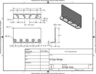
1. PRODUCED BY AN AUTODESK EDUCATIONAL PRODUCT
2 1
3.16
0.45 0.75 0.76 0.75 0.45
B n0.19 B
R0.34
n0.13
PRODUCED BY AN AUTODESK EDUCATIONAL PRODUCT
0.56 0.75 0.75 0.56
0.54 0.08
R0.13
n0.30
1.69
0.20 0.69 0.69 0.69 0.69 0.20 0.08 0.54
DRAWN
Kevin Gills 9/25/2008 ITT Technical Inst.
CHECKED
A TITLE A
QA
MFG B-Style Bridge
APPROVED
SIZE DWG NO REV
A bridge dwg
SCALE
SHEET 1 OF 1
2 1
PRODUCED BY AN AUTODESK EDUCATIONAL PRODUCT