
Recommended
Recommended
More Related Content
Similar to Bobcat a300 all wheel steer loader service repair manual sn 521111001 & above
Similar to Bobcat a300 all wheel steer loader service repair manual sn 521111001 & above (16)
More from jfjskekdhnejd
More from jfjskekdhnejd (20)
Recently uploaded
Recently uploaded (20)
Bobcat a300 all wheel steer loader service repair manual sn 521111001 & above
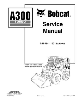
- 1. 6901756 (3-08) Printed in U.S.A. © Bobcat Company 2008 Service Manual S/N 521111001 & Above BOBCAT SKID-STEER LOADER With ALL WHEEL STEER (AWS) EQUIPPED WITH BOBCAT INTERLOCK CONTROL SYSTEM (BICS™)
- 2. A300 Bobcat Loader I Service Manual SPECIFICATIONS CONTENTS FOREWORD. . . . . . . . . . . . . . . . . . . . . . . . . . . . . . . . . . . . . . . . . . . II SAFETY INSTRUCTIONS . . . . . . . . . . . . . . . . . . . . . . . . . . . . . . . . V SERIAL NUMBER LOCATION . . . . . . . . . . . . . . . . . . . . . . . . . . . . .IX DELIVERY REPORT. . . . . . . . . . . . . . . . . . . . . . . . . . . . . . . . . . . . . X BOBCAT LOADER INDENTIFICATION . . . . . . . . . . . . . . . . . . . . . .XI SAFETY AND MAINTENANCE. . . . . . . . . . . . . . . . . . . . . . . . . . 10-01 HYDRAULIC SYSTEM . . . . . . . . . . . . . . . . . . . . . . . . . . . . . . . . 20-01 HYDROSTATIC SYSTEM . . . . . . . . . . . . . . . . . . . . . . . . . . . . . . 30-01 DRIVE SYSTEM . . . . . . . . . . . . . . . . . . . . . . . . . . . . . . . . . . . . . 40-01 MAIN FRAME . . . . . . . . . . . . . . . . . . . . . . . . . . . . . . . . . . . . . . . 50-01 ELECTRICAL SYSTEM & ANALYSIS. . . . . . . . . . . . . . . . . . . . . 60-01 ENGINE SERVICE . . . . . . . . . . . . . . . . . . . . . . . . . . . . . . . . . . . 70-01 SPECIFICATIONS. . . . . . . . . . . . . . . . . . . . . . . . . . . . . . . . . SPEC-01 SAFETY & HYDROSTATIC MAIN FRAME SYSTEM SYSTEM DRIVE ELECTRICAL MAINTENANCE SYSTEM & ANALYSIS ENGINE SERVICE ENGINE SPECIFICATIONS HYDRAULIC SYSTEM
- 3. A300 Bobcat Loader II Service Manual FOREWORD This manual is for the Bobcat loader mechanic. It provides necessary servicing and adjustment procedures for the Bobcat loader and its component parts and systems. Refer to the Operation & Maintenance Manual for operating instructions, Starting procedure, daily checks, etc. A general inspection of the following items must be made after the loader has had service or repair: 1. Check lift arm support device, replace if damaged. (Stored Position) 9. The parking brake must function correctly. 2. Check that ROPS mounting hardware is tightened and is Bobcat approved. 10. Enclosure door latches must open and close freely. 3. The seat belt must be correctly installade, functional and in good condition. 11. Bob-Tach wedges and linkages must function correctly and be in good condition. 4. The seat bar must be correctly adjusted, clean and lubricated. 12. Safety treads must be in good condition. 5. Check lift arm support device, replace if damaged. 13. Check for correct function of indicator lamps (Optional on some models. 6. Machine signs must be legible and in the correct location. 14. Check hydraulic fluid level, engine oil level and fuel supply. 7. Steering levers and foot pedals must return to neutral. 15. Inspect for fuel, oil or hydraulic fluid leaks. 8. Check for correct function of the work lights 16. Lubricate the loader.
- 4. A300 Bobcat Loader III Service Manual 17. Check the condition of the battery and cables. 22. Operate the loader and check all functions. 18. Inspect the air cleaner for damage or leaks. Check the condition of the element. 23. Check for any field modification not completed. 19. Check the electrical charging system. 24. Check for correct function of the Bobcat Interlock Control System (BICS™) before the machine is returned to the customer. 20. Check tires for wear and pressure. Recommend to the owner that all necessary corrections be made before the machine is returned to service. 21. Inspect for loosen or broken parts or connections. CALIFORNIA PROPOSITION 65 WARNING Diesel engine exhaust and some of its constituents are known to the State of California to cause cancer, birth defects and other reproductive harm.
- 5. A300 Bobcat Loader V Service Manual SAFETY INSTRUCTIONS WARNING Instructions are necessary before operating or servicing machine. Read and understand the Operation & Maintenance Manual, Operator’s Handbook and signs (decals) on machine. Follow warnings and instructions in the manuals when making repairs, adjustments or servicing. Check for correct function after adjustments, repairs or service. Untrained operators and failure to follow instructions can cause injury or death. W-2003-0903 WARNING Warnings on the machine and in the manuals are for your safety. Failure to obey warnings can cause injury or death. W-2044-1285 IMPORTANT This notice identifies procedures which must be followed to avoid damage to the machine. I-2019-0284 The following publications provide information on the safe use and maintenance of the Bobcat machine and attachments: • The Delivery Report is used to assure that complete instructions have been given to the new owner and that the machine is in safe operating condition. • The Operation & Maintenance Manual delivered with the machine or attachment contains operating information as well as routine maintenance and service procedures. It is a part of the machine and can be stored in a container provided on the machine. Replacement Operation & Maintenance Manuals can be ordered from your Bobcat dealer. • Machine signs (decals) instruct on the safe operation and care of your Bobcat machine or attachment. The signs and their locations are shown in the Operation & Maintenance Manual. Replacement signs are available from your Bobcat dealer. • An Operator’s Handbook fastened to the operator cab. It’s brief instructions are convenient to the operator. The handbook is available from your dealer in an English edition or one of many other languages. See your Bobcat dealer for more information on translated versions. • The AEM Safety Manual delivered with the machine gives general safety information. • The Service Manual and Parts Manual are available from your dealer for use by mechanics to do shop- type service and repair work. • The Skid-Steer Loader Operator Training Course is available through your local dealer or at www.training.bobcat.com or www.bobcat.com. This course is intended to provide rules and practices of correct operation of the Skid-Steer Loader. The course is available in English and Spanish versions. • Service Safety Training Courses are available from your Bobcat dealer or at www.training.bobcat.com or www.bobcat.com. They provide information for safe and correct service procedures. • The Skid-Steer Loader Safety Video is available from your Bobcat dealer or at www.training.bobcat.com or www.bobcat.com. SI SSL-0206 SM This symbol with a warning statement means: “Warning, be alert! Your safety is involved!” Carefully read the message that follows. Safety Alert Symbol
- 6. A300 Bobcat Loader VII Service Manual SAFETY INSTRUCTIONS (CONT’D) Fire Prevention The machine and attachments have components that are at high temperature under normal operating conditions. The primary source of high temperatures is the engine and exhaust system. The electrical system, if damaged or incorrectly maintained, can be a source of arcs or sparks. Flammable debris (leaves, straw, etc.) must be removed regularly. If flammable debris is allowed to accumulate, it will increase fire hazard. Clean often to avoid this accumulation. Flammable debris in the engine compartment is a potential hazard. The spark arrestor muffler is designed to control the emission of hot particles from the engine and exhaust system, but the muffler and the exhaust gases are still hot. • Do not use the machine where exhaust, arcs, sparks or hot components can contact flammable material, explosive dust or gases. • The operator cab, engine compartment, and engine cooling system must be inspected every day and cleaned if necessary to prevent fire hazard and overheating. • Check all electrical wiring and connections for damage. Keep the battery terminals clean and tight. Repair or replace any damaged part. • Check fuel and hydraulic tubes, hoses and fittings for damage and leakage. Never use open flame or bare skin to check for leaks. Tighten or replace any parts that show leakage. Always clean fluid spills. Do not use gasoline or diesel fuel for cleaning parts. Use commercial nonflammable solvents. • Do not use ether or starting fluids on any engine which has glow plugs. These starting aids can cause explosion and injure you or bystanders. • Always clean the machine, disconnect the battery, and disconnect the wiring from the controllers before welding. Cover rubber hoses, battery and all other flammable parts. Keep a fire extinguisher near the machine when welding. Have good ventilation when grinding or welding painted parts. Wear a dust mask when grinding painted parts. Toxic dust or gas can be produced. • Stop the engine and let it cool before adding fuel. NO SMOKING! • Use the procedure in the Operation & Maintenance Manual for connecting the battery and for jump starting. • Use the procedure in the Operation & Maintenance Manual for cleaning the spark arrestor muffler (if equipped). Figure 1 • Know where fire extinguishers and first aid kits are located and how to use them. Fire extinguishers are available from your Bobcat dealer [Figure 1]. SI SSL-0206 SM
- 7. A300 Bobcat Loader IX Service Manual SERIAL NUMBER LOCATION Always use the serial number of the loader when requesting service information or when ordering parts. Early or later models (identification made by serial number) may use different parts, or it may be necessary to use a different procedure in doing a specific service operation. Loader Serial Number Figure 2 The loader serial number plate is located on the outside of the loader frame [Figure 2]. Explanation of loader Serial Number: 1. The four digit Model/Engine Combination Module number identifies the model number and engine combination. 2. The five digit Production Sequence Number identifies the order which the loader is produced. Engine Serial Number Figure 3 Figure 4 The engine serial number is located on the valve cover at the right side of the engine [Figure 3]. There is also an extra S/N tag attached to the engine [Figure 4] XXXX XXXXX Model 1.-Model/ Engine Combination Model 2.-Production Sequence (Series) N-19358 P-24798 P-24799
- 8. A300 Bobcat Loader X Service Manual DELIVERY REPORT Figure 5 The Delivery Report must be filled out by the dealer and signed by the owner or operator when the Bobcat loader is delivered. An explanation of the form must be given to the owner. Make sure it is filled out completely [Figure 5]. B-16315
- 9. A300 Bobcat Loader XI Service Manual BOBCAT LOADER INDENTIFICATION ▼REAR AUXILIARY QUICK COUPLERS ▼ FRONT LIGHTS TILT CYLINDER + BUCKET ● OPERATOR CAB (ROPS & FOPS) LIFT ARM * TIRES ▼ TAIL LIGHT REAR DOOR ▼REAR LIGHT REAR GRILL LIFT ARM SUPPORT DEVICE SEAT BAR LIFT CYLINDER BUCKET STEPS B-16375 GRAB HANDLES STEPS OPERATOR SEAT with SEAT BELT B-16374 STEERING LEVER ▼FRONT AUXILIARY QUICK COUPLERS ▼ OPTIONAL OR FIELD ACCESSORY (Not Standard Equipment) * TIRES - Flotation tires ▼ are shown. The Bobcat loader is factory equipped with standard tires. + BUCKET - Several different buckets and other attachments are available for the Bobcat loader. ● ROPS, FOPS - Roll Over Protective Structure, per SAE J1040 and ISO 3471, and Falling Object Protective Structure per SAEJ1043 and ISO 3449, Level I. Level II is available. The Bobcat loader is base-equipped with a standard operator cab as shown. Extra insulated cab is available as an option (Reduced noise level).
- 10. A300 Bobcat Loader 10-01 Service Manual SAFETY AND MAINTENANCE AIR CLEANER SERVICE . . . . . . . . . . . . . . . . . . . . . . . . . . . . 10-80-1 Replacing Filter Element . . . . . . . . . . . . . . . . . . . . . . . . . . 10-80-1 BOB-TACH . . . . . . . . . . . . . . . . . . . . . . . . . . . . . . . . . . . . . . 10-150-1 Inspection And Maintenance . . . . . . . . . . . . . . . . . . . . . . 10-150-1 ENGINE COOLING SYSTEM . . . . . . . . . . . . . . . . . . . . . . . . . 10-90-1 Cleaning Cooling System. . . . . . . . . . . . . . . . . . . . . . . . . . 10-90-1 ENGINE LUBRICATION SYSTEM . . . . . . . . . . . . . . . . . . . . 10-110-1 Checking Engine Oil . . . . . . . . . . . . . . . . . . . . . . . . . . . . 10-110-1 Oil Chart. . . . . . . . . . . . . . . . . . . . . . . . . . . . . . . . . . . . . . 10-110-1 Replacing Oil And Filter . . . . . . . . . . . . . . . . . . . . . . . . . . 10-110-1 FAN GEARBOX. . . . . . . . . . . . . . . . . . . . . . . . . . . . . . . . . . . 10-140-1 Checking And Adding Oil. . . . . . . . . . . . . . . . . . . . . . . . . 10-140-1 FINAL DRIVE TRANSMISSION (CHAINCASE) . . . . . . . . . . 10-130-1 Checking And Adding Oil. . . . . . . . . . . . . . . . . . . . . . . . . 10-130-1 Replacing The Oil . . . . . . . . . . . . . . . . . . . . . . . . . . . . . . 10-130-1 FUEL SYSTEM . . . . . . . . . . . . . . . . . . . . . . . . . . . . . . . . . . . 10-100-1 Filling The Fuel Tank . . . . . . . . . . . . . . . . . . . . . . . . . . . . 10-100-1 Fuel Filter. . . . . . . . . . . . . . . . . . . . . . . . . . . . . . . . . . . . . 10-100-1 Fuel Lift Pump Strainer . . . . . . . . . . . . . . . . . . . . . . . . . . 10-100-2 Fuel Specifications. . . . . . . . . . . . . . . . . . . . . . . . . . . . . . 10-100-1 Removing Air From The Fuel System . . . . . . . . . . . . . . . 10-100-2 HYDRAULIC/HYDROSTATIC SYSTEM . . . . . . . . . . . . . . . . 10-120-1 Checking And Adding Fluid . . . . . . . . . . . . . . . . . . . . . . . 10-120-1 Hydraulic/Hydrostatic Filter Replacement . . . . . . . . . . . . 10-120-1 Replacing Hydraulic Fluid . . . . . . . . . . . . . . . . . . . . . . . . 10-120-2 Steering Filter Replacement . . . . . . . . . . . . . . . . . . . . . . 10-120-2 LIFT ARM SUPPORT DEVICE . . . . . . . . . . . . . . . . . . . . . . . . 10-20-1 Installing The Lift Arm Support Device. . . . . . . . . . . . . . . . 10-20-1 Removing The Lift Arm Support Device. . . . . . . . . . . . . . . 10-20-2 LIFTING AND BLOCKING THE LOADER . . . . . . . . . . . . . . . 10-10-1 Procedure . . . . . . . . . . . . . . . . . . . . . . . . . . . . . . . . . . . . . 10-10-1 LUBRICATING THE LOADER . . . . . . . . . . . . . . . . . . . . . . . 10-160-1 Procedure . . . . . . . . . . . . . . . . . . . . . . . . . . . . . . . . . . . . 10-160-1 Continued On Next Page SAFETY & SYSTEM DRIVE ELECTRICAL MAINTENANCE SYSTEM & ANALYSIS ENGINE SERVICE SPECIFICATIONS
- 11. A300 Bobcat Loader 10-02 Service Manual SAFETY AND MAINTENANCE (CONT’D) OPERATOR CAB . . . . . . . . . . . . . . . . . . . . . . . . . . . . . . . . . . 10-30-1 Description. . . . . . . . . . . . . . . . . . . . . . . . . . . . . . . . . . . . . 10-30-1 Emergency Exit . . . . . . . . . . . . . . . . . . . . . . . . . . . . . . . . . 10-30-2 Lowering The Operator Cab . . . . . . . . . . . . . . . . . . . . . . . 10-30-2 Raising The Operator Cab. . . . . . . . . . . . . . . . . . . . . . . . . 10-30-1 POWER BOB-TACH . . . . . . . . . . . . . . . . . . . . . . . . . . . . . . . 10-151-1 Inspection And Maintenance . . . . . . . . . . . . . . . . . . . . . . 10-151-1 REMOTE START. . . . . . . . . . . . . . . . . . . . . . . . . . . . . . . . . . . 10-60-1 Procedure . . . . . . . . . . . . . . . . . . . . . . . . . . . . . . . . . . . . . 10-60-3 Procedure For Loader With Attachments Control Harness 10-60-2 Procedure For Loader W/O Attachments Control Harness 10-60-1 SERVICE SCHEDULE . . . . . . . . . . . . . . . . . . . . . . . . . . . . . . 10-70-1 Chart . . . . . . . . . . . . . . . . . . . . . . . . . . . . . . . . . . . . . . . . . 10-70-1 TIRE MAINTENANCE. . . . . . . . . . . . . . . . . . . . . . . . . . . . . . 10-170-1 Tire Mounting . . . . . . . . . . . . . . . . . . . . . . . . . . . . . . . . . . 10-170-1 Tire Rotation. . . . . . . . . . . . . . . . . . . . . . . . . . . . . . . . . . . 10-170-1 Wheel Nuts . . . . . . . . . . . . . . . . . . . . . . . . . . . . . . . . . . . 10-170-1 TOWING THE LOADER . . . . . . . . . . . . . . . . . . . . . . . . . . . . . 10-50-1 Procedure . . . . . . . . . . . . . . . . . . . . . . . . . . . . . . . . . . . . . 10-50-1 TRANSPORTING THE BOBCAT LOADER . . . . . . . . . . . . . . 10-40-1 Procedure . . . . . . . . . . . . . . . . . . . . . . . . . . . . . . . . . . . . . 10-40-1
- 12. Thank you very much for your reading. Please Click Here. Then Get COMPLETE MANUAL. NO WAITING NOTE: If there is no response to click on the link above, please download the PDF document first and then click on it.
- 13. A300 Bobcat Loader 10-10-1 Service Manual LIFTING AND BLOCKING THE LOADER Procedure Figure 10-10-1 WARNING Instructions are necessary before operating or servicing machine. Read and understand the Operation & Maintenance Manual, Operator’s Handbook and signs (decals) on machine. Follow warnings and instructions in the manuals when making repairs, adjustments or servicing. Check for correct function after adjustments, repairs or service. Untrained operators and failure to follow instructions can cause injury or death. W-2003-0903 Read the Removal & Installation, Disassembly & Assembly, etc. completely to become familiar with the procedure before beginning [Figure 10-10-1]. Always park the loader on a level surface. WARNING Put jackstands under the front axles and rear corners of the frame before running the engine for service. Failure to use jackstands can allow the machine to fall or move and cause injury or death. W-2017-0286 Figure 10-10-2 Lift the rear of the loader and install jackstands [Figure 10-10-2]. Figure 10-10-3 Lift the front of the loader and put jackstands under the axle tubes [Figure 10-10-3]. NOTE: Make sure the jackstands do not touch the tires. B-7023A P-31290 P-31677
- 14. A300 Bobcat Loader 10-20-1 Service Manual LIFT ARM SUPPORT DEVICE Installing The Lift Arm Support Device Figure 10-20-1 WARNING Never work on a machine with the lift arms up unless the lift arms are secured by an approved lift arm support device. Failure to use an approved lift arm support device can allow the lift arms or attachment to fall and cause injury or death. W-2059-0598 WARNING Service lift arm support device if damaged or if parts are missing. Using a damaged lift arm support or with missing parts can cause lift arms to drop causing injury or death. W-2271-1197 Put jackstands under the rear corners of the loader frame (Inset) [Figure 10-20-1]. Remove the lift arm support device (Item 1) [Figure 10- 20-1] from the storage position. The operator must stay in the operator seat with the seat belt fastened and the seat bar lowered, until the lift arm support device is installed. Start the engine and raise the lift arms all the way up. Figure 10-20-2 Have a second person install the lift arm support device over the rod of one of the lift cylinders [Figure 10-20-2]. The lift arm support device must be tight against the cylinder rod. The tabs of the lift arm support device must be under the cylinder as shown (Inset) [Figure 10-20-2]. P-31244 P-31290 1 P-31264 P-10136
- 15. A300 Bobcat Loader 10-20-2 Service Manual LIFT ARM SUPPORT DEVICE (CONT’D) Installing The Lift Arm Support Device (Cont’d) Figure 10-20-3 Lower the lift arms slowly until the lift arm support device is held between the lift arms and lift cylinder [Figure 10- 20-3]. Removing The Lift Arm Support Device The operator must be in the operator's seat, with the seat belt fastened and seat bar lowered, until the lift arm support device is removed and the lift arms are lowered all the way. Start the engine, raise the lift arms all the way up. Have a second person remove the lift arm support device. Lower the lift arms all the way and stop the engine. Return the lift arm support device to storage position and secure with clamping knobs. Remove the jackstands. P-31265
- 16. A300 Bobcat Loader 10-30-1 Service Manual OPERATOR CAB Description The Bobcat loader has an operator cab (ROPS and FOPS) as standard equipment to protect the operator from rollover and falling objects. Check with your dealer if the operator cab has been damaged. The seat belt must be worn for roll over protection. ROPS/FOPS - Roll Over Protective Structure per SAE J1040 and ISO 3471, and Falling Object Protective Structure per SAE J1043 and ISO 3449, Level I. Level II is available. Level I - Protection from falling bricks, small concrete blocks, and hand tools encountered in operations such as highway maintenance, landscaping, and other construction site services. Level II - Protection from falling trees, rocks; for machines involved in site clearing, overhead demolition or forestry. Raising The Operator Cab Figure 10-30-1 Always stop the engine before raising or lowering the cab. Stop the loader on a level surface. Lower the lift arms. If the lift arms must be up while raising the operator cab, install the lift arm support device. (See Installing The Lift Arm Support Device on Page 10-20-1.) Install jackstands under the rear of the loader frame [Figure 10-30-1]. Figure 10-30-2 Loosen the nut (both sides) at the front corner of the operator cab [Figure 10-30-2]. Remove the nuts and plates [Figure 10-30-2] (both sides). Figure 10-30-3 Lift on the grab handle and bottom of the operator cab slowly until the cab is all the way up and the latching mechanism engages [Figure 10-30-3]. P-31290 P-31289 P-31288 P-31267
- 17. A300 Bobcat Loader 10-30-2 Service Manual OPERATOR CAB (CONT’D) Raising The Operator Cab (Cont’d) Advanced Hand Control Only WARNING Never modify operator cab by welding, grinding, drilling holes or adding attachments unless instructed to do so by Bobcat. Changes to the cab can cause loss of operator protection from rollover and falling objects, and result in injury or death. W-2069-1299 Lowering The Operator Cab Figure 10-30-4 Always stop the engine before raising or lowering the cab. NOTE: Make sure the seat bar is fully raised or lowered when lowering the cab. Always use the grab handles to lower the cab. Pull down on the bottom of the operator cab until it stops at the latching mechanism [Figure 10-30-4]. Release the latching mechanism (Inset) [Figure 10-30-4] and pull the cab all the way down. Figure 10-30-5 Install the plates and nuts [Figure 10-30-5] (both sides). Tighten the nuts to 40-50 ft.-lb. (54-68 N•m) torque. Emergency Exit Figure 10-30-6 The front opening on the operator cab and rear window provide exits. REAR WINDOW (If Equipped) Pull on the tag on the top of the rear window to remove the rubber cord [Figure 10-30-6]. P-31268 N-20120 P-31289 P-31288 N-19386