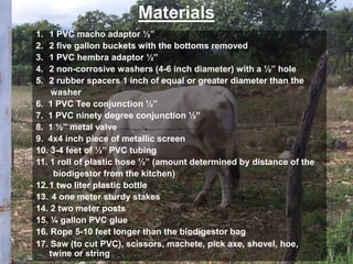
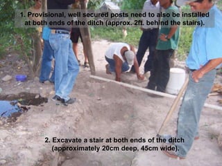
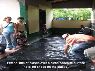
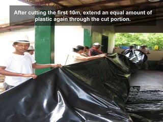
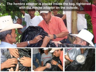
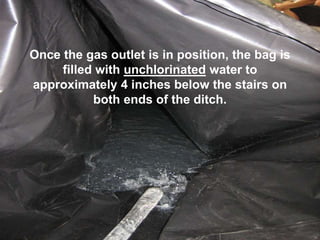
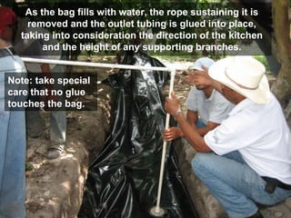
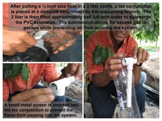
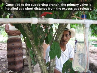
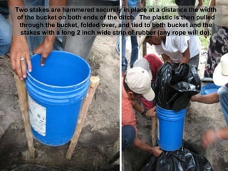
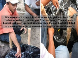
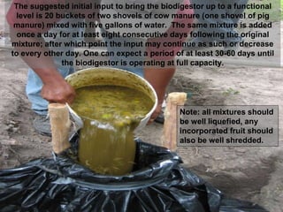
BIODIGESTORES
Materials
1. 1 PVC macho adaptor ½”
2. 2 five gallon buckets with the bottoms removed
3. 1 PVC hembra adaptor ½”
4. 2 non-corrosive washers (4-6 inch diameter) with a ½” hole
5. 2 rubber spacers 1 inch of equal or greater diameter than the
washer
6. 1 PVC Tee conjunction ½”
7. 1 PVC ninety degree conjunction ½”
8. 1 ½” metal valve
9. 4x4 inch piece of metallic screen
10. 3-4 feet of ½” PVC tubing
11. 1 roll of plastic hose ½” (amount determined by distance of the
biodigestor from the kitchen)
12.1 two liter plastic bottle
13. 4 one meter sturdy stakes
14. 2 two meter posts
15. ¼ gallon PVC glue
16. Rope 5-10 feet longer than the biodigestor bag
17. Saw (to cut PVC), scissors, machete, pick axe, shovel, hoe,
twine or string
SIGHT PREPERATION
A ditch 8m x 1m x 60cm with an approximate
difference of 5cm from entrance to exit
(ditch dimensions will vary according to plastic)
Clear ditch of any debris that could puncture
the plastic.
Walls of ditch spackled with mud to cover
protruding root ends.
2. Excavate a stair at both ends of the ditch
(approximately 20cm deep, 45cm wide).
(1. Provisional, well secured posts need to also be installed
at both ends of the ditch (approx. 2ft. behind the stairs).
Extend 10m of plastic over a clean concrete surface
(note: no shoes on the plastic).
After cutting the first 10m, extend an equal amount of
plastic again through the cut portion.
After extending the second portion, take care to align
the two bags so as to avoid any folds or bunching.
Once the two bags are aligned, extend a rope
(approximately 15m) through the double bag and tie it
off at the secured posts on both ends of the ditch so as
to leave the bag hanging, however, touching the
ground.
Once the bag is in place the gas outlet can be installed.
You’ll need two non-corrosive palm size washers, and
two rubber spacers of equal or greater size.
Insert a ½ inch PVC hembra adaptor with the rubber
spacer on top of the non-corrosive washer, and
likewise with the ½ inch PVC macho adaptor.
The location of the gas outlet will depend largely on the general
surroundings of the ditch. The hole does not need to be in the
middle of the bag, it can be placed towards one end or another so
as to take advantage of hanging branches for the outlet’s support.
If there are no surrounding branches to support the outlet tubing, a
post may be installed to serve the same purpose.
Once the location has been chosen,
make a small cut, no bigger than a
½ inch, through the double bag.
The hembra adaptor is placed inside the bag, tightened
with the macho adaptor on the outside.
Once the gas outlet is in position, the bag is
filled with unchlorinated water to
approximately 4 inches below the stairs on
both ends of the ditch.
As the bag fills with water, the rope sustaining it is
removed and the outlet tubing is glued into place,
taking into consideration the direction of the kitchen
and the height of any supporting branches.
Note: take special
care that no glue
touches the bag.
After cutting a ½ inch size hole in a 2 liter bottle, a tee conjunction
is placed at a distance determined by the supporting branch. The
2 liter is then filled approximately half full with water to submerge
the PVC extension. The submersion allows for excess gas to
escape while preventing air from entering the system.
A small metal screen is inserted into
the tee conjunction to prevent the
flame from passing into the system.
Once tied to the supporting branch, the primary valve is
installed at a short distance from the excess gas release.
Two stakes are hammered securely in place at a distance the width
of the bucket on both ends of the ditch. The plastic is then pulled
through the bucket, folded over, and tied to both bucket and the
stakes with a long 2 inch wide strip of rubber (any rope will do).
It is essential that each bucket be submerged in at least 3-4
inches of water to prevent gas from escaping. The entrance
bucket rest in an up-right position while the exit bucket is tilted
at a 45 degree angle to allow the passage of excess liquids.
The suggested initial input to bring the biodigestor up to a functional
level is 20 buckets of two shovels of cow manure (one shovel of pig
manure) mixed with five gallons of water. The same mixture is added
once a day for at least eight consecutive days following the original
mixture; after which point the input may continue as such or decrease
to every other day. One can expect a period of at least 30-60 days until
the biodigestor is operating at full capacity.
Note: all mixtures should
be well liquefied, any
incorporated fruit should
also be well shredded.
In the Kitchen
Two valves are secured to the stove, then depending
upon the placement of the stove and the direction of
the incoming tubing, a 90 degree and tee conjunction
are placed accordingly.
A small piece of PVC is measured and
cut to bridge the two conjunctions.
To avoid reaching across an open flame to
close the valves, recommended valve
placement is between the burner and the stove
operator.
¡Buen Provecho!

Biodigestores revised

  • 1.
  • 2.
    Materials 1. 1 PVCmacho adaptor ½” 2. 2 five gallon buckets with the bottoms removed 3. 1 PVC hembra adaptor ½” 4. 2 non-corrosive washers (4-6 inch diameter) with a ½” hole 5. 2 rubber spacers 1 inch of equal or greater diameter than the washer 6. 1 PVC Tee conjunction ½” 7. 1 PVC ninety degree conjunction ½” 8. 1 ½” metal valve 9. 4x4 inch piece of metallic screen 10. 3-4 feet of ½” PVC tubing 11. 1 roll of plastic hose ½” (amount determined by distance of the biodigestor from the kitchen) 12.1 two liter plastic bottle 13. 4 one meter sturdy stakes 14. 2 two meter posts 15. ¼ gallon PVC glue 16. Rope 5-10 feet longer than the biodigestor bag 17. Saw (to cut PVC), scissors, machete, pick axe, shovel, hoe, twine or string
  • 3.
    SIGHT PREPERATION A ditch8m x 1m x 60cm with an approximate difference of 5cm from entrance to exit (ditch dimensions will vary according to plastic)
  • 4.
    Clear ditch ofany debris that could puncture the plastic.
  • 5.
    Walls of ditchspackled with mud to cover protruding root ends.
  • 6.
    2. Excavate astair at both ends of the ditch (approximately 20cm deep, 45cm wide). (1. Provisional, well secured posts need to also be installed at both ends of the ditch (approx. 2ft. behind the stairs).
  • 7.
    Extend 10m ofplastic over a clean concrete surface (note: no shoes on the plastic).
  • 8.
    After cutting thefirst 10m, extend an equal amount of plastic again through the cut portion.
  • 9.
    After extending thesecond portion, take care to align the two bags so as to avoid any folds or bunching.
  • 10.
    Once the twobags are aligned, extend a rope (approximately 15m) through the double bag and tie it off at the secured posts on both ends of the ditch so as to leave the bag hanging, however, touching the ground.
  • 11.
    Once the bagis in place the gas outlet can be installed. You’ll need two non-corrosive palm size washers, and two rubber spacers of equal or greater size.
  • 12.
    Insert a ½inch PVC hembra adaptor with the rubber spacer on top of the non-corrosive washer, and likewise with the ½ inch PVC macho adaptor.
  • 13.
    The location ofthe gas outlet will depend largely on the general surroundings of the ditch. The hole does not need to be in the middle of the bag, it can be placed towards one end or another so as to take advantage of hanging branches for the outlet’s support. If there are no surrounding branches to support the outlet tubing, a post may be installed to serve the same purpose. Once the location has been chosen, make a small cut, no bigger than a ½ inch, through the double bag.
  • 14.
    The hembra adaptoris placed inside the bag, tightened with the macho adaptor on the outside.
  • 15.
    Once the gasoutlet is in position, the bag is filled with unchlorinated water to approximately 4 inches below the stairs on both ends of the ditch.
  • 16.
    As the bagfills with water, the rope sustaining it is removed and the outlet tubing is glued into place, taking into consideration the direction of the kitchen and the height of any supporting branches. Note: take special care that no glue touches the bag.
  • 17.
    After cutting a½ inch size hole in a 2 liter bottle, a tee conjunction is placed at a distance determined by the supporting branch. The 2 liter is then filled approximately half full with water to submerge the PVC extension. The submersion allows for excess gas to escape while preventing air from entering the system. A small metal screen is inserted into the tee conjunction to prevent the flame from passing into the system.
  • 18.
    Once tied tothe supporting branch, the primary valve is installed at a short distance from the excess gas release.
  • 19.
    Two stakes arehammered securely in place at a distance the width of the bucket on both ends of the ditch. The plastic is then pulled through the bucket, folded over, and tied to both bucket and the stakes with a long 2 inch wide strip of rubber (any rope will do).
  • 20.
    It is essentialthat each bucket be submerged in at least 3-4 inches of water to prevent gas from escaping. The entrance bucket rest in an up-right position while the exit bucket is tilted at a 45 degree angle to allow the passage of excess liquids.
  • 21.
    The suggested initialinput to bring the biodigestor up to a functional level is 20 buckets of two shovels of cow manure (one shovel of pig manure) mixed with five gallons of water. The same mixture is added once a day for at least eight consecutive days following the original mixture; after which point the input may continue as such or decrease to every other day. One can expect a period of at least 30-60 days until the biodigestor is operating at full capacity. Note: all mixtures should be well liquefied, any incorporated fruit should also be well shredded.
  • 22.
  • 23.
    Two valves aresecured to the stove, then depending upon the placement of the stove and the direction of the incoming tubing, a 90 degree and tee conjunction are placed accordingly.
  • 24.
    A small pieceof PVC is measured and cut to bridge the two conjunctions.
  • 25.
    To avoid reachingacross an open flame to close the valves, recommended valve placement is between the burner and the stove operator.
  • 26.