Download to read offline
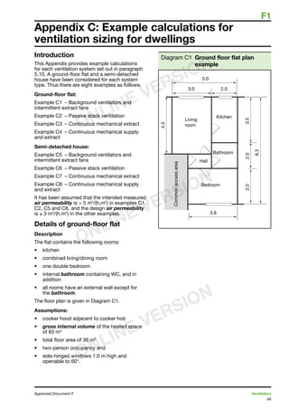
![F1
41
Approved Document F Ventilation
Section 8: Standards and other publications
Standards
BS EN 378-3:2008 Refrigerating systems
and heat pumps. Safety and environmental
requirements. Installation site and personal
protection.
BSI PD CR 1752:1999 Ventilation for buildings –
design criteria for the indoor environment.
BS 5502:2003 Buildings and structures for
agriculture. Various relevant parts including: Part
33:1991 Guide to the control of odour pollution,
AMD 10014 1998. Part 52:1991 Code of
practice for design of alarm systems, emergency
ventilation and smoke ventilation for livestock
housing, AMD 10014 1998.
BS 5454:2000 Recommendations for the storage
and exhibition of archival documents.
BS 5925:1991 Code of practice for ventilation
principles and designing for natural ventilation.
AMD 8930 1995.
BS 7913:1998 Principles of the conservation of
historic buildings.
BS EN 13141-1:2004 Ventilation for buildings.
Performance testing of components/products for
residential ventilation. Externally and internally
mounted air transfer devices.
BS EN 13141-3:2004 Ventilation for buildings.
Performance testing of components/products for
residential ventilation. Range hoods for residential
use.
BS EN 13141-4:2004 Ventilation for buildings.
Performance testing of components/products for
residential ventilation. Fans used in residential
ventilation systems.
BS EN 13141-6:2004 Ventilation for buildings.
Performance testing of components/products for
residential ventilation. Exhaust ventilation system
packages used in a single dwelling.
BS EN 13141-7:2004 Ventilation for buildings.
Performance testing of components/products
for residential ventilation. Performance testing
of a mechanical supply and exhaust ventilation
units (including heat recovery) for mechanical
ventilation systems intended for single family
dwellings.
BS EN 13141-8:2006 Ventilation for buildings.
Performance testing of components/products
for residential ventilation. Performance testing
of unducted mechanical supply and exhaust
ventilation units [including heat recovery] for
mechanical ventilation systems intended for a
single room.
BS EN 13986:2004 Wood-based panels for use
in construction. Characteristics, evaluation of
conformity and marking.
Other publications
American Conference of Government
Industrial Hygienists (ACGIH)
Industrial ventilation 26th Edition, Manual of
recommended practice.
Available from: www.acgih.org/store
BRE
BRE Digest 464, Part 1: VOC emissions from
building products. Sources, testing and emission
data, 2002. ISBN 978 1 86081 546 1.
BRE Digest 464, Part 2: VOC emissions from
building products. Control, evaluation and
labelling schemes, 2002. ISBN 978 1 86081 547 8.
BSRIA
Ventilation hygiene toolkit:
BSRIA Facilities Management Specification
1 Guidance to the standard specification for
ventilation hygiene, 2002. ISBN 978 0 86022 454 9.
Chartered Institution of Building Services
Engineers (CIBSE)
Applications Manual AM10: Natural ventilation in
non-domestic buildings, 2005.
ISBN 978 1 80328 756 0.
Applications Manual AM13: Mixed mode
ventilation, 2000. ISBN 978 1 90328 701 4.
CIBSE Guide A: Environmental design, 2006.
ISBN 978 1 90328 766 8.
CIBSE Guide B: Heating, ventilating, air
conditioning and refrigeration, 2005.
ISBN 978 1 90328 758 3.
TM13: Minimising the risk of Legionnaires’
disease, 2002. ISBN 978 1 90328 723 1.
CIBSE Commissioning Codes, available from:
www.cibse.org/index.cfm?go=publications.
viewitem=266.
CIBSE TM26 Hygienic maintenance of office
ventilation ductwork, 2000.
ISBN 978 1 90328 711 8.
Defence Estates
Defence Works Functional Standard, Design and
Maintenance Guide 08: Space requirements for
plant access operation and maintenance, 1996.
ISBN 978 1 11772 785 4. Available from:
www.defence-estates.mod.uk/publications/
dmg/dmg_08.pdf
Department for Children, Schools and
Families (DCSF);
Building Bulletin 101, Ventilation of school
buildings, 2006. ISBN 978 0 11271 164 3.
See: www.teachernet.gov.uk/iaq
ONLINE VERSION
ONLINE VERSION
ONLINE VERSION](https://image.slidesharecdn.com/bestupvcslidingsashwindow-150611120439-lva1-app6891/85/Best-uPVC-sliding-sash-window-46-320.jpg)

The document outlines the 2010 edition of the Approved Document F, which details the ventilation requirements in buildings, replacing the 2006 edition. Key changes include mandatory commissioning of mechanical ventilation systems, increased ventilation provisions for highly air-permeable dwellings, and clarified guidance for kitchen and bathroom refurbishments. It also lists amendments to the building regulations and provides practical guidance for compliance.