Download to read offline
![International Journal of Mechanical Engineering and Technology (IJMET), ISSN 0976 – 6340(Print),
ISSN 0976 – 6359(Online), Volume 5, Issue 9, September (2014), pp. 306-314 © IAEME
306
BEND-TWIST COUPLING AND ITS EFFECT ON CAVITATION INCEPTION
OF COMPOSITE MARINE PROPELLER
S. Solomon Raj1
, Dr. P.Ravinder Reddy2
1, 2
Department of Mechanical Engineering, Chaitanya Bharathi Institute of Technology,
Hyderabad-75, India
ABSTRACT
Cavitation in marine propellers has adverse effects such as noise, erosion and vibrations
which result in loss of lift and increase in drag. The radiated noise level of any form of cavitation is
of the order of magnitude higher than the noise level of non-cavitating flow. This is used by navy
ships to detect and locate other ships. Cavitation has to be discouraged from stealth point of view.
Generally marine propellers are made with NAB. The NAB propeller can be replaced with the
composite propeller which has intrinsic bend-twist coupling for performance enhancement. In this
work, the bend-twist coupling effects are used for designing the composite propeller, which replaces
the NAB propeller for increased operating range with regard to cavitation inception. Fluid structure
interaction (FSI) is carried out using the commercially available numerical codes FLUENT, ANSYS
and HYPERMESH. Experiments are carried out in cavitation tunnel to validate the numerical model.
The results showed that stacking sequence for the composite propeller can be selected to give
enhanced performance range when compared to metallic propeller from cavitation point of view.
Keywords: Bend-Twist Coupling, Cavitation Inception, Composite, Propeller.
I. INTRODUCTION
The propeller is that component of the ship which converts the engine power into the driving
force of the ship. These days, conventional marine propellers remain the standard propulsion
mechanism for surface ships and underwater vehicles. Composite materials have been fully
established as workable engineering materials and are now commonly used for many engineering
applications requiring high strength-to-weight and stiffness-to-weight ratios [1]. Traditional
propellers are made of high-stiffness metal materials such as nickel-aluminum-bronze (NAB) or
manganese bronze (MB). Rotors made of metallic alloys are typically designed to behave as rotating
rigid blades, and achieve the optimal performance at the design operating condition. When the
INTERNATIONAL JOURNAL OF MECHANICAL ENGINEERING
AND TECHNOLOGY (IJMET)
ISSN 0976 – 6340 (Print)
ISSN 0976 – 6359 (Online)
Volume 5, Issue 9, September (2014), pp. 306-314
© IAEME: www.iaeme.com/IJMET.asp
Journal Impact Factor (2014): 7.5377 (Calculated by GISI)
www.jifactor.com
IJMET
© I A E M E](https://image.slidesharecdn.com/bend-twist-coupling-and-its-effect-on-cavitation-inception-of-composite-marine-propeller-160218105350/75/BEND-TWIST-COUPLING-AND-ITS-EFFECT-ON-CAVITATION-INCEPTION-OF-COMPOSITE-MARINE-PROPELLER-1-2048.jpg)
![International Journal of Mechanical Engineering and Technology (IJMET), ISSN 0976 – 6340(Print),
ISSN 0976 – 6359(Online), Volume 5, Issue 9, September (2014), pp. 306-314 © IAEME
307
operating condition changes from the design values, the blade geometry becomes sub-optimal
relative to the changed in flow. Consequently, the rotor efficiency decreases, and the rotor may be
subjected to strength, vibration and stability issues. The effect is more severe when a rotor is
operating in a spatially or temporally varying inflow. Fiber-reinforced composites are extensively
applied in various structures such as aerospace, renewable energy, and marine applications, because
of its light weight, high strength and corrosion resistance, better fatigue characteristics, lower life-
cycle costs.
Cavitation occurs when the local absolute pressure is less than local vapor pressure for the
fluid medium. In fluid power applications the evaporation pressure is reached when flow velocity is
increased sufficiently. Cavitation may lead to expensive problems if not acknowledged in an early
design stage. The inception of cavitation on hydrofoil is a basic phenomenon in hydrodynamics
which refers to the appearance of vapor phase when liquid flows around a hydrofoil. For thin
hydrofoils at moderate angle of attack, the first occurrence of cavitation is closely related to the
minimum pressure near the leading edge according to [2-6]. Under these conditions the inception of
cavitation marks the establishment of relatively large separated flow of vapor on the upper surface
near the leading edge commonly referred to as sheet cavitation. Once sheet cavitation is developed,
pressure on the upper surface of the hydrofoil is higher than the non cavitating flow. This in turn
limits the hydrofoils maximum lift, increases drag, changes the pitching moment. This may also
responsible for propeller’s noise and vibration as well as efficiency drop and material erosion. The
typical design objective of this work is to delay cavitation to higher angles of attack in order to widen
the performance of propeller’s blades. Cavitation inception is of direct importance to Navy vessels,
because of the sudden increase in noise levels causes trouble from stealth point of view at the onset
of cavitation.
This problem can be minimized by using blades made of anisotropic composites. Bend-twist
coupling effect is a unique characteristic of composite material. Structures can be stiffened or
deformed in a certain direction by arranging the orientation of the fibers [7]. Composite propellers
can aid in increasing cavitation inception speed. Most importantly, composite propellers can be
hydro-elastically tailored by exploiting the intrinsic deformation coupling behavior of anisotropic
composites to develop rapid, passive pitch adaptation, where the deformations are elastically tailored
to dynamically vary with the loading condition. With the increased use of fiber-reinforced
composites in structural components, studies involving the behavior of such structures and their
members are receiving considerable attention. This study is directed toward one such engineering
application, i.e., the composite propeller. The objective of this research is to study numerically the
behavior of a conventional propeller, made from composite material, under hydro-dynamic loading.
Emphasis is placed on understanding the effects of bend–twist coupling of composite laminates on
propeller performance. It is shown that the ply stacking sequence has an effect on the propeller
characteristics of a conventional propeller; by selecting a proper stacking sequence, a composite
propeller can be made to produce better performance than its metallic counterpart [8].
II. OPEN WATER CHARACTERISTICS
The open-water characteristics of the propeller are generally presented using the following
coefficients:
ܽ݀݁ܿ݊ܽݒ ܿݐ݂݂݊݁݅ܿ݅݁ ൌ ܬ ൌ
ܸ
݊ܦ
݁ݑݍݎݐ ܿݐ݂݂݊݁݅ܿ݁ ൌ ܭொ ൌ
ܳ
ߩ݊ଶܦହ](https://image.slidesharecdn.com/bend-twist-coupling-and-its-effect-on-cavitation-inception-of-composite-marine-propeller-160218105350/75/BEND-TWIST-COUPLING-AND-ITS-EFFECT-ON-CAVITATION-INCEPTION-OF-COMPOSITE-MARINE-PROPELLER-2-2048.jpg)
![International Journal of Mechanical Engineering and Technology (IJMET), ISSN 0976 – 6340(Print),
ISSN 0976 – 6359(Online), Volume 5, Issue 9, September (2014), pp. 306-314 © IAEME
308
ݐݏݑݎ݄ݐ ܿݐ݂݂݊݁݅ܿ݅݁ ൌ ܭ் ൌ
ܶ
ߩ݊ଶܦସ
݂݂݁݅ܿ݅݁݊ܿݕ ൌ ߟ ൌ
ܸܶ
2ߨ݊ܳ
ൌ
ܭ் כ ܬ
2ߨܭொ
݁ݎ݄݁ݓ ܦ ൌ ݀ܽ݅݉݁ݎ݁ݐ ݂ ݄݁ݐ ;ݎ݈݈݁݁ݎ
ܸ ൌ ݈ܽܽ݅ݔ ;ݕݐ݈݅ܿ݁ݒ
݊ ൌ ݈ܽ݊݅ݐܽݐݎ ݕݐ݈݅ܿ݁ݒሺݏݎሻ;
ߩ ൌ ݂݈݀݅ݑ ݀݁݊;ݕݐ݅ݏ
ܶ ൌ ݐݏݑݎ݄ݐ
ܳ ൌ .݁ݑݍݎݐ (1)
III. BEND-TWIST EFFECT ON PERFORMANCE OF COMPOSITE PROPELLER
Composites do possess variety of coupling effects such as extension-shear:ܣଵ, ܣଶ,
extension-bending:ܤଵଵ, ܤଵଶ, ܤଶଶ, extension –twisting:ܤଵ, ܤଶ, shear- bending:ܤଵ,ܤଶ, shear-
twisting:ܤ, bending- twisting: ܦଵ, ܦଶ, biaxial-extension:ܣଵଶ, and biaxial- bending:ܦଵଶ[11,12,13].
For the design of composite marine propellers researchers used exclusively the bend-twist coupling
phenomenon for performance enhancement compared to metallic propeller [9]. In this work, the
bend-twist coupling is investigated for a three material composite laminate made up of R-glass
roving UD/epoxy, S2 glass fabric/epoxy and carbon UD/epoxy, the properties of which are shown in
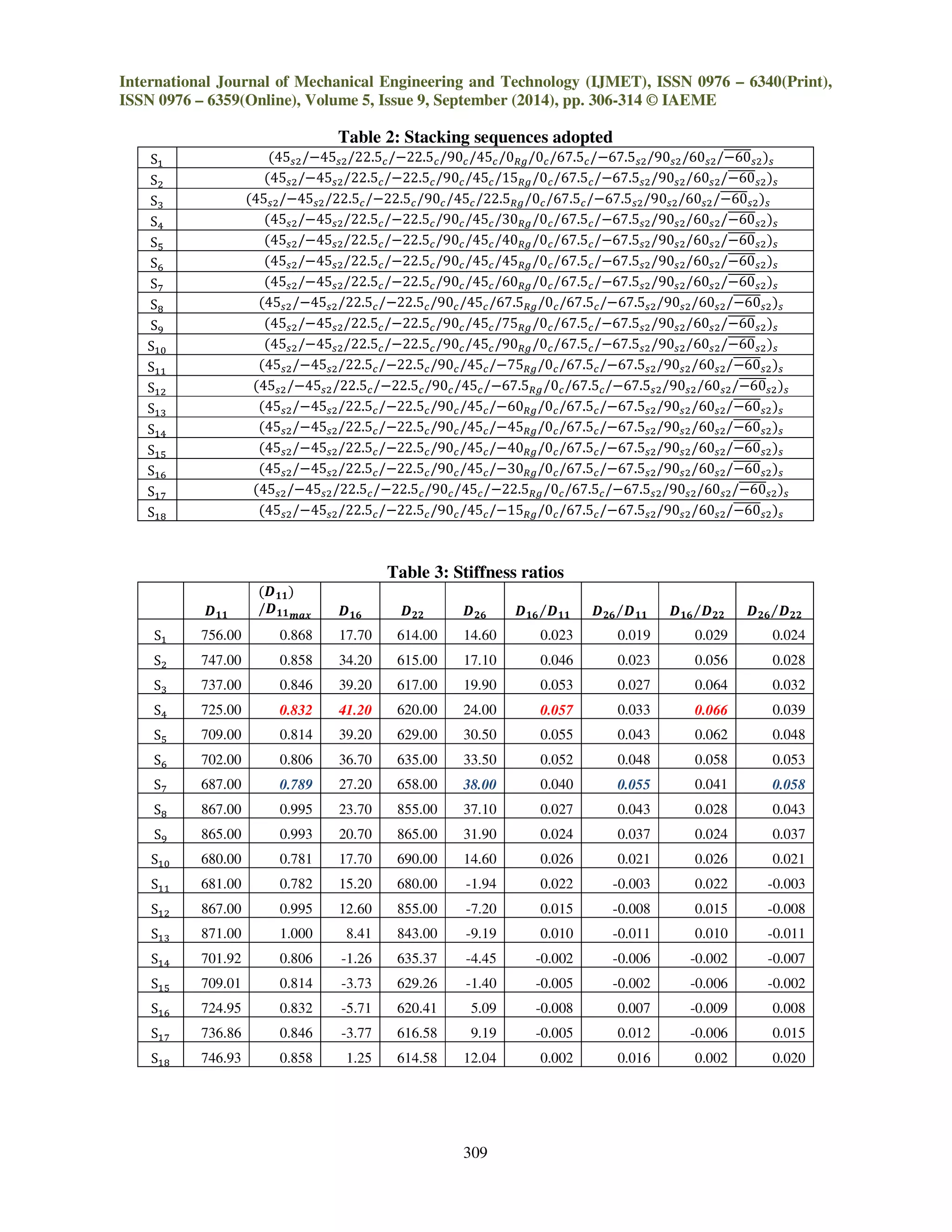
table 1. All the stacking sequences are assumed to be symmetric. As a result of selecting symmetric
laminates, extension-twist coupling is not investigated, i.e. ܤଵ and ܤଶ ൌ 0. For the purpose of
understanding the effect of bend-twist coupling on the performance of composite marine propeller,
the ply angle of the layer made of R-glass roving UD/epoxy is changed systematically in stacking
sequences ܵଵݐ ܵଵ଼ from 90
ݐ െ 90
as shown in table 2. For better understanding the propeller
characteristics, the stiffness ratios of ܦଵ/ܦଵଵ, ܦଶ/ܦଵଵ, ܦଵ/ܦଶଶ, ܽ݊݀ ܦଶ/ܦଶଶ versus ߠ for the
laminateሺ45௦ଶ/െ45௦ଶ/22.5/െ22.5/90/45/ߠோ/0/67.5/െ67.5௦ଶ/90௦ଶ/60௦ଶ/ െ60തതതതതത௦ଶሻ௦ are
tabulated for each of the sequences as shown in table 3 and are plotted in fig 1.
Table 1: Material properties
R Glass roving UD / Epoxy S2 Glass fabric /
Epoxy
Carbon UD / Epoxy
thickness 0.3 mm 0.32mm 0.3mm
Density (gm/cc) 2 1.8 1.6
۳( Gpa) 48.3 22.92 25
۳ 12.4 22.92 10
۳ 12.4 12.4 10
ૅ 0.16 0.12 0.16
ૅ 0.28 0.2 0.2
ૅ 0.28 0.2 0.16
۵(Gpa) 6.6 4.7 5.2
۵ 4.14 4.2 3.8
۵ 4.14 4.2 6](https://image.slidesharecdn.com/bend-twist-coupling-and-its-effect-on-cavitation-inception-of-composite-marine-propeller-160218105350/75/BEND-TWIST-COUPLING-AND-ITS-EFFECT-ON-CAVITATION-INCEPTION-OF-COMPOSITE-MARINE-PROPELLER-3-2048.jpg)
![International Journal of Mechanical Engineering and Technology (IJMET), ISSN 0976 – 6340(Print),
ISSN 0976 – 6359(Online), Volume 5, Issue 9, September (2014), pp. 306-314 © IAEME
310
As ߠ is varied from 0
in either the positive or negative direction, ܦଵ/ܦଵଵ changes at higher
rate compared to ܦଶ/ܦଵଵ, and is maximum at plus or minus 30
. The ratio ܦଶ/ܦଵଵ changes at a
lower rate, peaking at േ60
. As expected ܦଶଶ/ܦଵଵ is minimum for 0
andേ90
. As reported in [8],
higher values of these ratios lead to the more twisting effect about the ࢞ and ࢟ axis thereby
producing more coupling effect. The propeller with the high values of ܦଵ ܦଵଵ⁄ , ܦଵ ܦଶଶ⁄ and
ܦଶ ܦଵଵ⁄ and ܦଶ ܦଶଶ⁄ , can attain the higher values of blade setting angles . Accordingly, stacking
sequences ܵସ and ܵ are chosen, which has got higher values ofܦଵ ܦଵଵ⁄ ,ܦଵ ܦଶଶ⁄ , ܦଶ ܦଵଵ⁄ and
ܦଶ ܦଶଶ⁄ , for the composite propeller. ܦଵଵ/ܦଵଵ௫
, will provide a measure of the relative bending
stiffness of the propellers. As it is maximum for sequence ܵସ , compared to sequenceܵ, sequence ܵସ
is selected for the composite propeller. The material data and layup sequence is incorporated in
hyper-mesh 9.0, having a total of 25 layers.
Fig 1: Stiffnesses of different stacking sequences
IV. FLUID-STRUCTURE INTERACTION (FSI)
The hydro-elastic model basically accounts for the fluid structure interaction (FSI), as
presented in [10]. The displacement field, {,}ݑ is determined using the finite element method in
structural model realized with ANSYS, and the hydrodynamic pressure field, {,} is determined
using the finite volume method in the hydrodynamic model realized through FLUENT. The
equilibrium between the hydrodynamic and structural forces is obtained by the hydro-elastic model.
That is, the hydro-elastic model determines the displacement vector {}ݑ which satisfies the
ሾܭሿሼݑሽ ൌ ሼሽ (2)
Where, [K] is the structural stiffness matrix which can be tailored by laminate lay-up
sequence. The displacement field is determined by the structural model for the given pressure
-90 -70 -50 -30 -10 10 30 50 70 90
-0.02
-0.01
0
0.01
0.02
0.03
0.04
0.05
0.06
0.07
0.8
0.85
0.9
0.95
1
D16/D11,D26/D11,D16,D22andD26/D22
D22/D11
θ in Degrees
Stiffnesses of different stacking sequences
(D22/D11) D16/D11 D26/D11 D16/D22 D26/D22](https://image.slidesharecdn.com/bend-twist-coupling-and-its-effect-on-cavitation-inception-of-composite-marine-propeller-160218105350/75/BEND-TWIST-COUPLING-AND-ITS-EFFECT-ON-CAVITATION-INCEPTION-OF-COMPOSITE-MARINE-PROPELLER-5-2048.jpg)
![International Journal of Mechanical Engineering and Technology (IJMET), ISSN 0976 – 6340(Print),
ISSN 0976 – 6359(Online), Volume 5, Issue 9, September (2014), pp. 306-314 © IAEME
313
VI. CONCLUSIONS
Following conclusions are drawn from the above work.
1. The numerical method adopted in the research work successfully predicted the open water
characteristics of a marine propeller, validated through experiments.
2. Fluid structure interactions are accounted using the hydro-elastic model used for composite
propellers.
3. Bend-twist coupling in composites is explored systematically for the better performance of a
composite propeller compared to metallic propeller.
4. The effect of bend-twist coupling on the cavitation performance of a marine propeller is
studied systematically by varying the fiber orientation of the R glass roving/epoxy lamina.
5. The operating range of the metallic propeller over which, it can perform without cavitation
from design condition is between the advance coefficients 0.943-0.54. The maximum open
water efficiency in the given range is 71%.
6. The operating range for the composite propeller over which, it can perform without cavitation
is between the advance coefficients 0.934-0.45. The maximum open water efficiency in the
given range is 69.9%.
7. Without sacrificing the efficiency of a propeller, the range of advance coefficients over which
the composite propeller do not cavitate is increased by 22% compared to metallic propeller.
ACKNOWLEDGEMENTS
The Authors would like to thank the NSTL, Vizag for permitting to conduct the cavitation
tunnel tests.
REFERENCES
Journal Papers
[1] Ya-Jung Lee, Ching-Chieh Lin, Optimized design of composite propeller, Mechanics of
advanced materials and structures, 11:17-30,2004.
[2] Arakeri V.H and Accosta AJ, 1973 “Viscous effects in the inception of cavitation on
axisymmetric bodies”.
[3] Arakeri, V. H., 1975, “Viscous Effects on the Position of Cavitation Separation from
Smooth Bodies,” J. Fluid Mech., 68, pp. 779–799.
[4] Arakeri, V. H., Carroll, J. A., and Holl, J. W., 1981, “A Note on the Effect of Short and Long
Laminar Separation Bubbles on Desinent Cavitation,” ASME J. Fluids Eng., 1031,
pp. 28–32.
[5] Van der Meulen, J. H. J., 1978, “A Holographic Study of the Influence of Boundary Layer
and Surface Characteristics on Inception and Developed Cavitation on Axisymmetric
Bodies,” Proceedings of 12th Symposium on Na- val Hydrodynamics, Washington, DC,
pp. 443–451.
[6] Van der Meulen, J. H. J., 1980, “Boundary Layer and Cavitation Studies of NACA 16–012
and NACA 4412 Hydrofoils,” Proceedings of 13th Symposium on Naval Hydrodynamics,
Tokyo, Japan, pp. 195–219.
[7] Ching-Chieh Lin, Ya-Jung Lee, Chu-Sung Hung, Optimization and experiment of composite
marine propellers, Composite structures, 2008.](https://image.slidesharecdn.com/bend-twist-coupling-and-its-effect-on-cavitation-inception-of-composite-marine-propeller-160218105350/75/BEND-TWIST-COUPLING-AND-ITS-EFFECT-ON-CAVITATION-INCEPTION-OF-COMPOSITE-MARINE-PROPELLER-8-2048.jpg)
![International Journal of Mechanical Engineering and Technology (IJMET), ISSN 0976 – 6340(Print),
ISSN 0976 – 6359(Online), Volume 5, Issue 9, September (2014), pp. 306-314 © IAEME
314
[8] Abdul M.Khan, Daniel O.Adams, Effects of bend-twist coupling on composite propeller
performance, Mechanics of Composite materials and structures, 7: 383-401, 2000.
[9] S.Solomon Raj, and P.Ravinder reddy., “ Performance evaluation of composite marine
propeller using L8 orthogonal array,” International Journal of engineering science and
technology, Vol.3,No.11, November 2011.
[10] José Pedro Blasques,
, Christian Berggreen, Poul Andersen, Hydro-elastic analysis and
optimization of a composite marine propeller, Marine Structures Volume 23, Issue 1,
January 2010, Pages 22–38.
Books
[11] R.M.Jones, Mechanics of composites materials, second edition, Taylor&Francis.
[12] Ever J.Barbero, Introduction to composite material design, Taylor& Francis.
[13] Ronald F.Gibson, Principles of composite material mechanics, second edition, CRC press.
[14] Ever J.Barbero, Finite element analysis of composite materials, Taylor& Francis.](https://image.slidesharecdn.com/bend-twist-coupling-and-its-effect-on-cavitation-inception-of-composite-marine-propeller-160218105350/75/BEND-TWIST-COUPLING-AND-ITS-EFFECT-ON-CAVITATION-INCEPTION-OF-COMPOSITE-MARINE-PROPELLER-9-2048.jpg)

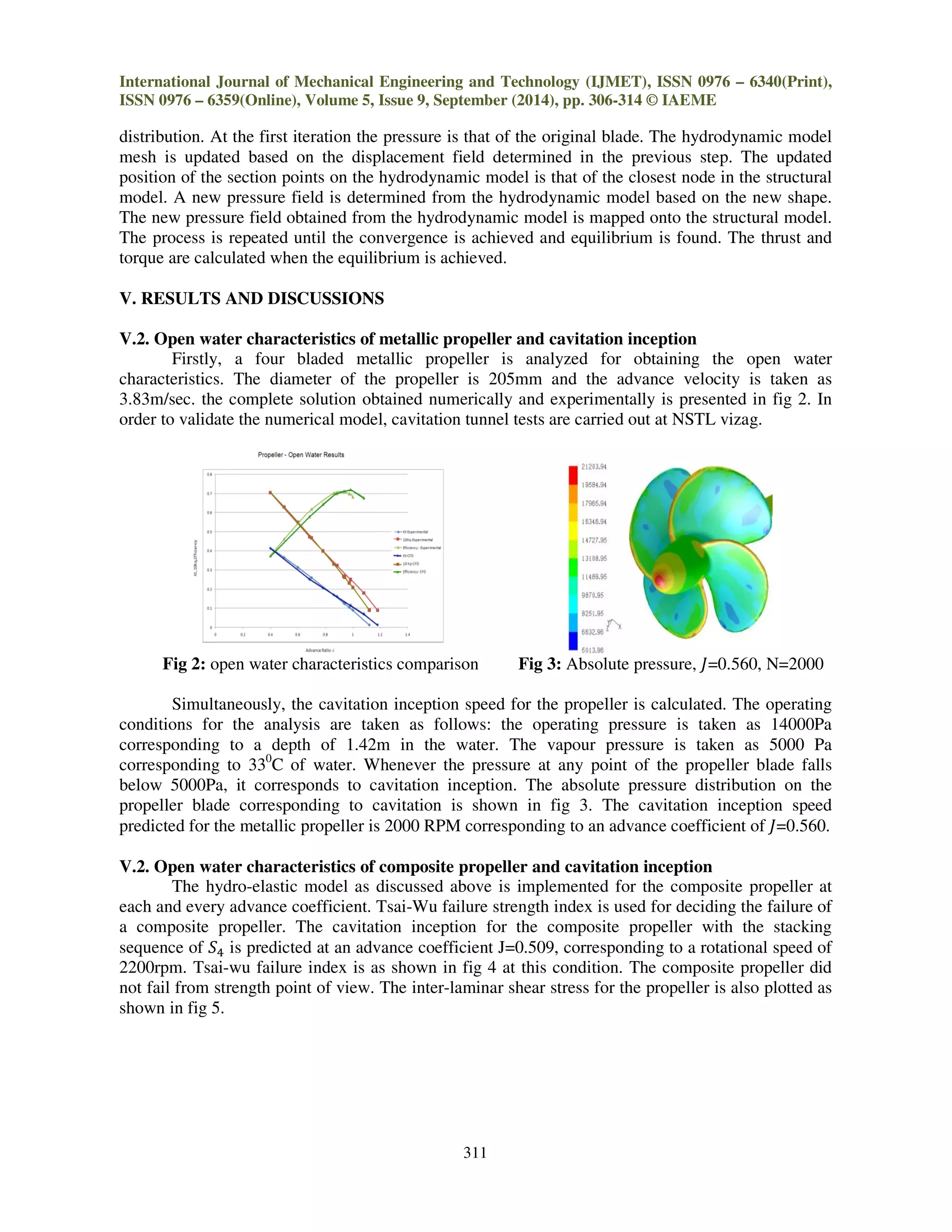
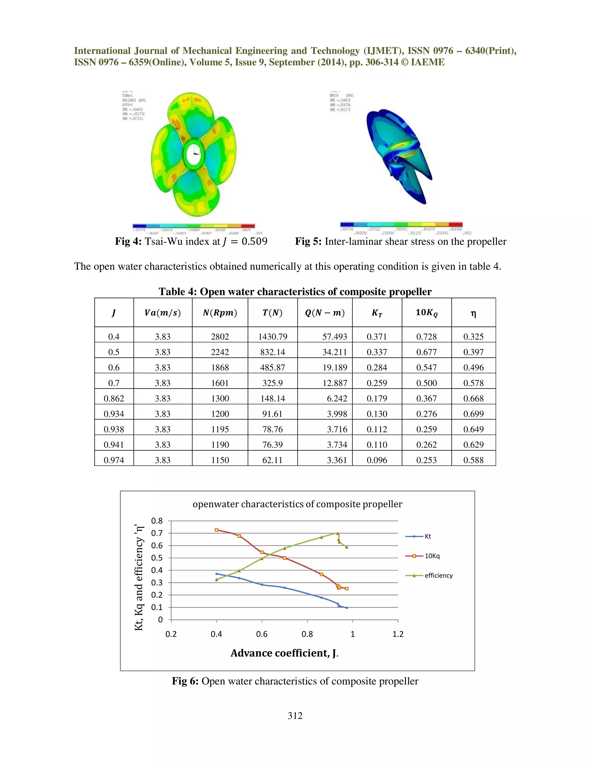
The document discusses the design and performance enhancement of composite marine propellers by utilizing bend-twist coupling, which helps mitigate cavitation effects associated with traditional metallic propellers. Through fluid structure interaction simulations and experimental validations in cavitation tunnels, it is shown that composite propellers can offer improved operating ranges and reduce noise and vibration resulting from cavitation. The research emphasizes the importance of stacking sequences in composite materials to achieve better performance compared to conventional propellers made from nickel-aluminum-bronze.


