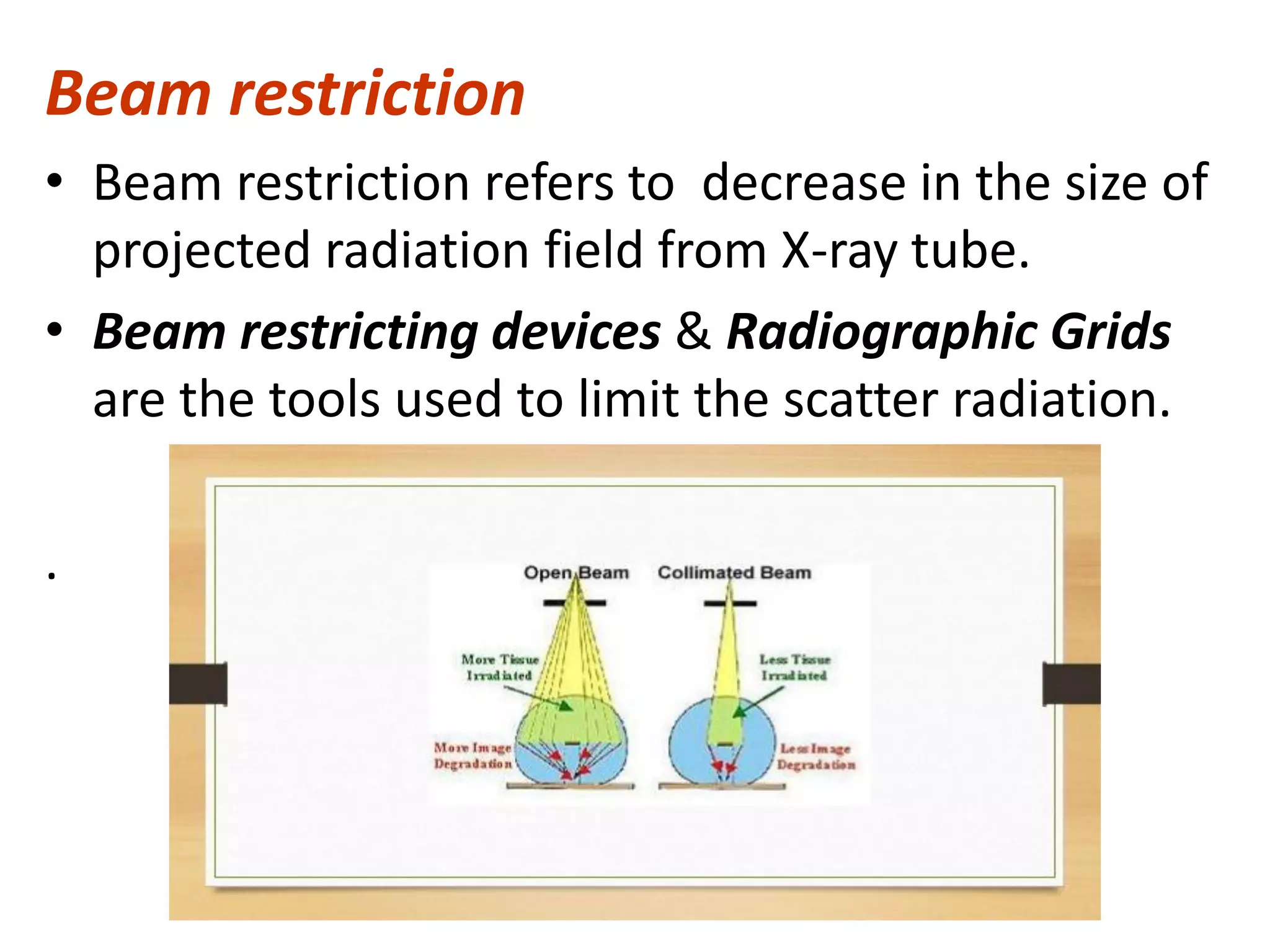
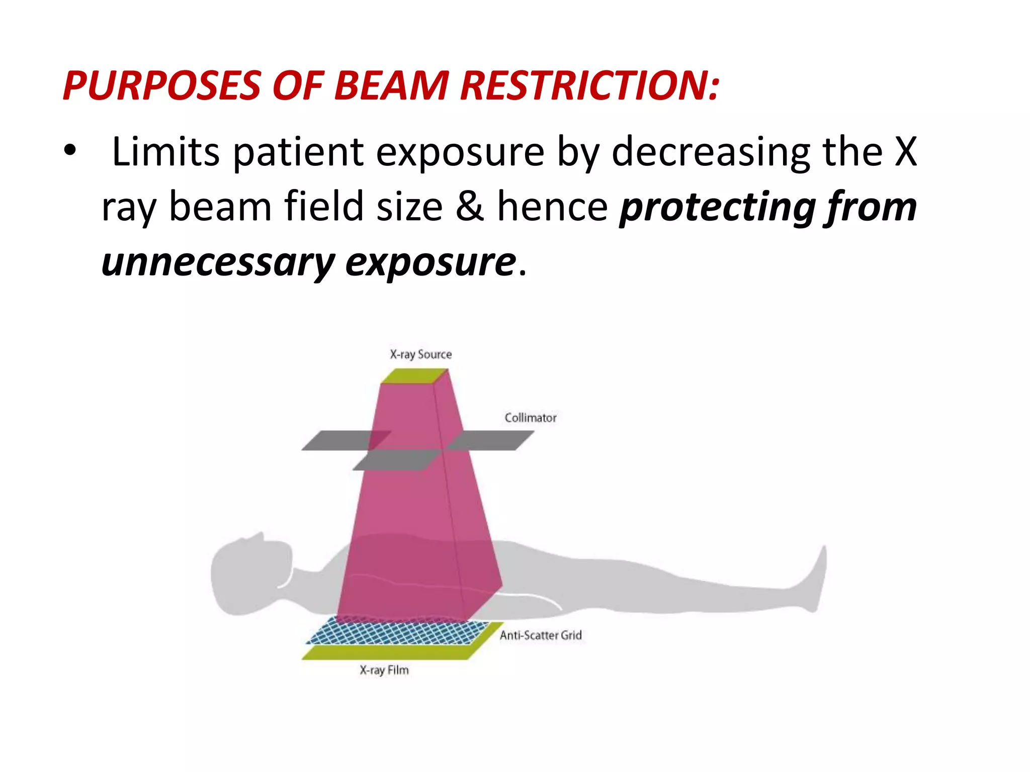
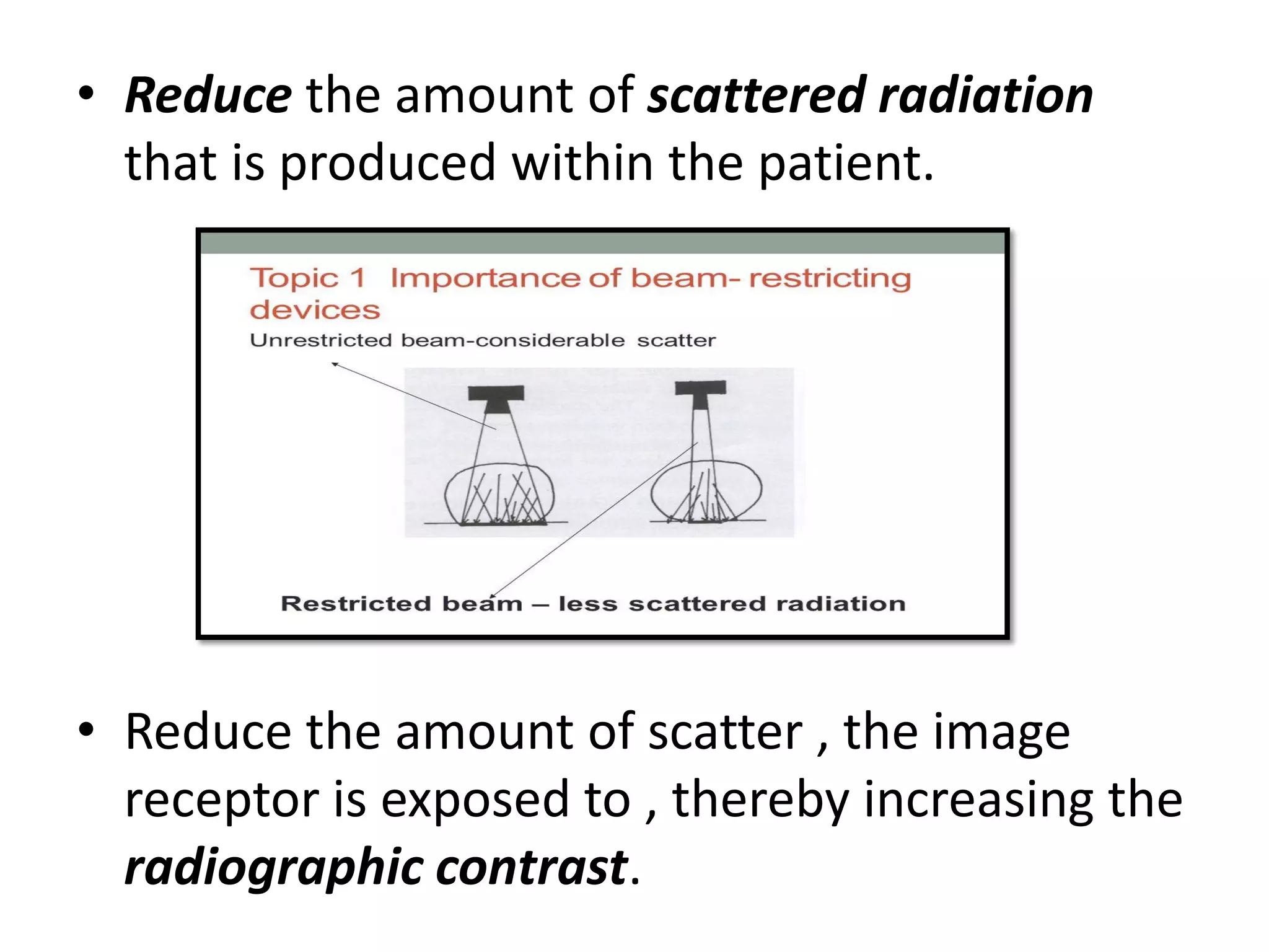
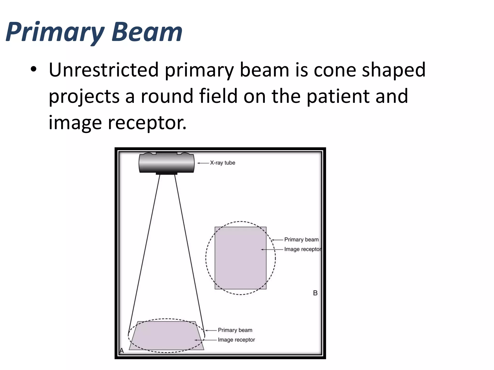
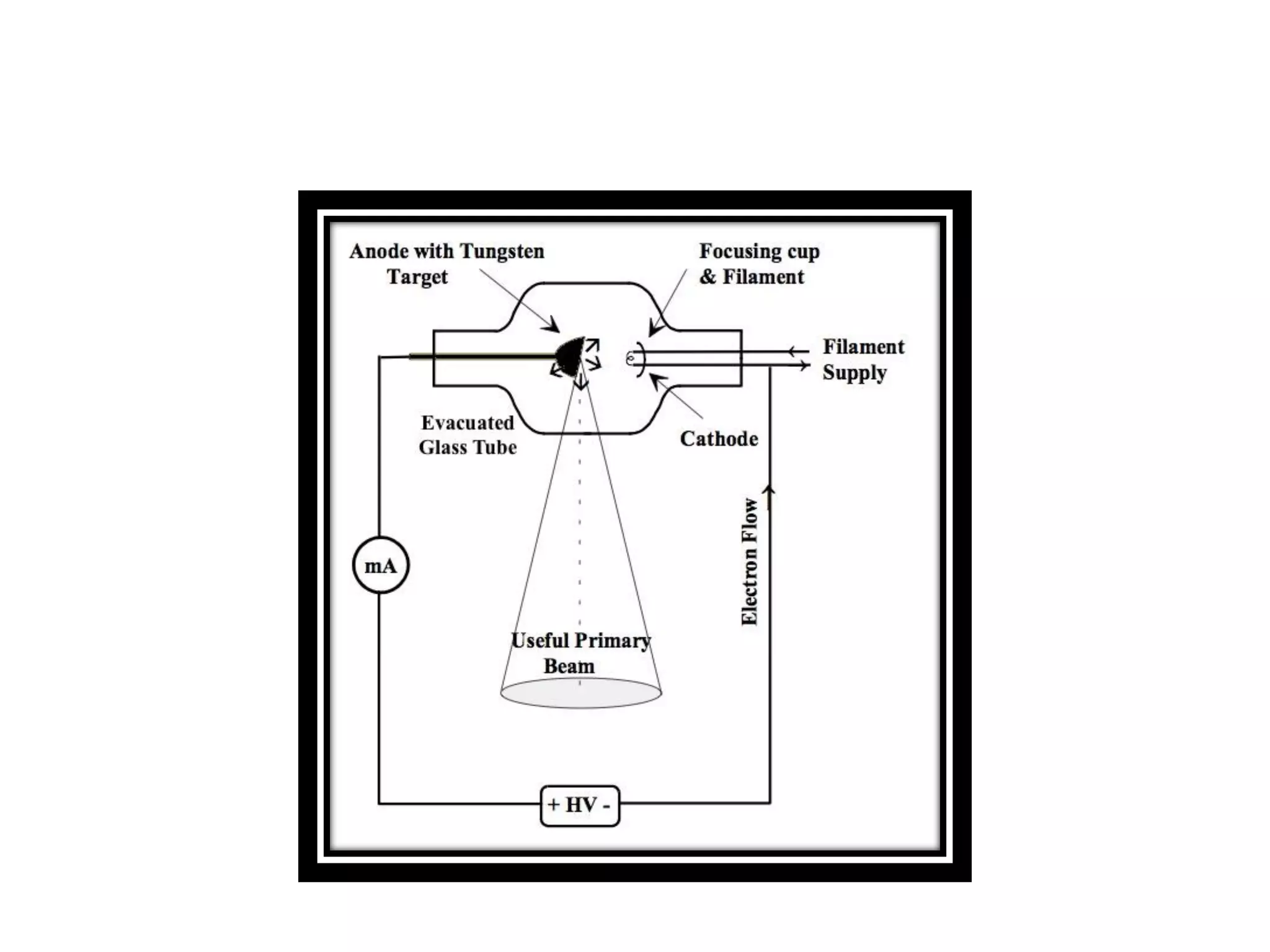
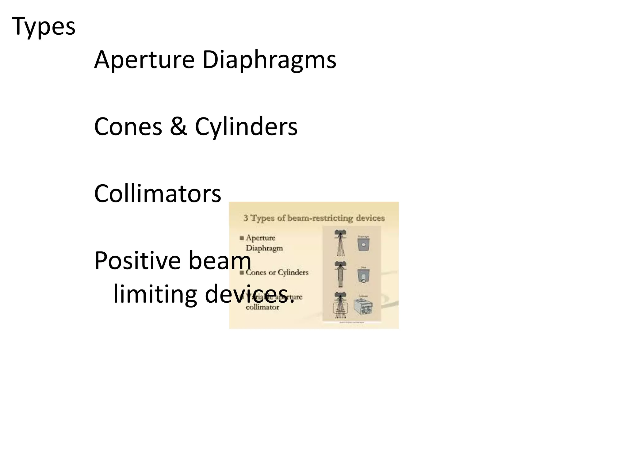
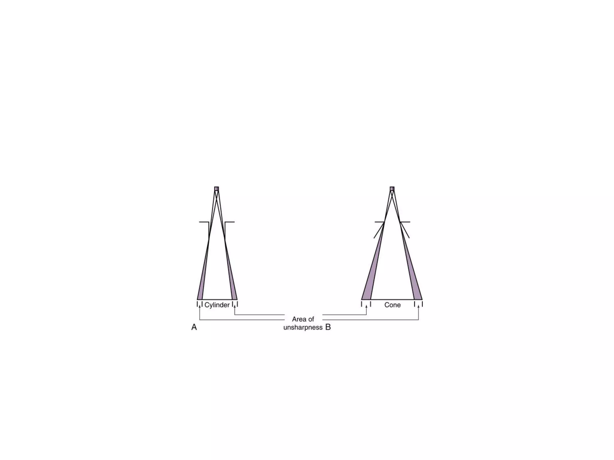
BEAM RESTRICTION
MUHAMMED ASLAM BS
BSC MIT
Beam restriction
• Beam restriction refers to decrease in the size of
projected radiation field from X-ray tube.
• Beam restricting devices & Radiographic Grids
are the tools used to limit the scatter radiation.
.
PURPOSES OF BEAM RESTRICTION:
• Limits patient exposure by decreasing the X
ray beam field size & hence protecting from
unnecessary exposure.
• Reduce the amount of scattered radiation
that is produced within the patient.
• Reduce the amount of scatter , the image
receptor is exposed to , thereby increasing the
radiographic contrast.
Primary Beam
• Unrestricted primary beam is cone shaped
projects a round field on the patient and
image receptor.
• If left unrestricted , it results in unnecessary
patient exposure.
• Limiting the field size of beam is achieved with
beam restricting device.
• They are placed just below the x-ray tube
housing to change the size & shape of primary
beam.
• Collimators are the most popular beam
restricting devices.
• Increasing the collimation implies decreasing
the field size & hence radiation dose to
patient.
• Decreasing the collimation means increasing
the field size.
Beam restriction & Scattered radiation
• Beam restricting devices reduce scattered
radiation
• This reduce amount of scatter the image
receptor is exposed
• Thus increasing the radiographic contrast
Collimation & Radiographic density
• Due to reduction in scattered radiation
produced , Collimation affects the number of
photons reaching the image receptor.
• This decreases the radiographic density
produced.
• Therefore exposure factors may be needed to
be increased when collimation is increased to
compensate for the loss of density.
• kVp value shouldn't be increased as it results
in decreased contrast
• To change only density of radiographic image ,
mAs should be changed.
• A significant collimation requires an increase
in as much as 30-50% of the mAs to
compensate for loss in density that occurs
because of collimation.
Beam restricting devices
• Made up of metal or a combination of metals
that readily absorb X-rays.
• They differ in sophistication & utility.
Types
Aperture Diaphragms
Cones & Cylinders
Collimators
Positive beam
limiting devices.
Aperture Diaphragms
• It is flat piece of lead diaphragm that has a
hole in it .
• They are placed directly below the X ray tube
window .
• They can be made by cutting the rubberized
Lead into size needed to create the diaphragm
& cutting the center to create the shape & size
of aperture
ADVANTAGES
• Simplest type of BRD
• Easy to use.
• The aperture’s size & shape can be changed.
• Home made or commercially made apertures
are available for the purpose of radiographic
unit.
DISADVANTAGES
• The aperture cannot be adjusted from the
designed size.
• Therefore the projected field size is not
adjustable.
• Because of aperture’s proximity to the
radiation source , a large area of unsharpness
surrounds the radiographic image called as
Penumbra.
Cones & Cylinders
• A Cone or Cylinder is essentially an aperture
diaphragm that has an extended flange
attached to it.
• The flange can very in length & can be shaped
as either a cone or cylinder.
• Though shaped differently , they have many of
the same attributes.
• The flange can also be made to telescope ,
thereby increasing its total length.
ADVANTAGES
• Easy to use
• They slide onto the tube , directly below the
window
• They limit unsharpness surrounding the
radiographic image more than the aperture
diaphragms , with Cylinders accomplishing the
task slightly better than Cones.
• Cones & Cylinders are almost made to
produce a circular field.
• Therefore they can be used to advantage for
particular radiographic procedures like
radiography of sinuses , mastoid & gallbladder.
DISADVANTAGES
• They are limited in terms of the sizes they are
available.
• They are not necessarily interchangeable among
tube housings.
• If the angle of the flange of cone is greater than
the angle of divergence of primary beam , the
base plate is the only metal actually restricting
the primary beam.
• Therefore Cylinders are generally more useful
than Cones.
COLLIMATORS
• A collimator has 2 or 3 sets of lead shutters.
• Located immediately below the tube window.
• Beam restriction achieved by the use of a
collimator is called Collimation.
Parts of a Collimator
• Sets of lead shutters
• Light source & mirror
• Plastic template with cross hair/lines on it.
• These shutters consists of longitudinal & lateral
leaves , each with its own control.
• The entrance shutters limit the X ray beam much
as the aperture diaphragm would.
• 1st set acts as an aperture & 2nd set acts to
deletes the penumbra produced by 1st.
• This makes the collimator adjustable in terms of
its ability to produce projected fields of varying
sizes
• Field shaped produced is always rectangular
or square unless a diaphragm or cone is slid in
below the collimator.
• They are equipped with a light source & a
mirror to project a light field onto the patient.
• The light is intended to accurately indicate
where the primary X-ray beam will be
projected during the exposure.
• A plastic template with cross hairs is affixed to
the bottom of collimator to indicate where the
center of the primary beam i.e. the central ray
will be directed.
• It helps in accurately centering the X ray field
to the patient as
the field is being
illuminted.
Drawbacks
• The mirror that reflects the light down
towards the patient or the light bulb itself
could be slightly out of position
• This can result in lack of accuracy of the light
bulb field.
• In such case the projected light field
inaccurately indicate where primary beam will
be projected.
• Present on the front of the collimator.
• In case of failure of light , it indicates the
projected field size based on the adjusted size
of collimator opening at a particular source to
image distance.
X Ray field measurement guide
Quality Control Check
- Collimator & Beam alignment test.
• Means of testing the accuracy of light field &
location of center of projected beam.
• Lack of congruency of X ray field & exposure field
, and misalignment of the light & Bucky tray ,
affect the quality of radiography.
• Collimator misalignment should be less than 2%
of source-to-image receptor distance used.
• The perpendicularity of central ray must be < or =
to 1 degree misaligned.
Automated Collimators
• Also known as Positive Beam-Limiting devices
• The device automatically limits the size &
shape of primary beam to the size & shape of
image receptor.
• The shutters are motor driven.
• The sensors in the buckey tray identify the size
& alignment of cassette and relay info to
collimators , which position the shutters to
exactly match the size of film being used.
Conclusion
• Beam restrictors are devices that regulate the
size & shape of X ray beam
• Three types- Aperture diaphragms , Cones &
Cylinders and Collimators.
• They are used to decrease the scattered
radiation and hence protection of patient
from unnecessary radiation and also a better
radiographic image quality .

Beam restriction

  • 1.
  • 2.
    Beam restriction • Beamrestriction refers to decrease in the size of projected radiation field from X-ray tube. • Beam restricting devices & Radiographic Grids are the tools used to limit the scatter radiation. .
  • 3.
    PURPOSES OF BEAMRESTRICTION: • Limits patient exposure by decreasing the X ray beam field size & hence protecting from unnecessary exposure.
  • 4.
    • Reduce theamount of scattered radiation that is produced within the patient. • Reduce the amount of scatter , the image receptor is exposed to , thereby increasing the radiographic contrast.
  • 5.
    Primary Beam • Unrestrictedprimary beam is cone shaped projects a round field on the patient and image receptor.
  • 7.
    • If leftunrestricted , it results in unnecessary patient exposure. • Limiting the field size of beam is achieved with beam restricting device. • They are placed just below the x-ray tube housing to change the size & shape of primary beam.
  • 8.
    • Collimators arethe most popular beam restricting devices. • Increasing the collimation implies decreasing the field size & hence radiation dose to patient. • Decreasing the collimation means increasing the field size.
  • 10.
    Beam restriction &Scattered radiation • Beam restricting devices reduce scattered radiation • This reduce amount of scatter the image receptor is exposed • Thus increasing the radiographic contrast
  • 11.
    Collimation & Radiographicdensity • Due to reduction in scattered radiation produced , Collimation affects the number of photons reaching the image receptor. • This decreases the radiographic density produced. • Therefore exposure factors may be needed to be increased when collimation is increased to compensate for the loss of density.
  • 12.
    • kVp valueshouldn't be increased as it results in decreased contrast • To change only density of radiographic image , mAs should be changed. • A significant collimation requires an increase in as much as 30-50% of the mAs to compensate for loss in density that occurs because of collimation.
  • 13.
    Beam restricting devices •Made up of metal or a combination of metals that readily absorb X-rays. • They differ in sophistication & utility.
  • 14.
    Types Aperture Diaphragms Cones &Cylinders Collimators Positive beam limiting devices.
  • 15.
    Aperture Diaphragms • Itis flat piece of lead diaphragm that has a hole in it . • They are placed directly below the X ray tube window . • They can be made by cutting the rubberized Lead into size needed to create the diaphragm & cutting the center to create the shape & size of aperture
  • 17.
    ADVANTAGES • Simplest typeof BRD • Easy to use. • The aperture’s size & shape can be changed. • Home made or commercially made apertures are available for the purpose of radiographic unit.
  • 18.
    DISADVANTAGES • The aperturecannot be adjusted from the designed size. • Therefore the projected field size is not adjustable. • Because of aperture’s proximity to the radiation source , a large area of unsharpness surrounds the radiographic image called as Penumbra.
  • 19.
    Cones & Cylinders •A Cone or Cylinder is essentially an aperture diaphragm that has an extended flange attached to it. • The flange can very in length & can be shaped as either a cone or cylinder. • Though shaped differently , they have many of the same attributes.
  • 21.
    • The flangecan also be made to telescope , thereby increasing its total length.
  • 22.
    ADVANTAGES • Easy touse • They slide onto the tube , directly below the window • They limit unsharpness surrounding the radiographic image more than the aperture diaphragms , with Cylinders accomplishing the task slightly better than Cones.
  • 24.
    • Cones &Cylinders are almost made to produce a circular field. • Therefore they can be used to advantage for particular radiographic procedures like radiography of sinuses , mastoid & gallbladder.
  • 25.
    DISADVANTAGES • They arelimited in terms of the sizes they are available. • They are not necessarily interchangeable among tube housings. • If the angle of the flange of cone is greater than the angle of divergence of primary beam , the base plate is the only metal actually restricting the primary beam. • Therefore Cylinders are generally more useful than Cones.
  • 26.
    COLLIMATORS • A collimatorhas 2 or 3 sets of lead shutters. • Located immediately below the tube window. • Beam restriction achieved by the use of a collimator is called Collimation.
  • 28.
    Parts of aCollimator • Sets of lead shutters • Light source & mirror • Plastic template with cross hair/lines on it.
  • 29.
    • These shuttersconsists of longitudinal & lateral leaves , each with its own control. • The entrance shutters limit the X ray beam much as the aperture diaphragm would. • 1st set acts as an aperture & 2nd set acts to deletes the penumbra produced by 1st. • This makes the collimator adjustable in terms of its ability to produce projected fields of varying sizes
  • 30.
    • Field shapedproduced is always rectangular or square unless a diaphragm or cone is slid in below the collimator. • They are equipped with a light source & a mirror to project a light field onto the patient. • The light is intended to accurately indicate where the primary X-ray beam will be projected during the exposure.
  • 32.
    • A plastictemplate with cross hairs is affixed to the bottom of collimator to indicate where the center of the primary beam i.e. the central ray will be directed. • It helps in accurately centering the X ray field to the patient as the field is being illuminted.
  • 33.
    Drawbacks • The mirrorthat reflects the light down towards the patient or the light bulb itself could be slightly out of position • This can result in lack of accuracy of the light bulb field. • In such case the projected light field inaccurately indicate where primary beam will be projected.
  • 34.
    • Present onthe front of the collimator. • In case of failure of light , it indicates the projected field size based on the adjusted size of collimator opening at a particular source to image distance. X Ray field measurement guide
  • 35.
    Quality Control Check -Collimator & Beam alignment test. • Means of testing the accuracy of light field & location of center of projected beam. • Lack of congruency of X ray field & exposure field , and misalignment of the light & Bucky tray , affect the quality of radiography. • Collimator misalignment should be less than 2% of source-to-image receptor distance used. • The perpendicularity of central ray must be < or = to 1 degree misaligned.
  • 36.
    Automated Collimators • Alsoknown as Positive Beam-Limiting devices • The device automatically limits the size & shape of primary beam to the size & shape of image receptor. • The shutters are motor driven.
  • 37.
    • The sensorsin the buckey tray identify the size & alignment of cassette and relay info to collimators , which position the shutters to exactly match the size of film being used.
  • 38.
    Conclusion • Beam restrictorsare devices that regulate the size & shape of X ray beam • Three types- Aperture diaphragms , Cones & Cylinders and Collimators. • They are used to decrease the scattered radiation and hence protection of patient from unnecessary radiation and also a better radiographic image quality .