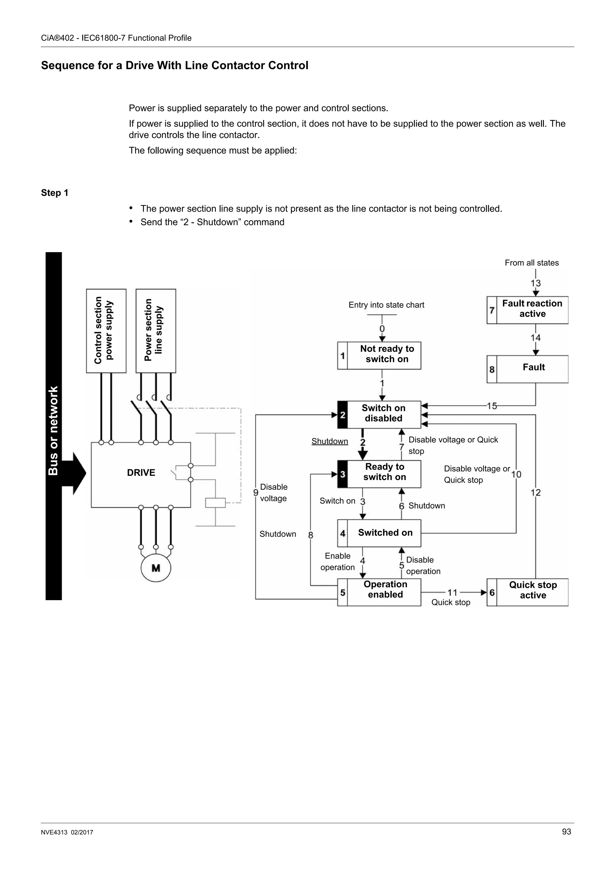
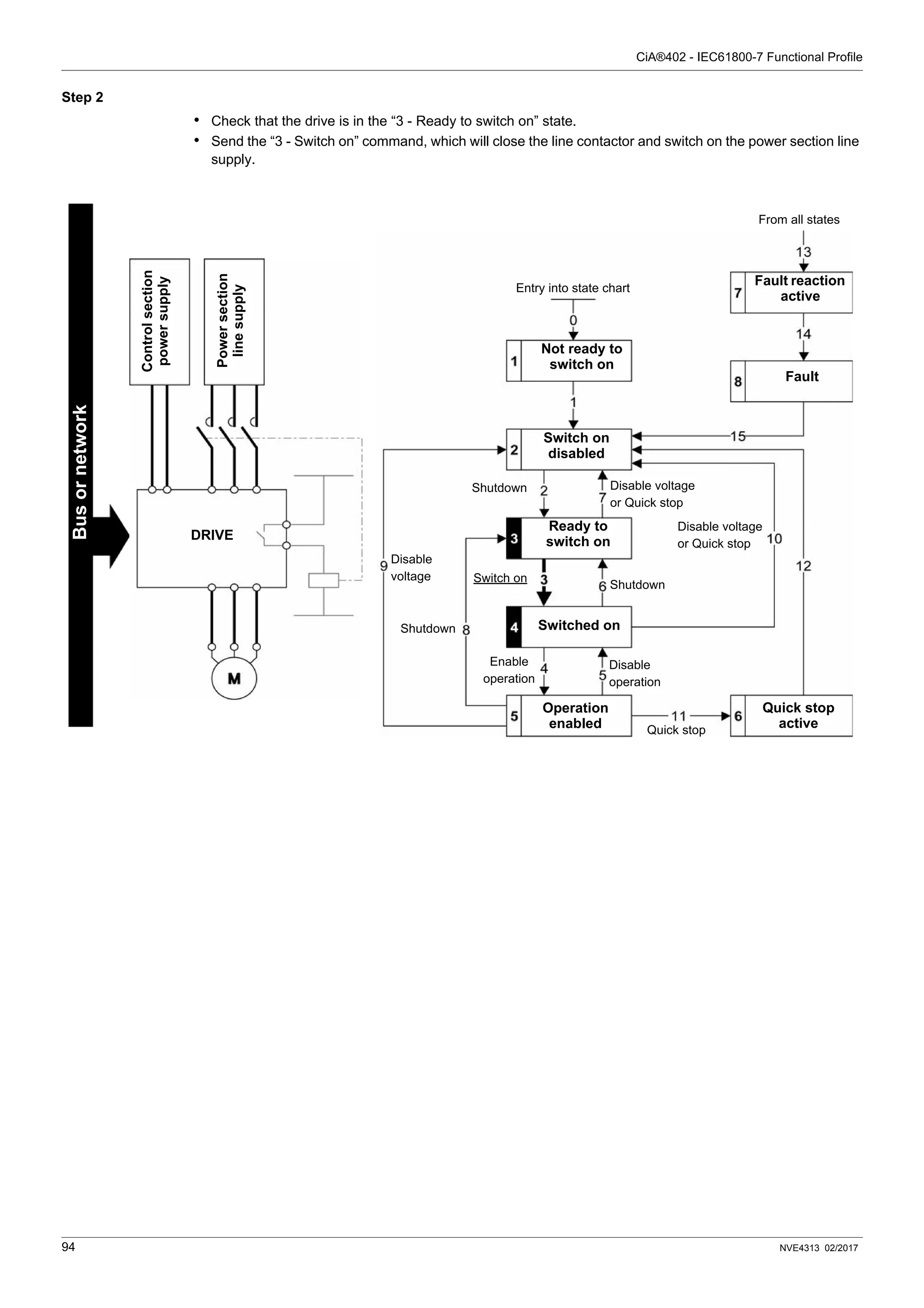
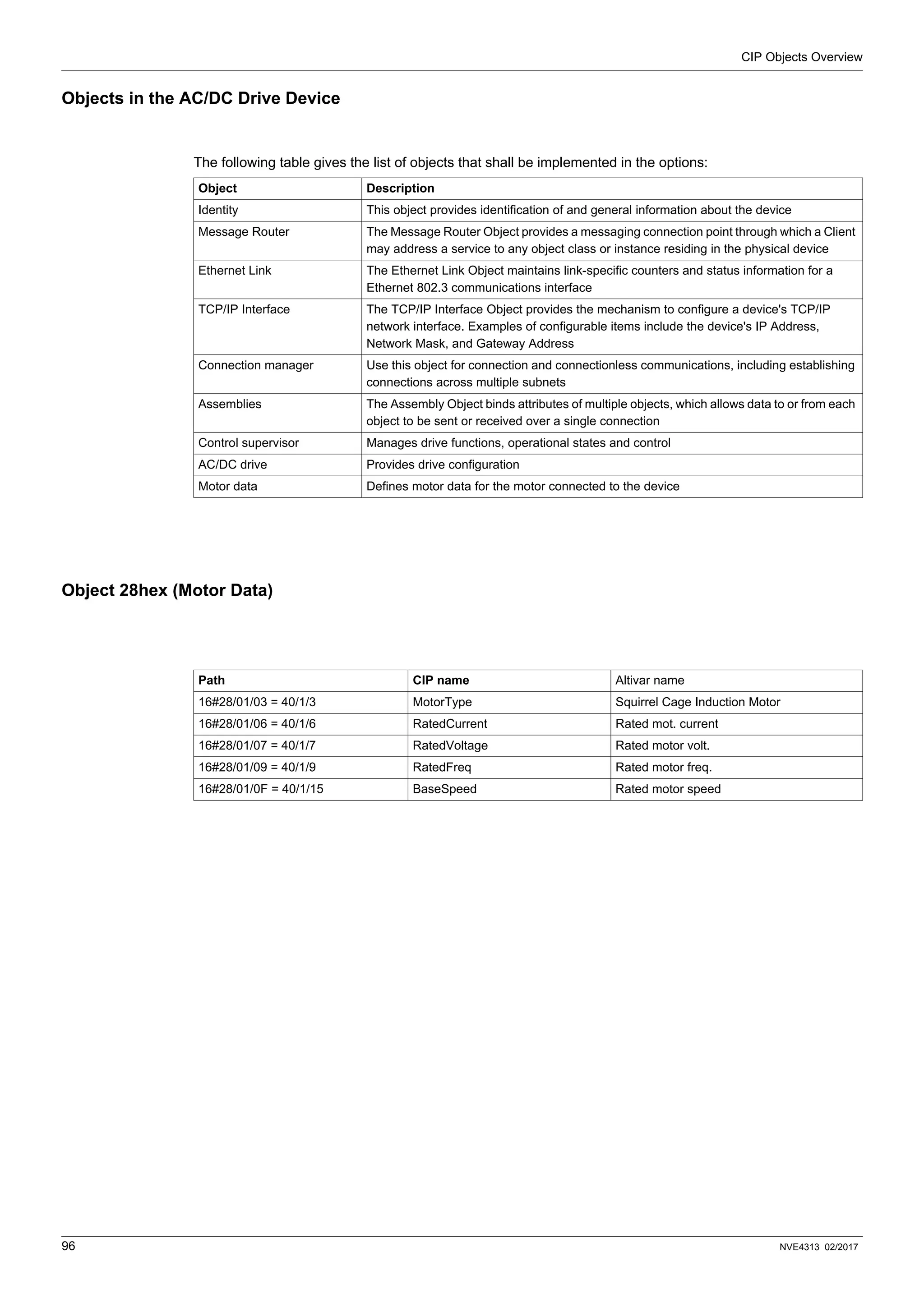
The document provides a manual for the Altivar Machine ATV320 variable speed drives, detailing installation, configuration, and operation guidelines while emphasizing safety and risk assessments for specific applications. It outlines communication protocols such as Modbus TCP and Ethernet/IP, along with hardware and software compatibility information. Schneider Electric disclaims liability for misuse and mandates adherence to safety regulations during installation and operation.


![Presentation
16 NVE4313 02/2017
Notation
Drive Terminal Displays
The graphic display terminal (to be ordered separately - reference VW3A1101) menus are shown in square
brackets.
Example: [Communication]
The integrated 7-segment display terminal menus are shown in round brackets.
Example: (COM-)
Parameter names are displayed on the graphic display terminal in square brackets.
Example: [Fallback speed]
Parameter codes are displayed on the integrated 7-segment display terminal in round brackets.
Example: (LFF)
Formats
In this manual, hexadecimal values are written as follows: 16#
Binary values are written as follows: 2#
Abbreviations
Req. = Required
Opt. = Optional](https://image.slidesharecdn.com/atv320modbustcpethernetipmanualnve4131302-240821021710-4e33f5e9/75/ATV320_Modbus_TCP_EtherNet_IP_Manual_NVE41313_02-pdf-16-2048.jpg)

![Configuration and Parameters
NVE4313 02/2017 25
Network Settings
The parameters are accessible via [Configuration] (COnF-), [Full] (FULL-), [Communication]
(COM-) menu and [Communication module] (Cbd-) submenu.
NOTE: Before entry begins, the IP address displayed is the active IP address.
Assigning IP Addresses
The drive needs 3 IP addresses:
• The drive IP address.
• The subnet mask.
• The gateway IP address.
These IP addresses can be entered directly: Using the integrated display terminal. Using the graphic display
terminal. Or using the SoMove software. They can be provided by:
• A BOOTP server (correspondence between the MAC address and the IP addresses).
• Or a DHCP server (correspondence between Device Name [Device Name] and the IP addresses).
If an IP address other than 0.0.0.0 has been entered using the display terminal or the SoMove software,
assignment using a server is disabled.
Parameter Description
(HMI mnemonic)
Range or Listed Values Default Long Name Short
Name
Access Parameter
Number
[Ethernet protocol] (EthM)
This parameter defines which protocol is
used for implicit exchanges
0:Modbus TCP
1:EtherNet/IP
0 [Modbus TCP]
[Ethernet IP]
(MtCP)
(EIP)
R/W 64241
[Rate setting] (rdS)
Rate and data settings
0: Autodetect
1: 10 Mbps Full
2: 10 Mbps Half
3: 100 Mbps Full
4: 100 Mbps Half
Auto [Auto]
[10M. full]
[10M. half]
[100M. full]
[100M. half]
(AUtO)
(10F)
(10H)
(100F)
(100H)
R/W 64251
[IP mode] (IpM)
Use this parameter to select the IP
address assignment method
0: Man
1: BOOTP
2: DHCP
DHCP [Fixed]
[BOOTP]
[DHCP]
(MAnU)
(bOOt)
(dHCP)
R/W 64250
[IP module] (IPC)
(IPC1) (IPC2) (IPC3) (IPC4)
These fields are editable when IP mode
is set to Fixed address
0 to 255 for each 4 fields - [139.160.069.241] (139)
(160)
(069)
(241)
R/W 64212
64213
64214
64215
[IP Mask] (IPM)
(IPM1) (IPM2) (IPM3) (IPM4)
These fields are editable when IP mode
is set to Fixed address
0 to 255 for each 4 fields - [255.255.254.0] (255)
(255)
(254)
(0)
R/W 64216
64217
64218
64219
[IP Gate] (IPG)
(IPG1) (IPG2) (IPG3) (IPG4)
These fields are editable when IP mode
is set to Fixed address
0 to 255 for each 4 fields - [0.0.0.0] (0)
(0)
(0)
(0)
R/W 64220
64221
64222
64223
[MAC @] (MAC)
MAC address display
[00-80-F4-XX-XX-XX] - [00-80-F4-XX-XX-XX] 0080
F4---
XX
XXXX
R 64267
64268
64269](https://image.slidesharecdn.com/atv320modbustcpethernetipmanualnve4131302-240821021710-4e33f5e9/75/ATV320_Modbus_TCP_EtherNet_IP_Manual_NVE41313_02-pdf-25-2048.jpg)
![Configuration and Parameters
26 NVE4313 02/2017
Entering IP Addresses in the Terminal
In the [Communication] (COM-) menu, [Communication module] (CBD-) submenu, enter the following
IP addresses:
• [IP card] (IPC1) (IPC2) (IPC3) (IPC4),
• [IP Mask] (IPM1) (IPM2) (IPM3) (IPM4),
• [IP Gate] (IPG1) (IPG2) (IPG3) (IPG4).
Turn the drive off and then back on again (control voltage if a separate power supply is being used), otherwise
the IP addresses are not taken into account.
If this address is modified, the new IP address entered is displayed. This IP address will be effective the next
time the drive is turned on.
Configuring BOOTP
The BOOTP service is used to assign IP addresses from the MAC address. The MAC address consisting of 6
hexadecimal digits (00-80-F4-80-xx-yy) must be entered in the BOOTP server. The MAC address appears on
the label attached to the Ethernet card.
In the [Communication] (COM-) menu, [Communication module] (CBD-) submenu:
• Leave the IP address [IP card] (IPC1) (IPC2) (IPC3) (IPC4) at the value
[0.0.0.0] (0) (0) (0) (0).
• Do not enable the FDR service: [FDR Activation] (FdrU) = [No] (nO).](https://image.slidesharecdn.com/atv320modbustcpethernetipmanualnve4131302-240821021710-4e33f5e9/75/ATV320_Modbus_TCP_EtherNet_IP_Manual_NVE41313_02-pdf-26-2048.jpg)
![Configuration and Parameters
NVE4313 02/2017 27
Modbus TCP Settings
The parameters are accessible via [Configuration] (COnF-), [Full] (FULL-), [Communication]
(COM-) menu and [Communication module] (Cbd-) submenu.
These settings are only visible when the parameter [Ethernet protocol] (EtHM) is defined on
[ModbusTCP] (MbtP):
Parameter Description
(HMI mnemonic)
Range or Listed Values Default Long
Name
Short
Name
Access Parameter
Number
[MAC @] (MAC)
MAC address display
[00-80-F4-XX-XX-XX] - [00-80-F4-XX-
XX-XX]
0080
F4---
XX
XXXX
R 64267
64268
64269
[Rate setting] (rdS) 0: Autodetect
1: 10 Mbps Full
2: 10 Mbps Half
3: 100 Mbps Full
4: 100 Mbps Half
Auto [Auto]
[10M. full]
[10M. half]
[100M. full]
[100M. half]
(AUtO)
(10F)
(10H)
(100F)
(100H)
R/W 64251
[Ethernet protocol] (EthM) 0:Modbus TCP
1:EtherNet/IP
0 [Modbus TCP]
[EthernetIP]
(MbtP)
(EtIP)
R/W 64241
[IP mode] (IpM)
Use this parameter to select the IP
address assignment method
0: Man
1: BOOTP
2: DHCP
DHCP [Fixed]
[BOOTP]
[DHCP]
(MAnU)
(bOOt)
(dHCP)
R/W 64250
[IP Module] (IPC)
(IPC1) (IPC2) (IPC3)
(IPC4) These fields are editable
when IP mode is set to Fixed
address
0 to 255 for each 4 fields 0.0.0.0 [0.0.0.0] (0)
(0)
(0)
(0)
R/W 64212
64213
64214
64215
[IP Gate] (IPG)
(IPG1) (IPG2) (IPG3)
(IPG4)
These fields are editable when IP
mode is set to Fixed address
0 to 255 for each 4 fields - [0.0.0.0] (0)
(0)
(0)
(0)
R/W 64220
64221
64222
64223
[IP Master] (IPp)
(IPp1) (IPp2) (IPp3)
(IPp4) These fields define the
address of the device which
retains control of the drive
0 to 255 for each 4 fields 0.0.0.0 [0.0.0.0] (0)
(0)
(0)
(0)
R/W 64234
64235
64236
64237
[IP FDR] (IPF)
(IPF1) (IPF2) (IPF3)
(IPF4) These fields displays the
served address of the FDR server
0 to 255 for each 4 fields 0.0.0.0 [0.0.0.0] (0)
(0)
(0)
(0)
R/W 64224
64225
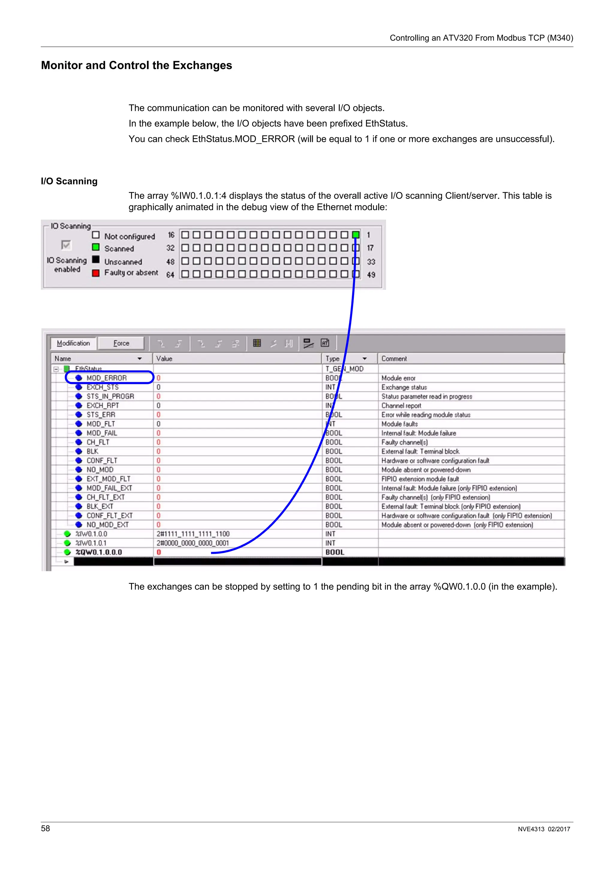
64226
64227
[FDR Activation] (FdrU)
Enable FDR service
0: no
1: yes
yes [No]
[Yes]
(nO)
(YES)
R/W 64228
[FDR Action] (FdrA) NOT ACTIVE: No command
SAVE: save command
REST: download command
DEL: delete command
IDLE [NOT ACTIVE]
[SAVE]
[REST]
[DEL]
(IdLE)
(SAUE)
(rESt)
(dEL)
R/W 64229
[FDR Autosave] (FdrS)
Interval for periodic saving of the
FDR service
0: no
1: yes
no [No]
[Yes]
(nO)
(YES)
R/W 64230
[FDR Autosave Timer] (Fdrt) 0 to 9999 minutes 0 [0] (0) R/W 64231](https://image.slidesharecdn.com/atv320modbustcpethernetipmanualnve4131302-240821021710-4e33f5e9/75/ATV320_Modbus_TCP_EtherNet_IP_Manual_NVE41313_02-pdf-27-2048.jpg)
![Configuration and Parameters
28 NVE4313 02/2017
[FDR Status] (FdrE)
FDR service status
- NOT ACTIVE: idle state
- INIT: initialisation
- CONF: configuration
- RDY: ready
- GET: download the current
configuration
- SET: save the current configuration
- APP: Write the FDR server conf. to the
drive
- OPE: operational
- UCFG: not configured
IDLE [NOT ACTIVE]
[INIT]
[CONF]
[RDY]
[GET]
[SET]
[APP]
[OPE]
[UCFG]
(IdLE)
(INIt)
(CONF)
(rdY)
(GEt)
(SEt)
(APP)
(OPE)
(UCFG)
RW 64232
[FDR file error] (FdrF)
Enable FDR detected fault
management
0: no
1: yes
yes [No]
[Yes]
(nO)
(YES)
R/W 64240
[Ethernet local conf] (LCFG)
Selection of local or server
configuration
0: no
1: yes
no [No]
[Yes]
(nO)
(YES)
R/W 64238
[Eth IO scan act] (IOSA)
Enable I/O scanner
0: no
1: Yes
- [No]
[Yes]
(nO)
(YES)
R/W 64239
[Services] (EWE-)
Enable web services
0: No web services
1: Web server enabled
1 - - R/W -
[Ethernet Timeout] (tOUt) 0.5 to 60 s
0: disabled
2.0 [2.0s] (2.0) R/W 64211
[FDR Error Code] (Fdrd) - 0: No error
- 2: the FDR configuration file is not
compatible with the drive type
- 3: Detected error reading the FDR
configuration file on the server
- 4: Detected error writing the
configuration file to the server
- 7:Time out for receipt of the FDR
configuration file from the server
- 9: duplicated IP address.
- 12:the FDR configuration file is
missing
- 13: the FDR configuration file
deployment on the drive has detected
an error (local detected error)
- 14: the configuration file delete
request has detected an error on the
FDR server
0 [0]
[2]
[3]
[4]
[7]
[9]
[12]
[13]
[14]
(0)
(2)
(3)
(4)
(7)
(9)
(12)
(13)
(14)
R 64233
[Scan.Out1 address] (OCA1) Eligible modbus address CM [OCA1] (OCA1) R/W 15421
[Scan.Out2 address] (OCA2) Eligible modbus address LFRD [OCA2] (OCA2) R/W 15422
[Scan.Out3 address] (OCA3) Eligible modbus address 0 [OCA3] (OCA3) R/W 15423
[Scan.Out4 address] (OCA4) Eligible modbus address 0 [OCA4] (OCA4) R/W 15424
[Scan.Out5 address] (OCA5) Eligible modbus address 0 [OCA5] (OCA5) R/W 15425
[Scan.Out6 address] (OCA6) Eligible modbus address 0 [OCA6] (OCA6) R/W 15426
[Scan. IN1 address] (OMA1) Eligible modbus address ETA [OMA1] (OMA1) R/W 15401
[Scan. IN2 address] (OMA2) Eligible modbus address RFRD [OMA2] (OMA2) R/W 15402
[Scan. IN3 address] (OMA3) Eligible modbus address 0 [OMA3] (OMA3) R/W 15403
[Scan. IN4 address] (OMA4) Eligible modbus address 0 [OMA4] (OMA4) R/W 15404
[Scan. IN5 address] (OMA5) Eligible modbus address 0 [OMA5] (OMA5) R/W 15405
[Scan. IN6 address] (OMA6) Eligible modbus address 0 [OMA6] (OMA6) R/W 15406
[InternCom Error 1] (ILF1)
Option card 1 ILF Errors
Eligible modbus address 0 [-] (-) R/W 7134
[Fieldbus Com Interrupt] (CnF)
Communication module error
Eligible modbus address 0 [-] (-) R/W 7132
Parameter Description
(HMI mnemonic)
Range or Listed Values Default Long
Name
Short
Name
Access Parameter
Number](https://image.slidesharecdn.com/atv320modbustcpethernetipmanualnve4131302-240821021710-4e33f5e9/75/ATV320_Modbus_TCP_EtherNet_IP_Manual_NVE41313_02-pdf-28-2048.jpg)
![Configuration and Parameters
NVE4313 02/2017 29
• If control has been reserved: only the control word (CMd) written by the master with control will be
accepted via I/O Scanning or via Modbus TCP messaging. Two TCP connections are reserved for this
device. In this way, you avoid other TCP clients using all the available connections (8 maximum) and the
control master therefore no longer being able to access the drive Modbus TCP server.
NOTE: Other parameters written from other IP addresses are accepted (for example, adjustments or writing
a setpoint). When control has been reserved and another device attempts to write the control word (CMd):
- via I/O Scanning: The Modbus TCP connection for this client is immediately reinitialized.
- via Modbus TCP messaging: Control is denied.
• If control has not been reserved ([IP Master] = [0.0.0.0] (0) (0) (0) (0)), control can come from any IP
address.
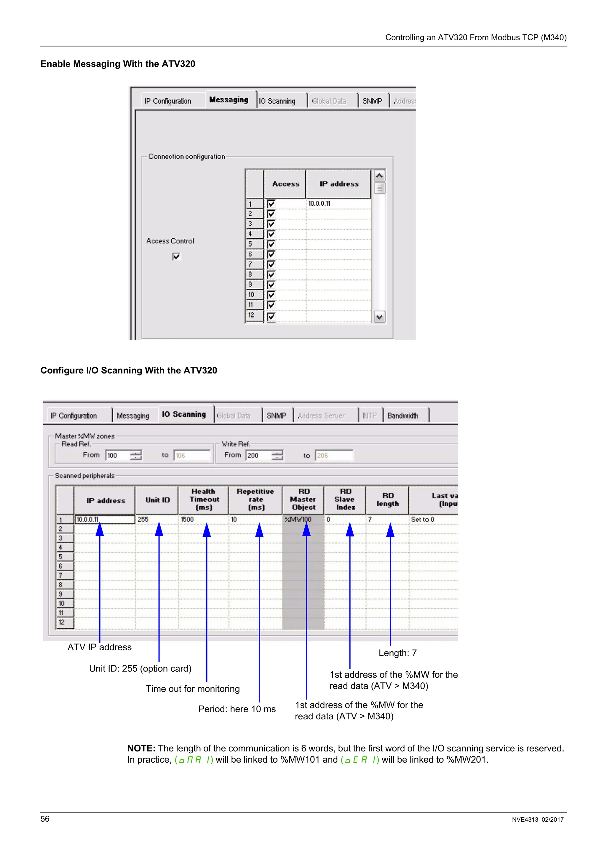
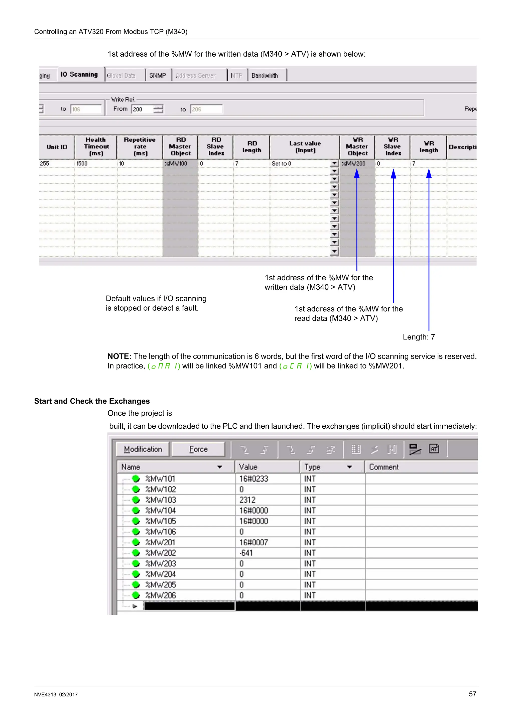
Configuring I/O Scanning
The drive I/O Scanning service can be enabled or disabled in the [Communication] (COM-) menu,
[Communication module] (Cbd-)submenu via parameter [Eth IO scan act] (IOSA).
It is not possible to modify the assignment of the I/O Scanning periodic variables using the display terminal
(integrated or graphic). To configure I/O Scanning, use the standard Web server or the SoMove software.](https://image.slidesharecdn.com/atv320modbustcpethernetipmanualnve4131302-240821021710-4e33f5e9/75/ATV320_Modbus_TCP_EtherNet_IP_Manual_NVE41313_02-pdf-29-2048.jpg)
![Configuration and Parameters
30 NVE4313 02/2017
FDR Settings
The parameters are accessible via [Configuration] (COnF-), [Full] (FULL-), [Communication]
(COM-) menu and [Communication module] (Cbd-) submenu.
The following table describes the parameters related to the “Fast device replacement settings”. More
information about FDR settings can be found in “FDR Settings” on page 103
NOTE: During the application of the configuration, the option use the File Transfer mechanism (FTP) and
some system services. If all the transfers are well finished, the operational state is reached. If the configuration
is ok: the operational state is reached, else if the configuration is not ok: the unconfigured state is reached
(FDR error #14).
Parameter Description
(HMI mnemonic)
Range or Listed Values Default Long
Name
Short
Name
Access Parameter
Number
[IP FDR] (IPF)
(IPF1) (IPF2) (IPF3)
(IPF4)
These fields displays the served
address of the FDR server
0 to 255 for each 4 fields 0.0.0.0 [0.0.0.0] (0)
(0)
(0)
(0)
R/W 64224
64225
64226
64227
[FDR Activation] (FdrU)
Enable FDR service
0: no
1: yes
yes [No]
[Yes]
(nO)
(YES)
R/W 64228
[Ethernet local conf] (LCFG)
Selection of local or server
configuration
0: no
1: yes
no [No]
[Yes]
(nO)
(YES)
R/W 64238
[FDR file error] (FdrF)
Enable FDR error management
0: no
1: yes
yes [No]
[Yes]
(nO)
(YES)
R/W 64240
[FDR Action] (FdrA) NOT ACTIVE: No command
SAVE: save command
REST: download command
DEL: delete command
IDLE [NOT
ACTIVE]
[SAVE]
[REST]
[DEL]
(IdLE)
(SAUE)
(rESt)
(dEL)
R/W 64229
[FDR Autosave] (FdrS)
Interval for periodic saving of the
FDR service
0: no
1: yes
no [No]
[Yes]
(nO)
(YES)
R/W 64230
[FDR Autosave Timer] (Fdrt) 0 to 9999 minutes 0 [0] (0) R/W 64231
[FDR Status] (FdrE)
FDR service status
- NOT ACTIVE: idle state
- INIT: initialisation
- CONF: configuration
- RDY: ready
- GET: download the current configuration
- SET: save the current configuration
- APP: Write the FDR server conf. to the drive
- OPE: operational
- UCFG: not configured
IDLE [NOT
ACTIVE]
[INIT]
[CONF]
[RDY]
[GET]
[SET]
[APP]
[OPE]
[UCFG]
(IdLE)
(INIt)
(CONF)
(rdY)
(GEt)
(SEt)
(APP)
(OPE)
(UCFG)
RW 64232
[FDR Error Code] (Fdrd) - 0: No error
- 2: the FDR configuration file is not
compatible with the drive type
- 3: Detected error reading the FDR
configuration file on the server
- 4: Detected error writing the configuration
file to the server
- 7:Time out for receipt of the FDR
configuration file from the server
- 9: duplicated IP address.
- 12:the FDR configuration file is missing
- 13: the FDR configuration file deployment
on the drive has detected an error (local
detected error)
- 14: the configuration file delete request has
detected an error on the FDR server
0 [0]
[2]
[3]
[4]
[7]
[9]
[12]
[13]
[14]
(0)
(2)
(3)
(4)
(7)
(9)
(12)
(13)
(14)
R 64233](https://image.slidesharecdn.com/atv320modbustcpethernetipmanualnve4131302-240821021710-4e33f5e9/75/ATV320_Modbus_TCP_EtherNet_IP_Manual_NVE41313_02-pdf-30-2048.jpg)
![Configuration and Parameters
NVE4313 02/2017 31
EtherNet/IP Settings
The parameters are accessible via [Configuration] (COnF-), [Full] (FULL-), [Communication]
(COM-) menu and [Communication module] (Cbd-) submenu.
These settings are only visible when the parameter [Ethernet protocol] (EtHM) is defined on
[EthernetIP] (EtIP):
Parameter Description
(HMI mnemonic)
Range or Listed Values Default Long Name Short
Name
Access Parameter
Number
[MAC @] (MAC)
MAC address display
[00-80-F4-XX-XX-XX] - [00-80-F4-XX-XX-XX] 0080
F4---
XX
XXXX
R 64267
64268
64269
[Rate setting] (rdS) 0: Autodetect
1: 10 Mbps Full
2: 10 Mbps Half
3: 100 Mbps Full
4: 100 Mbps Half
Auto [Auto]
[10M. full]
[10M. half]
[100M. full]
[100M. half]
(AUtO)
(10F)
(10H)
(100F)
(100H)
R/W 64251
[Ethernet protocol] (EthM) 0:Modbus TCP
1:EtherNet/IP
0 [Modbus TCP]
[EthernetIP]
(MbtP)
(EtIP)
R/W 64241
[IP mode] (IpM)
Use this parameter to select the IP
address assignment method
0: Man
1: BOOTP
2: DHCP
DHCP [fixed]
[BOOTP]
[DHCP]
(MAnU)
(bOOt)
(dHCP)
R/W 64250
[IP Module] (IPC)
(IPC1) (IPC2) (IPC3)
(IPC4) These fields are editable
when IP mode is set to Fixed
address
0 to 255 for each 4 fields 0.0.0.0 [0.0.0.0] (0)
(0)
(0)
(0)
R/W 64212
64213
64214
64215
[IP Gate] (IPG)
(IPG1) (IPG2) (IPG3)
(IPG4)
These fields are editable when IP
mode is set to Fixed address
0 to 255 for each 4 fields - [0.0.0.0] (0)
(0)
(0)
(0)
R/W 64220
64221
64222
64223
[Conf. Assembly] (CIO2)
Configured output assembly
20,21,100, 101 20 [20] - R -
[Services] (EWE-)
Enable web services
0: No web services
1: Web server enabled
1 - - R/W -
[Scan.Out1 address] (OCA1) Eligible modbus address CMD [OCA1] (OCA1) R/W 15421
[Scan.Out2 address] (OCA2) Eligible modbus address LFRD [OCA2] (OCA2) R/W 15422
[Scan.Out3 address] (OCA3) Eligible modbus address 0 [OCA3] (OCA3) R/W 15423
[Scan.Out4 address] (OCA4) Eligible modbus address 0 [OCA4] (OCA4) R/W 15424
[Scan.Out5 address] (OCA5) Eligible modbus address 0 [OCA5] (OCA5) R/W 15425
[Scan.Out6 address] (OCA6) Eligible modbus address 0 [OCA6] (OCA6) R/W 15426
[Scan. IN1 address] (OMA1) Eligible modbus address ETA [OMA1] (OMA1) R/W 15401
[Scan. IN2 address] (OMA2) Eligible modbus address RFRD [OMA2] (OMA2) R/W 15402
[Scan. IN3 address] (OMA3) Eligible modbus address 0 [OMA3] (OMA3) R/W 15403
[Scan. IN4 address] (OMA4) Eligible modbus address 0 [OMA4] (OMA4) R/W 15404
[Scan. IN5 address] (OMA5) Eligible modbus address 0 [OMA5] (OMA5) R/W 15405
[Scan. IN6 address] (OMA6) Eligible modbus address 0 [OMA6] (OMA6) R/W 15406
[InternCom Error1] (ILF1)
Communication interruption
between option card 1 and drive
Eligible modbus address 0 [-] (-) R/W 7134
[Fieldbus Com Interrupt] (CnF)
Communication module error
Eligible modbus address 0 [-] (-) R/W 7132](https://image.slidesharecdn.com/atv320modbustcpethernetipmanualnve4131302-240821021710-4e33f5e9/75/ATV320_Modbus_TCP_EtherNet_IP_Manual_NVE41313_02-pdf-31-2048.jpg)
![Configuration and Parameters
32 NVE4313 02/2017
Monitoring of Communication Channels
Command and Reference Channels
All the drive's command and reference parameters are managed on a channel-by-channel basis.
It is possible to identify the last value written for each channel and each command or reference parameter:
Network Monitoring Criteria
The network is monitored according to the protocol-specific criteria.
Monitoring of Communication Channels
Communication channels are monitored if they are involved in one of the following parameters:
• The control word ([Cmd Register] (CMd)) from the active command channel
• The control word containing the command switch (bit configured on [Command Switching] (CCS))
• The control word containing the switch for reference 1'1B (bit configured on [Ref 1B switching] (rCb))
• The control word containing the switch for reference 1'2 (bit configured on [Freq Switch Assign] (rFC))
• The frequency or speed reference ([Ref Frequency] (LFr) or LFRD: Nominal speed value) from the
active reference channel
• Summing frequency or speed reference ([Ref Frequency] (LFr) or LFRD: Nominal speed value) 2
(assigned to [Summing Input 2] (SA2))
• Summing frequency or speed reference ([Ref Frequency] (LFr) or LFRD: Nominal speed value) 3
(assigned to [Summing Input 3] (SA3))
• Subtracting frequency or speed reference ([Ref Frequency] (LFr) or LFRD: Nominal speed value) 2
(assigned to [Subtract Ref Freq 2] (dA2))
• Subtracting frequency or speed reference ([Ref Frequency] (LFr) or LFRD: Nominal speed value) 3
(assigned to [Subtract Ref Freq 3] (dA3))
• The PID regulator reference (PISP)
• The PID regulator feedback ([AI Virtual 2] (AIU2))
• The reference multiplication coefficient ([Multiplying coeff.] (MFr)) 2 (assigned to
[Ref Freq 2 Multiply] (MA2))
• The reference multiplication coefficient ([Multiplying coeff.] (MFr)) 3 (assigned to
[Ref Freq 3 Multiply] (MA3))
As soon as one of these parameters has been written once to a communication channel, it activates monitoring
for that channel.
If a communication alarm is sent (in accordance with the protocol criteria) by a monitored port or network card,
the drive will trigger a communication interruption.
The drive reacts according to the communication interruption configuration (detected fault, maintenance,
fallback, etc.)
Parameter name Parameter code
Taken into account
by the drive
Modbus CANopen Communication card
Control word (CMd) (CMd1) (CMd2) (CMd3)
Extended control word (CMI) (CMI1) (CMI2) (CMI3)
Speed reference (rpm) (LFrd) (LFd1) (LFd2) (LFd3)
Frequency reference
(0.1 Hz)
(LFr) (LFr1) (LFr2) (LFr3)
PI regulator reference (PISP) (PIr1) (PIr2) (PIr3)
Analog multiplier
reference
(MFr) (MFr1) (MFr2) (MFr3)
Protocol Criteria Related detected fault
Integrated Modbus
port
Adjustable time-out for received requests destined for
the drive.
[Modbus Com Interruption] (SLF)
Ethernet card FDR detected fault
IP address duplication detected fault
Adjustable time-out for received control word
(I/O scanning or messaging)
Network overload
[Fieldbus Error] (EPF2)
[Fieldbus Com Interrupt] (CNF)](https://image.slidesharecdn.com/atv320modbustcpethernetipmanualnve4131302-240821021710-4e33f5e9/75/ATV320_Modbus_TCP_EtherNet_IP_Manual_NVE41313_02-pdf-32-2048.jpg)
![Configuration and Parameters
NVE4313 02/2017 33
If a communication alarm occurs on a channel that is not being monitored, the drive will not trigger a
communication interruption.
Enabling of Communication Channels
A communication channel is enabled once all the parameters involved have been written at least one time.
The drive is only able to start if all channels involved in command and reference are enabled.
Example:
A drive in DSP402 profile is connected to an active communication channel.
It is mandatory to write at least one time the reference and the command in order to switch from “4-Switched
on” to “5-Operation enabled” state
A communication channel is disabled:
• In the event of a communication alarm
• In “forced local“ mode.
Note: On exiting “forced local“ mode:
• The drive copies the run commands, the direction and the forced local reference to the active channel
(maintained).
• Monitoring of the active command and reference channels resumes following a time delay
[Time-out forc. local] (FLOt).
• Drive control only takes effect once the drive has received the reference and the command from the active
channel.](https://image.slidesharecdn.com/atv320modbustcpethernetipmanualnve4131302-240821021710-4e33f5e9/75/ATV320_Modbus_TCP_EtherNet_IP_Manual_NVE41313_02-pdf-33-2048.jpg)
![Configuration of the Drive Commands Settings
NVE4313 02/2017 35
Configuration of the Drive for Operation in I/O Profile
To illustrate the I/O Profile, we will describe a simple example, which can be of course extended with additional
features. The Command word is made of Run forward (bit 0 of CMd), run reverse (bit 1 of CMd), and a
detected fault reset (bit 7 of CMd).
The settings will be the following:
The bits of the command word must now be configured.
In the [Inputs / Outputs] Menu, configure:
In the [Monitoring] menu, [Fault reset] submenu, configure:
[Ref Freq 1 Config] (Fr1) [Ref.Freq-Rmt.Term] (LCC) (for
example)
[Reverse Disable] (rIn) Default
[Stop Key Enable] (PSt) Default
[Control Mode] (CHCF) [I/O profile] (IO)
[Command Switching] (CCS) Default
[Cmd channel 1] (Cd1) [Com. Module] (nEt)
[Forward] (Frd) [Cd00] (Cd00)
[Reverse Assign] (rrS) [Cd01] (Cd01)
[Fault Reset Assign] (rSF) [Cd07] (Cd07)
Reset
Run reverse
Run forward
[Inputs / Outputs] / [Forward] is
assigned to CMD bit 0
[Inputs / Outputs] / [Reverse
Assign] is assigned to CMd bit 1
[Monitoring] / [Fault Reset] /
[Fault Reset Assign] is assigned
to CMd bit 7](https://image.slidesharecdn.com/atv320modbustcpethernetipmanualnve4131302-240821021710-4e33f5e9/75/ATV320_Modbus_TCP_EtherNet_IP_Manual_NVE41313_02-pdf-35-2048.jpg)
![Configuration of the Drive Commands Settings
36 NVE4313 02/2017
Configuration of the Drive for Operation With CiA402 Profile in Combined Mode
This chapter describes how to configure the settings of the drive if it is controlled in CiA402 Mode. The example
focuses on the Not separate mode (Combined). Additional modes such as the separate Mode are detailed in
the ATV320 Programming manual.
In the Command Menu [Command] (CtL-):
• [Ref Freq 1 Config] (Fr1): is set according to the communication source you can choose in the following
table:
• [Control Mode] (CHCF): defines if the drive operates in combined mode (reference and command from
the same channel).
Configuration of the Drive for Operation With CiA402 Profile in Separate Mode
Alternate combinations are possible, see the ATV320 programming manual for the list of possible settings.
Example:
The drive is controlled from the communication (EtherNet) but the reference is adjusted on the local HMI. The
control word comes from the controller and is written according to CiA402 profile.
The settings will be as follows:
Origin of the control Ref1 Channel setting
EtherNet/IP - Modbus TCP [Ref. Freq-Com. Module] (nEt)
[Ref Freq 1 Config] (Fr1) [AI virtual 1] (AIU1)
[Reverse Disable] (rIn) Default
[Stop Key enable] (PSt) Default
[Control Mode] (CHCF) [Separate] (SEp)
[Command switching] (CCS) Default
[Cmd channel 1] (Cd1) [Com. module] (nEt)
Control Word
Speed
reference](https://image.slidesharecdn.com/atv320modbustcpethernetipmanualnve4131302-240821021710-4e33f5e9/75/ATV320_Modbus_TCP_EtherNet_IP_Manual_NVE41313_02-pdf-36-2048.jpg)
![Transport Layer Protocols
40 NVE4313 02/2017
DHCP frame fields are described as follows:
DHCP messages
The DHCP protocol uses 8 different types of message during the IP assigning process.
The following table describes the 8 messages:
Operating mode
The choice between DHCP, BOOTP and manual configuration is made through one parameter:
• Manual mode: the VW3A3616 uses the address stored in parameter.
• BOOTP: card receives the addresses from BOOTP server.
• DHCP: if the Altivar Device name [XXX] is a valid name, the VW3A3616 receives the addresses from the
DHCP server.
Field Description
op Message type DHCP Request / DHCP Reply
htype Address hardware type
hlen Hardware address length
hops Used by relay agent
xid Transaction identifier, random number chosen by the client allowing to associate the request and the
response
secs Time in seconds since the beginning of the transaction
flags First bit used for the Broadcast reply flag
ciaddr Client IP address, only used if the client can respond to ARP request
yiaddr Client IP address, “your” IP address proposed by the server
siaddr IP address of the server
giaddr Gateway IP address, used when a relay agent needs to be crossed
sname Server Name
file Location of boot file
options Optional parameters with DHCP extensions
Message Description
DISCOVER The client tries to discover the DHCP server using a broadcast
OFFER The server proposes a configuration
REQUEST The client chooses a DHCP server and declines other offers
ACK The chosen server assigns the IP configuration
NAK The server rejects the client request
DECLINE The client declines the assigned IP configuration
RELEASE The client releases Its IP address before the end of the lease
INFORM The client asks for network information (it already has an IP address)](https://image.slidesharecdn.com/atv320modbustcpethernetipmanualnve4131302-240821021710-4e33f5e9/75/ATV320_Modbus_TCP_EtherNet_IP_Manual_NVE41313_02-pdf-40-2048.jpg)
![Modbus TCP Features
48 NVE4313 02/2017
I/O Scanning Service
The I/O scanning service is used to exchange periodic I/O data between:
• A controller or PLC (I/O scanner).
• Devices (I/O scanning servers).
This service is activated with [Eth IO scan act] (IOSA) parameter ((IOSA) = OFF by default).
This exchange is usually performed by implicit services, thus avoiding the need to program the controller
(PLC).
The I/O scanner periodically generates the Read/Write Multiple Registers (23 = 16#17) request. The I/O
scanning service operates if it has been enabled in the PLC and the drive. The drive parameters assigned to
I/O scanning have been selected by default. This assignment can be modified by configuration.
The drive I/O scanning service can also be configured by the Ethernet card Modbus server.
When the I/O scanning service has been enabled in the Altivar 320 drive:
• A TCP connection is assigned to it.
• The parameters assigned in the periodic variables are exchanged cyclically between the Ethernet card and
the drive.
• The parameters assigned to the periodic output variables are reserved for I/O scanning. They cannot be
written by other Modbus services, even if the I/O scanner is not sending its periodic output variables.
I/O Scanner Setting
The communication scanner is accessible via the following menus: [Communication] (COM-) and
[Communication module] (cbd) submenus.
The 6 output variables and the 6 input variables are assigned by means of parameters (OCA1) to (OCA6)
and (OMA1) to (OMA6). An (OCA x) or (OMA x) parameter with a value of zero is not linked to a
parameter in the drive.
These 6 parameters are described in the table below.
(OCA x) or (OMA x) defines the addresses.
Application Profile with Modbus TCP
The profiles managed with the ATV320 when it is controlled through Modbus TCP are:
• native profile (CiA402 - IEC 61800-7),
• I/O profile.
Please refer to “CiA®402 - IEC61800-7 Functional Profile” on page 79.
[Scan.Out1 address] (OCA1) (CMd)
[Scan.Out2 address] (OCA2) (LFrd)
[Scan.Out3 address] (OCA3) 0
[Scan.Out4 address] (OCA4) 0
[Scan.Out5 address] (OCA5) 0
[Scan.Out6 address] (OCA6) 0
[Scan.IN1 address] (OMA1) (EtA)
[Scan.IN2 address] (OMA2) (rFrd)
[Scan.IN3 address] (OMA3) 0
[Scan.IN4 address] (OMA4) 0
[Scan.IN5 address] (OMA5) 0
[Scan.IN6 address] (OMA6) 0](https://image.slidesharecdn.com/atv320modbustcpethernetipmanualnve4131302-240821021710-4e33f5e9/75/ATV320_Modbus_TCP_EtherNet_IP_Manual_NVE41313_02-pdf-48-2048.jpg)
![Modbus TCP Features
NVE4313 02/2017 49
Configuring Communication Detected Fault Management
The response of the drive in the event of an Ethernet communication detected fault can be configured.
It can be configured via the graphic display terminal or the integrated display terminal from the
[Monitoring] (FLt-) menu, [Fieldbus MONITORING] (CLL-) submenu, via the
[Fieldbus interrupt resp] (CLL) parameter.
The values of the [Fieldbus interrupt resp] (CLL) parameter, which trigger a drive detected fault
[Fieldbus Com Interrupt] (CnF), are:
The values of the [Fieldbus interrupt resp] (CLL) parameter, which do not trigger a drive detected fault, are:
The fallback speed can be configured in the [Monitoring] (FLt-) menu using the
[Fallback speed] (LFF) parameter.
RDY NET +0.00Hz 0A
Fieldbus MONITORING
Fieldbus interrupt resp : Freewheel
CANopen fault mgt : Freewheel
Modbus fault mgt : Freewheel
Code Quick
Value Meaning
[Freewheel] (YES) Freewheel stop (factory setting)
[Ramp stop] (rMP) Stop on ramp
[Fast stop] (FSt) Fast stop
[DC injection] (dCI) DC injection stop
Value Meaning
[Ignore] (nO) Detected fault ignored
[Per STT] (Stt) Stop according to configuration of [Type of stop] (Stt)
[fallback spd] (LFF) Change to fallback speed, maintained as long as the detected fault persists and the run
command has not been removed
[Spd maint.] (rLS) The drive maintains the speed at the time the detected fault occurred, as long as the
detected fault persists and the run command has not been removed
WARNING
LOSS OF CONTROL
If this parameter is set to nO, fieldbus communication monitoring is disabled.
• Only use this setting after a thorough risk assessment in compliance with all regulations and standards
that apply to the device and to the application.
• Only use this setting for tests during commissioning.
• Verify that communication monitoring has been re-enabled before completing the commissioning
procedure and performing the final commissioning test.
Failure to follow these instructions can result in death, serious injury, or equipment damage.](https://image.slidesharecdn.com/atv320modbustcpethernetipmanualnve4131302-240821021710-4e33f5e9/75/ATV320_Modbus_TCP_EtherNet_IP_Manual_NVE41313_02-pdf-49-2048.jpg)
![Modbus TCP Features
50 NVE4313 02/2017
CnF and ILF Detected Faults
The following table lists the time-out parameters:
Parameter Description Possible Values Terminal
Display
[Fieldbus Com
Interrupt]
(CnF)
(written to the device)
This detected fault is used to indicate that
a network detected fault has occurred.
When the detected fault occurs, the
option position the CNF parameter to the
value corresponding to the detected fault.
When the detected fault has disappeared,
the option writes the CNF parameter to 0
1: Modbus TCP timeout
10: Network overload
11: Loss of carrier
14: Ethernet/IP Scanner timeout
15: Ethernet/IP Idle Poll
16: Ethernet/IP forced EIP trip
17: Application I/O configuration
detected error
[1] (1)
[10] (10)
[11] (11)
[14] (14)
[15] (15)
[16] (16)
[17] (17)
[InternCom Error1]
(ILF)
This detected fault indicates a critical
detected error and can be cleared. It
needs a Power Off / Power On to remove
the detected fault
13: FDR uncoverable detected error
18: EEPROM detected error
21: Internal detected error
[13] (13)
[18] (18)
[21] (21)
[Fieldbus Error]
(EPF2)
8: No valid IP
9: Duplicate IP address
12: FRD unconfigured detected error
13: FDR uncoverable detected error
20: invalid drive config when
activating ODVA profile.
[8] (8)
[9] (9)
[12] (12)
[13] (13)
[20] (20)](https://image.slidesharecdn.com/atv320modbustcpethernetipmanualnve4131302-240821021710-4e33f5e9/75/ATV320_Modbus_TCP_EtherNet_IP_Manual_NVE41313_02-pdf-50-2048.jpg)
![Modbus TCP Features
NVE4313 02/2017 51
Configuring Monitor Parameters
It is possible to select up to 4 parameters to display their values in the [1.2 DISPLAY] menu on the graphic
display terminal (to be ordered separately - reference VW3A1101).
The selection is made via the [3.3 Display configuration] menu, [Com. map config.] submenu.
Each parameter, in the range [Word 1 add. select.] ... [Word 4 add. select.], can be used to select the
parameter logic address. An address at zero is used to disable the function.
Example
In the example given here, the monitored words are:
• Parameter 1 = Motor current (LCr): logic address 3204, signed decimal format.
• Parameter 2 = Motor torque (Otr): logic address 3205, signed decimal format.
• Parameter 3 = Last detected fault occurred (LFt): logic address 7121, hexadecimal format.
• Disabled parameter: Address W0; default format: Hexadecimal format
One of the three display formats below can be assigned to each monitored word:
NOTE: If a monitored parameter:
• Has been assigned to an unknown address (example: 3200).
• Has been assigned to a protected parameter.
• Has not been assigned.
the value displayed in the [Communication map] screen will be: “••••” (see “CnF and ILF Detected Faults” on
page 50).
RDY NET +0.00Hz 0A
Com. map config..
Word 1 add. select. : 3204
Format word 1 : Signed
Word 2 add. select. : 3205
Format word 2 : Signed
Word 3 add. select. : 7121
Code Quick
Format Range Terminal display
Hexadecimal 0000 ... FFFF [Hex] (HEX)
Signed decimal -32 767 ... 32 767 [Signed] (SIG)
Unsigned decimal 0 ... 65 535 [Unsigned] (nSG)](https://image.slidesharecdn.com/atv320modbustcpethernetipmanualnve4131302-240821021710-4e33f5e9/75/ATV320_Modbus_TCP_EtherNet_IP_Manual_NVE41313_02-pdf-51-2048.jpg)
![Controlling an ATV320 From Modbus TCP (M340)
54 NVE4313 02/2017
Configuration of the VW3A3616 Communication Card
Conf > Full > Communication > Communication card
Configuration of the Command
In the Command Menu [Command] (CtL):
• [Ref Freq 1 Config] (Fr1): is set according to the communication source you can choose in the following
table:
• [Reverse Disable] (rIn): default.
• [Stop Key enable] (PSt): default.
• [Control Mode] (CHCF): defines if the drives operates in combined mode (reference and command from
the same channel)
For the current example, [Control Mode] (CHCF) will be adjusted to [Not Separ.] (SIM) as reference and
control are originated from the communication network:
ETHM = MBTP Defines the protocol used: Modbus TCP
IPM = MANU IP address is defined locally
IP card = 10.0.0.11 -
IP Mask 255.0.0.0 -
IP Master = 10.0.0.10 Defines the address of the I/O scanner client
(M340 Ethernet module)
OCA1 8501 > CMD In the example we will use the default
parameters + an additional parameter for
monitoring
OCA2 8602 > LFRD
OCA3 -
OCA4 -
OCA5 -
OCA6 -
OMA1 3201 > ETA
OMA2 8604 > RFRD
OMA3 3207 > ULN
OMA4 -
OMA5 -
OMA6 -
Origin of the control Ref1 Channel setting
Modbus TCP [Com. Module] (nEt)
Profile Ref1 Channel setting
CiA402 [Not Separ.] (SIM)
Separate [Separate] (SEp)
I/O Profile [I/O Profile] (IO)](https://image.slidesharecdn.com/atv320modbustcpethernetipmanualnve4131302-240821021710-4e33f5e9/75/ATV320_Modbus_TCP_EtherNet_IP_Manual_NVE41313_02-pdf-54-2048.jpg)
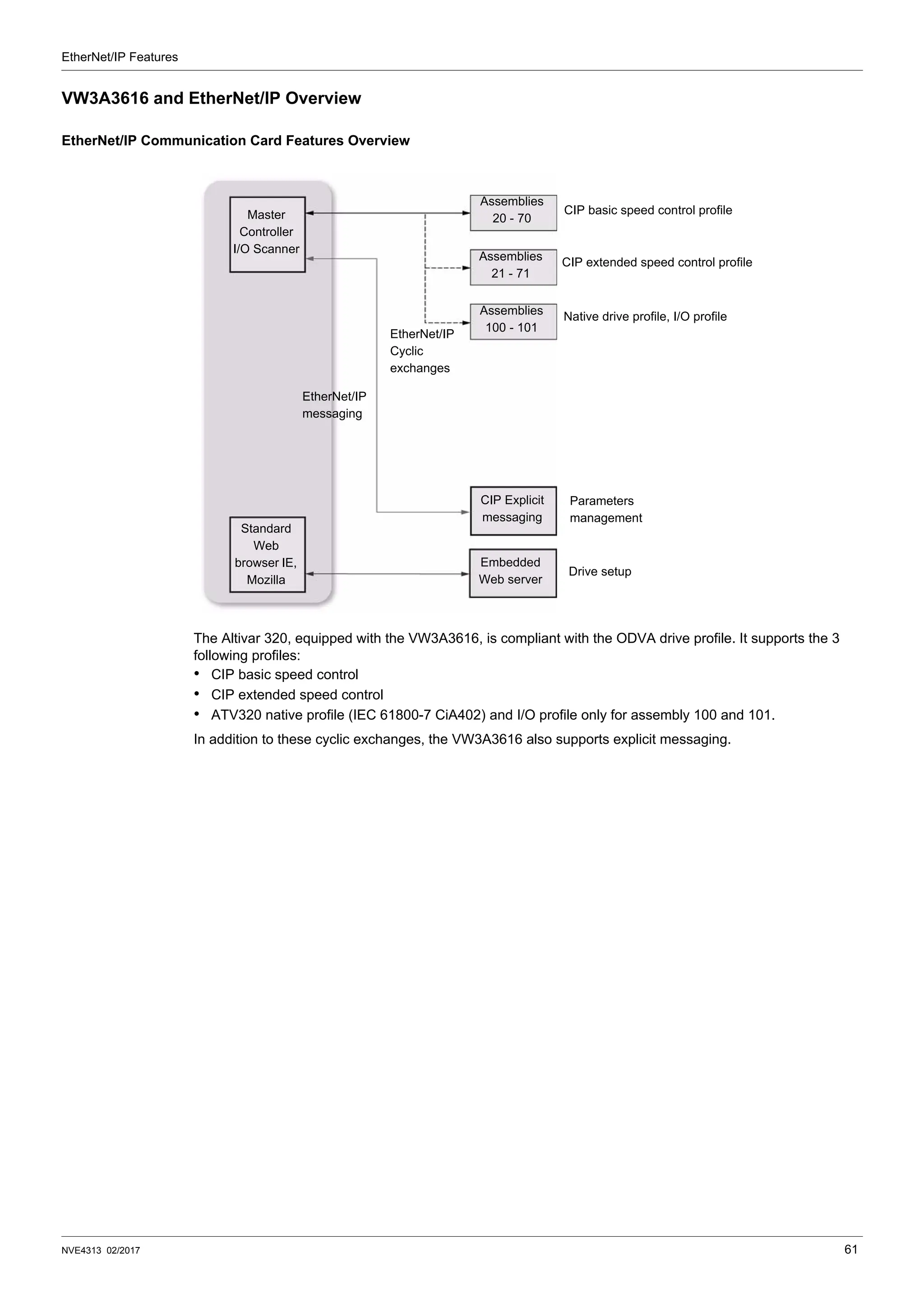
![EtherNet/IP Features
62 NVE4313 02/2017
Cyclical Exchanges (Implicit Exchanges)
Overview
This part gives a description of the 3 assembly sets and how to configure them.
Principle of Control configuration
By the configuration of the control, it is possible to decide from what channel the drive receives its commands
and setpoint, either permanently or depending on a switching command. Numerous configurations are
possible. For more information, refer to the Programming manual and Communication parameters manual.
The following configurations are some of the available possibilities.
The selection of the assembly set is made with the EtherNet/IP communication adapter.
Control With Communication Scanner
If the default assemblies (100, 101) are selected, the Altivar 320 will be controlled according to its native profile
CiA402.-IEC-61800-7 (See “CiA®402 - IEC61800-7 Functional Profile” on page 79). By configuring the
communication scanner, it is possible to assign any relevant parameter of the drive to the 6 input and 6 output
variables of the assemblies.
The size of the assembly (100, 101) is fixed and is equal to 6 words.
The mapping of the other parameters is made with the communication scanner.
The configuration of the addresses defined with (OCA x) and (OMA x) can be made with the graphic keypad:
• For assembly 100: [Communication] (COM-) menu, [Communication module] (Cbd-) submenu.
• For assembly 101: [Communication] (COM-) menu, [Communication module] (Cbd-) submenu.
See menu [1.2 DISPLAY] (MOn-) > COMMUNICATION MAP to monitor the communication scanner.
Altivar
The mapping of the 100-101 assemblies is
made with the communication scanner
(OCA1) (OMA1)
(OCA2) (OMA2)
(OCA3) (OMA3)
(OCA4) (OMA4)
(OCA5) (OMA5)
(OCA6) (OMA6)
Assembly
100
Assembly
101
Up to additional
parameters are
mapped
This configuration can be made with:
• HMI
• Keypad
• SoMove
• Webserver
EtherNet/IP option
EtherNet/IP
scanner
100-101
Native drive profile
CiA402](https://image.slidesharecdn.com/atv320modbustcpethernetipmanualnve4131302-240821021710-4e33f5e9/75/ATV320_Modbus_TCP_EtherNet_IP_Manual_NVE41313_02-pdf-62-2048.jpg)
![EtherNet/IP Features
NVE4313 02/2017 65
Network setpoint and network address management
The assembly 21 uses the setpoint and reference switching of the Altivar 320. The VW3A3616, when
configured with the assembly 21, links the bit 5 and the bit 6 to C312 and C313 respectively. To operate
correctly, the Command settings of the ATV320 must be as follows:
• Assembly 71: CIP extended speed control input
The following table describes the assembly mapping:
The following table describes the CIP extended status word:
Menu Parameter Permitted value
[Command] (CtL-)
[Application function] (FUn-)
[Ref Freq switch] (rEF-)
[Control Mode] (CHCF) [Separate] (SEP)
[Ref Freq 1 Config] (Fr1) [Com. Module] (nEt)
[Ref Freq 2 Config] (Fr2) [Al1] (AI1) or [Al2] (AI2)
[Cmd channel 1] (Cd1) [Com. module] (nEt)
[Cmd channel 2] (Cd2) [Terminals] (tEr)
[Command switching] (CCS) [C312] (C312)
[Freq switch Assign] (rFC) [C313] (C313)
Word Number Definition
0 CIP extended status word
1 Actual speed (rpm)
Bit 7 Bit 6 Bit 5 Bit 4 Bit 3 Bit 2 Bit 1 Bit 0
At reference
0= Reference
not reached
1= Reference
reached
Setpoint from
network
0= Setpoint from
terminals
1= Setpoint from
network
Command from
network
0= Command
from terminals
1= Command
from network
Ready
0= Not ready
1= Ready
Run forward / reverse
00= Stopped
01= Running forward
10= Running reverse
11= Not used
Warning
0= No
warning
1= Warning
Not used
Bit 15 Bit 14 Bit 13 Bit 12 Bit 11 Bit 10 Bit 9 Bit 8
Not used Not used Not used Not used Not used Bit 8 to 10 are used for the drive state
000= Not used
001= Startup
010= Not ready
011= Ready
100= Enabled
101= Stopping
110= Fault stop
111= Faulted](https://image.slidesharecdn.com/atv320modbustcpethernetipmanualnve4131302-240821021710-4e33f5e9/75/ATV320_Modbus_TCP_EtherNet_IP_Manual_NVE41313_02-pdf-65-2048.jpg)
![EtherNet/IP Features
NVE4313 02/2017 67
Detected Fault Management
An EtherNet/IP time out is triggered if the card does not receive any cyclic messages (within a predefined time
period).
This period is managed by the EtherNet/IP controller (not by the drive) and is configured in its module
properties box. The duration of the time out is defined by the RPI (Request packet intervals).
Configuration can be performed using the graphic display terminal or integrated display terminal using the
[Fieldbus interrupt resp] (CLL) parameter in the [Monitoring] (FLt-) menu,
[Fieldbus MONITORING] (CLL-) submenu.](https://image.slidesharecdn.com/atv320modbustcpethernetipmanualnve4131302-240821021710-4e33f5e9/75/ATV320_Modbus_TCP_EtherNet_IP_Manual_NVE41313_02-pdf-67-2048.jpg)
![ATV320 Configuration in ETC100
74 NVE4313 02/2017
Explicit Messaging
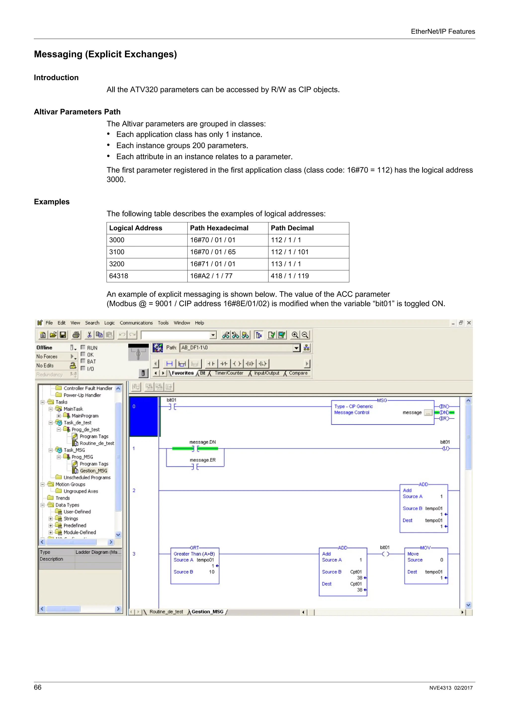
An example of explicit messaging is shown below. The value of the ACC parameter
(Modbus @ = 9001 / CIP address 16#8E:01:02).
Get Single Attribute
SEND_REQ description:
(0.2.0.1): Rack.location.way.equipment number
16#000E: messaging CIP (mandatory)
Set Single Attribute
SEND_REQ description:
(0.2.0.1): Rack.location.way.equipment number
16#000E: messaging CIP (mandatory)
(*Get single attribut*)
if not reading_diagnostic [0] .0 and %M0 then
reading_request_contents [0] :=16#0000; (*Reserved*)
reading_request_contents [1] :=16#030E; (*03 - Request length in words / 0E - Get single*)
reading_request_contents [2] :=16#8E20; (*Class*)
reading_request_contents [3] :=16#0124; (*Instance*)
reading_request_contents [4] :=16#0230; (*Attribut*)
reading_diagnostic [3] :=16#0A; (*Fixed size of request in bytes*)
SEND_REQ (addr(‘0.2.0.1’),16#000E,reading_request_contents,reading_diagnostic,reading_results);
%M0:=False
End_if;
(*Set single attribut*)
if not writing_diagnostic [0] .0 and %M1 then
writing_request_contents [0] :=16#0000; (*Reserved*)
writing_request_contents [1] :=16#0310; (*03 - Request length in words / 10 - SET single*)
writing_request_contents [2] :=16#8E20; (*Class*)
writing_request_contents [3] :=16#0124; (*Instance*)
writing_request_contents [4] :=16#0230; (*Attribut*)
writing_request_contents [5] :=35; (*value to write*)
writing_diagnostic [3] :=16#0c; (*size of request in bytes*)
SEND_REQ (addr(‘0.2.0.1’),16#000E,writing_request_contents,writing_diagnostic,writing_results);
%M1:=False
End_if;](https://image.slidesharecdn.com/atv320modbustcpethernetipmanualnve4131302-240821021710-4e33f5e9/75/ATV320_Modbus_TCP_EtherNet_IP_Manual_NVE41313_02-pdf-74-2048.jpg)
![ATV320 Configuration in ETC100
NVE4313 02/2017 75
Get All Attribute
SEND_REQ description:
(0.2.0.1): Rack.location.way.equipment number
16#000E: messaging CIP (mandatory)
Set All Attribute
SEND_REQ description:
(0.2.0.1): Rack.location.way.equipment number
16#000E: messaging CIP (mandatory)
(*Get all attribut*)
if not reading_diagnostic_all [0] .0 and %M2 then
reading_request_contents_all [0] :=16#0000; (*Reserved*)
reading_request_contents_all [1] :=16#0201; (*02 - Request length in words / 01 - Get All*)
reading_request_contents_all [2] :=16#8E20; (*Class*)
reading_request_contents_all [3] :=16#0124; (*Instance*)
reading_diagnostic_all [3] :=16#08; (*Fixed size of request in bytes*)
SEND_REQ
(addr(‘0.2.0.1’),16#000E,reading_request_contents_all,reading_diagnostic_all,reading_results_all);
%M2:=False
End_if;
(*Set all attribut*)
if not reading_diagnostic_all [0] .0 and %M3 then
writing_request_contents_all [0] :=16#0000; (*Reserved*)
writing_request_contents_all [1] :=16#0202; (*02 - Request length in words / 02 - SET All*)
writing_request_contents_all [2] :=16#8E20; (*Class*)
writing_request_contents_all [3] :=16#0124; (*Instance*)
writing_diagnostic_all [3] :=16#2A; (*size of request in bytes*)
SEND_REQ
(addr(‘0.2.0.1’),16#000E,writing_request_contents_all,writing_diagnostic_all,writing_results_all);
%M3:=False
End_if;](https://image.slidesharecdn.com/atv320modbustcpethernetipmanualnve4131302-240821021710-4e33f5e9/75/ATV320_Modbus_TCP_EtherNet_IP_Manual_NVE41313_02-pdf-75-2048.jpg)
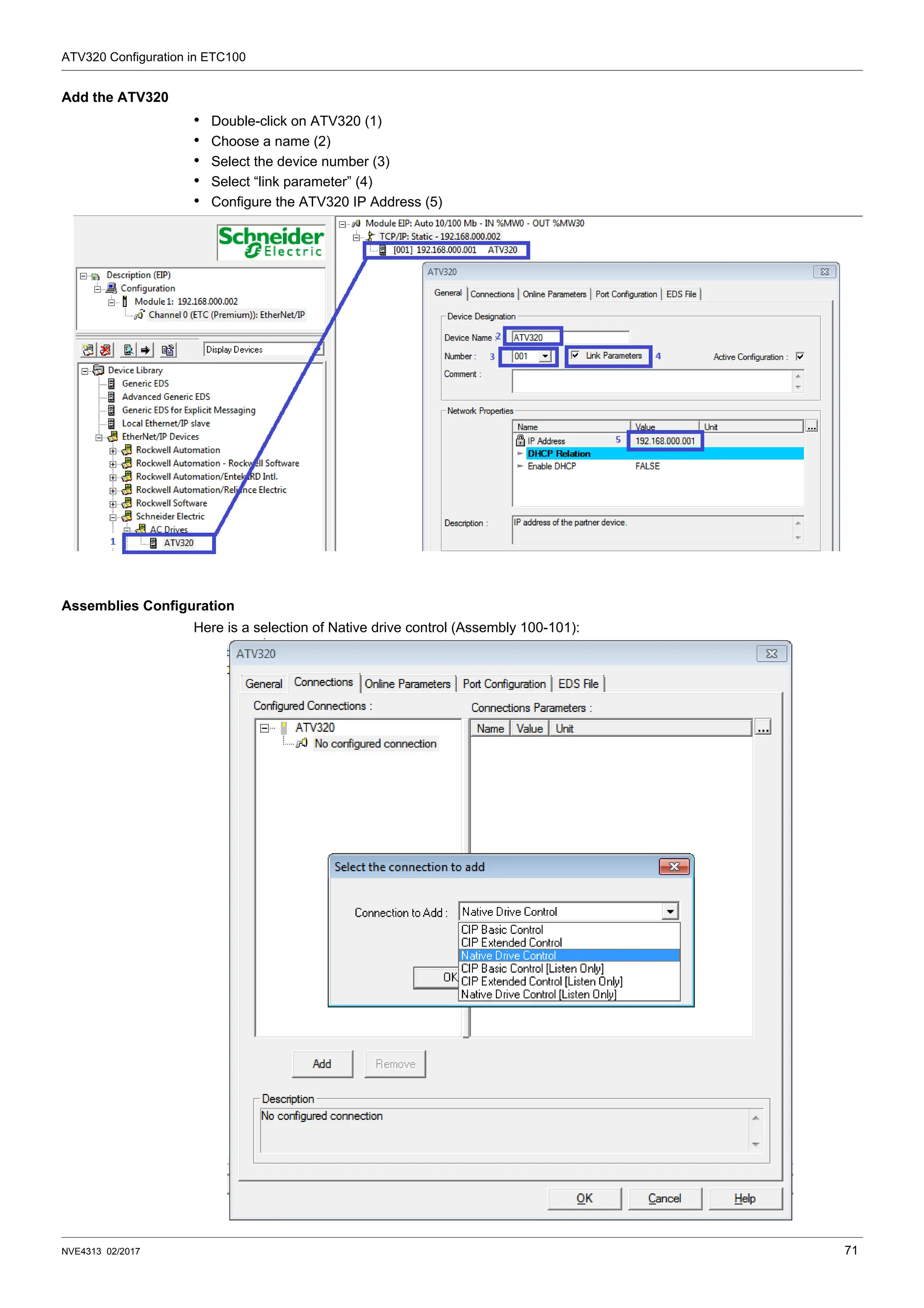
![Profiles
78 NVE4313 02/2017
Functional Profiles Supported by the Altivar 320
I/O Profile
Using the I/O profile simplifies PLC programming.
The I/O profile mirrors the use of the terminal strip for control by utilizing 1 bit to control a function.
With an Altivar 320, the I/O profile can also be used when controlling via a network.
The drive starts up as soon as the run command is sent.
15 bits of the control word (bits 1 to 15) can be assigned to a specific function.
This profile can be developed for simultaneous control of the drive via:
• The terminals
• The Modbus control word
• The CANopen control word
• The network module control word
The I/O profile is supported by the drive itself and therefore in turn by all the communication ports (integrated
Modbus, CANopen, Ethernet, Profibus DP, DeviceNet communication modules).
CiA402 Profile
The drive only starts up following a command sequence.
The control word is standardized.
5 bits of the control word (bits 11 to 15) can be assigned to a function.
The CiA402 profile is supported by the drive itself and therefore in turn by all the communication ports
(integrated Modbus, CANopen, Ethernet, Profibus DP, DeviceNet communication modules).
The Altivar 320 supports the CiA402 profile’s “Velocity mode”.
In the CiA402 profile, there are two modes that are specific to the Altivar 320 and characterize command and
reference management:
• Separate mode [Separate] (SEP)
• Not separate mode [Not separ.] (SIM)
See “CiA®402 - IEC61800-7 Functional Profile” on page 79.](https://image.slidesharecdn.com/atv320modbustcpethernetipmanualnve4131302-240821021710-4e33f5e9/75/ATV320_Modbus_TCP_EtherNet_IP_Manual_NVE41313_02-pdf-78-2048.jpg)
![CiA®402 - IEC61800-7 Functional Profile
82 NVE4313 02/2017
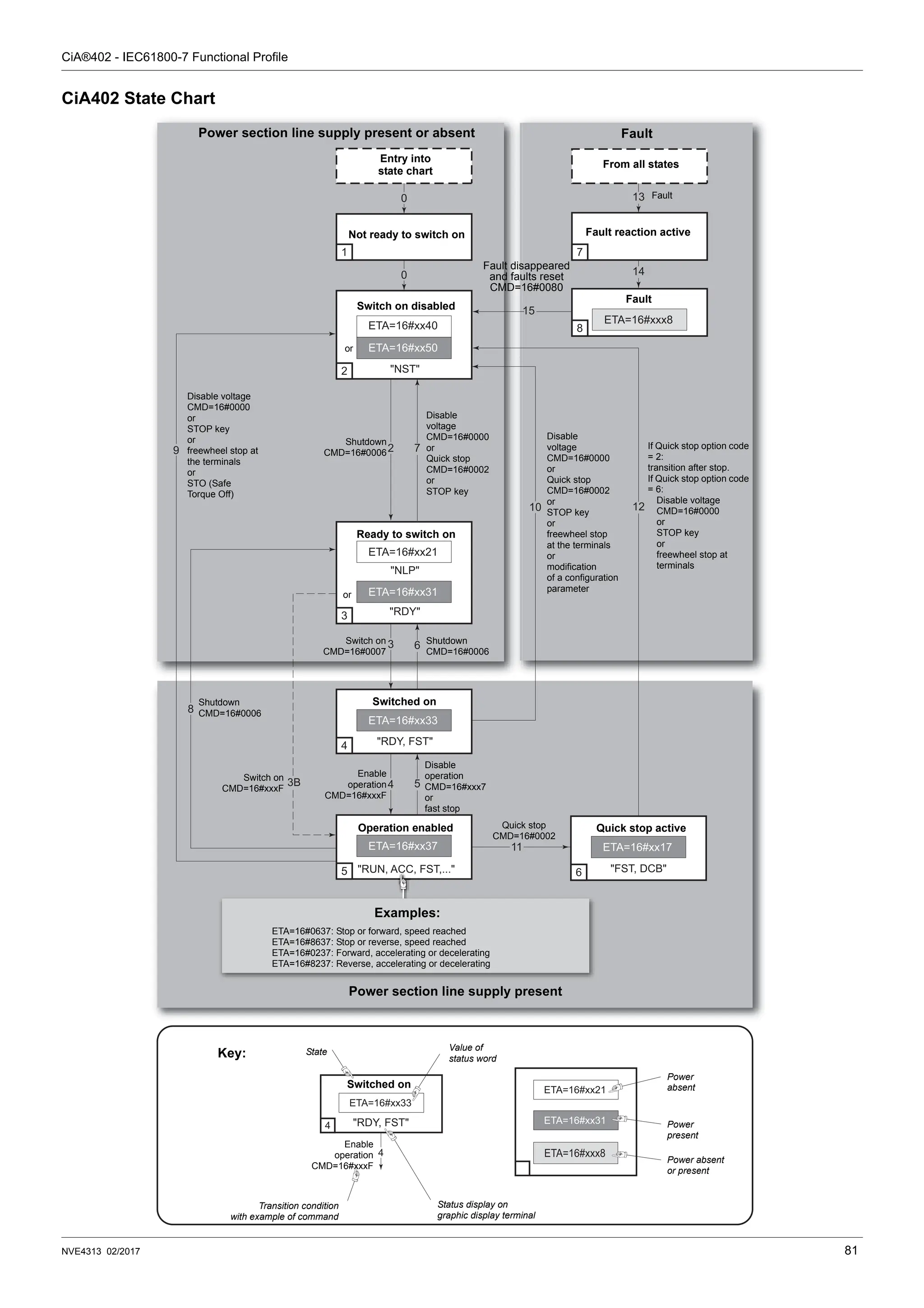
Description of States
Each state represents an internal reaction by the drive.
This chart will change depending on whether the control word is sent (CMd) or an event occurs (a detected
fault, for example).
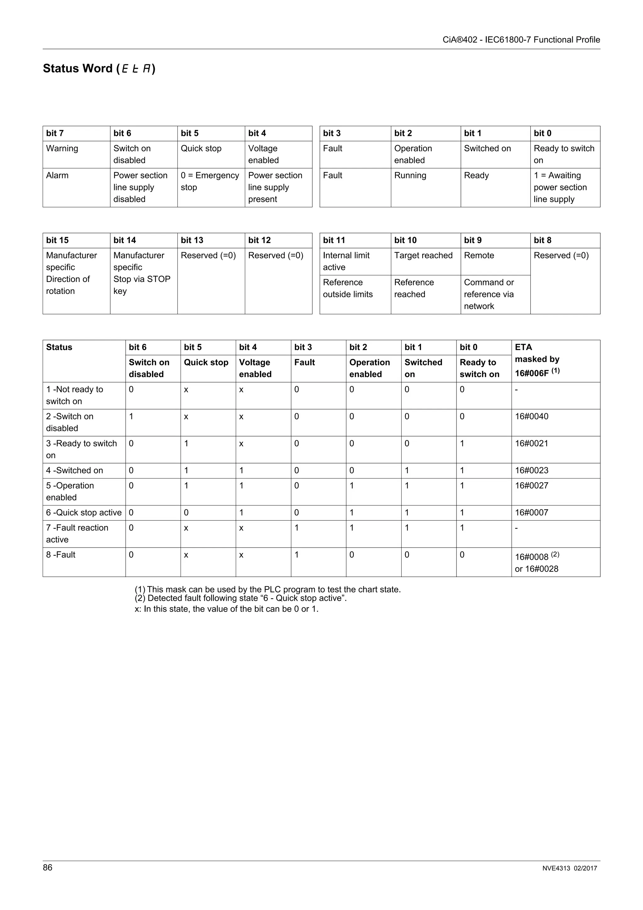
The drive state can be identified by the value of the status word (EtA).
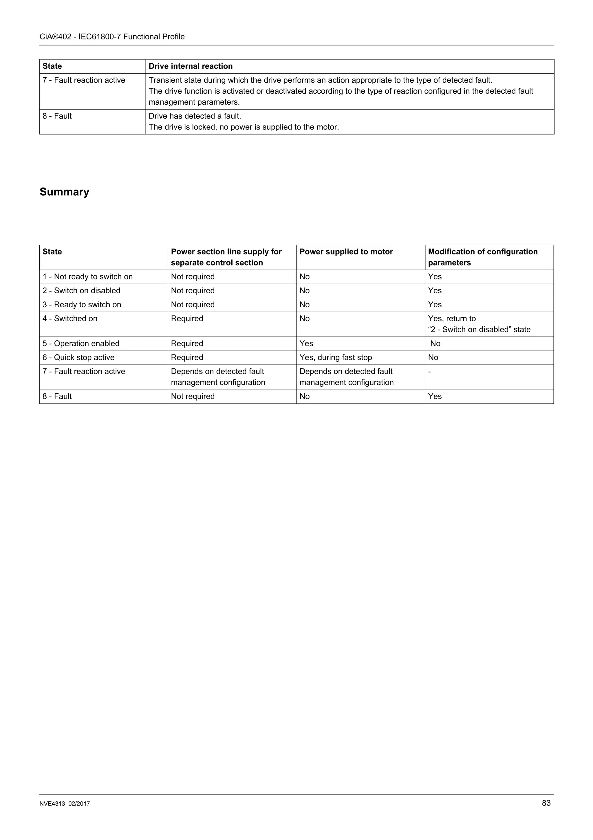
State Drive internal reaction
1 - Not ready to switch on Initialization starts. This is a transient state invisible to the communication network.
2 - Switch on disabled The drive is inactive.
The drive is locked, no power is supplied to the motor.
For a separate control section, it is not necessary to supply AC power to the power section.
For a separate control section with line contactor, the contactor is not controlled.
The configuration and adjustment parameters can be modified.
3 - Ready to switch on Awaiting power section line supply.
For a separate control section, it is not necessary to supply AC power to the power section, but the system will expect
it in order to change to state “4 - Switched on”.
For a separate control section with line contactor, the contactor is not controlled.
The drive is locked, no power is supplied to the motor.
The configuration and adjustment parameters can be modified.
4 - Switched on The drive is supplied with AC power but is stationary.
For a separate control section, the power section line supply must be present.
For a separate control section with line contactor, the contactor is controlled.
The drive is locked, no power is supplied to the motor.
The power stage of the drive is ready to operate, but voltage has not yet been applied to the output.
The adjustment parameters can be modified.
Modification of a configuration parameter returns the drive to state “2 - Switch on disabled”.
5 - Operation enabled The drive is running.
For a separate control section, the power section line supply must be present.
For a separate control section with line contactor, the contactor is controlled.
The drive is unlocked, power is supplied to the motor.
The drive functions are activated and voltage is applied to the motor terminals.
If the reference is zero or the “Halt” command is applied, no power is supplied to the motor and no torque is applied.
[Auto tuning] (tUn) requires an injection of current into the motor. The drive must therefore be in state
“5 - Operation enabled” for this command.
The adjustment parameters can be modified.
The configuration parameters cannot be modified.
NOTE: The command “4 - Enable operation” must be taken into consideration only if the channel is valid. In
particular, if the channel is involved in the command and the reference, transition 4 will take place only after the
reference has been received for the first time.
The reaction of the drive to a “Disable operation” command depends on the value of the
[Dis. operat opt code] (dOtd) parameter:
- If the [Dis. operat opt code] (dOtd) parameter has the value 0, the drive changes to “4 - Switched on” and
stops in freewheel stop.
- If the [Dis. operat opt code] (dOtd) parameter has the value 1, the drive stops on ramp and then changes
to “4 - Switched on”.
6 - Quick stop active Emergency stop.
The drive performs a fast stop, after which restarting will only be possible once the drive has changed to the
“Switch on disabled” state.
During fast stop, the drive is unlocked and power is supplied to the motor.
The configuration parameters cannot be modified.
The condition for transition 12 to state “2 - Switch on disabled” depends on the value of the parameter Quick stop
mode (QStd):
If the Quick stop mode parameter has the value FST2, the drive stops according to the fast stop ramp and then
changes to state “2 - Switch on disabled”.
If the Quick stop mode parameter has the value FST6, the drive stops according to the fast stop ramp and then
remains in state “6 - Quick stop active” until:
- A “Disable voltage” command is received.
- Or the STOP key is pressed.
- Or there is a freewheel stop command via the terminals.](https://image.slidesharecdn.com/atv320modbustcpethernetipmanualnve4131302-240821021710-4e33f5e9/75/ATV320_Modbus_TCP_EtherNet_IP_Manual_NVE41313_02-pdf-82-2048.jpg)
![CiA®402 - IEC61800-7 Functional Profile
NVE4313 02/2017 85
Stop Commands
The “Halt” command enables movement to be interrupted without having to leave the “5 - Operation enabled”
state. The stop is performed in accordance with the [Type of stop] (Stt) parameter.
If the “Halt” command is active, no power is supplied to the motor and no torque is applied.
Regardless of the assignment of the [Type of stop] (Stt) parameter ([Fast stop assign] (FSt),
[Ramp stop] (rMP), [Freewheel] (nSt), or [DC injection assign.] (dCI)), the drive remains in the “5 -
Operation enabled” state.
A Fast Stop command at the terminals or using a bit of the control word assigned to Fast Stop causes a change
to the “4 - Switched on” state. A “Halt” command does not cause this transition.
A Freewheel Stop command at the terminals or using a bit of the control word assigned to Freewheel Stop
causes a change to the “2 - Switch on disabled” state. A “Halt” command does not cause this transition.
Assigning Control Word Bits
In the CiA402 profile, fixed assignment of a function input is possible using the following codes:
For example, to assign the DC injection braking to bit 13 of Ethernet, simply configure the
[DC injection assign.] (dCI) parameter with the [C313] (C313) value.
Bit 11 is assigned by default to the operating direction command [Reverse Assign] (rrS).
Bit Network module
bit 11 C311
bit 12 C312
bit 13 C313
bit 14 C314
bit 15 C315](https://image.slidesharecdn.com/atv320modbustcpethernetipmanualnve4131302-240821021710-4e33f5e9/75/ATV320_Modbus_TCP_EtherNet_IP_Manual_NVE41313_02-pdf-85-2048.jpg)
![CiA®402 - IEC61800-7 Functional Profile
92 NVE4313 02/2017
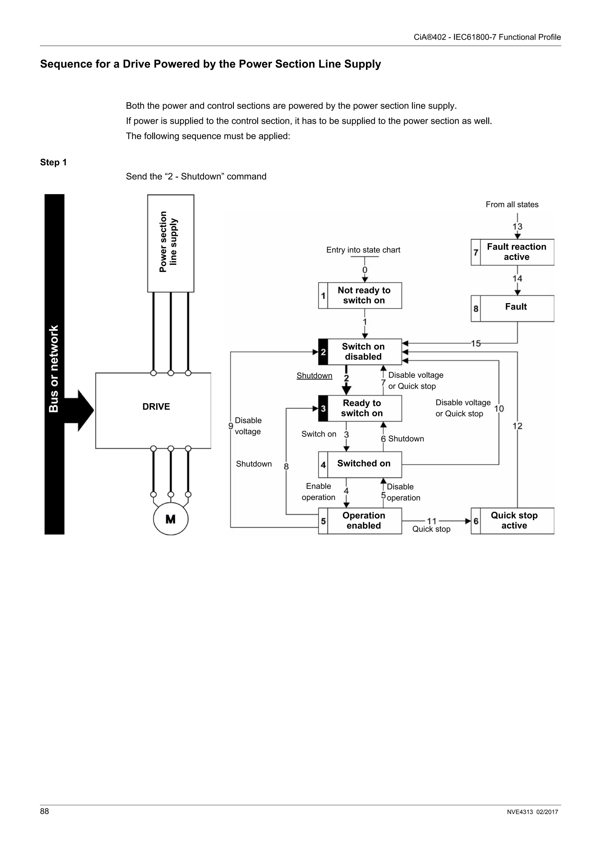
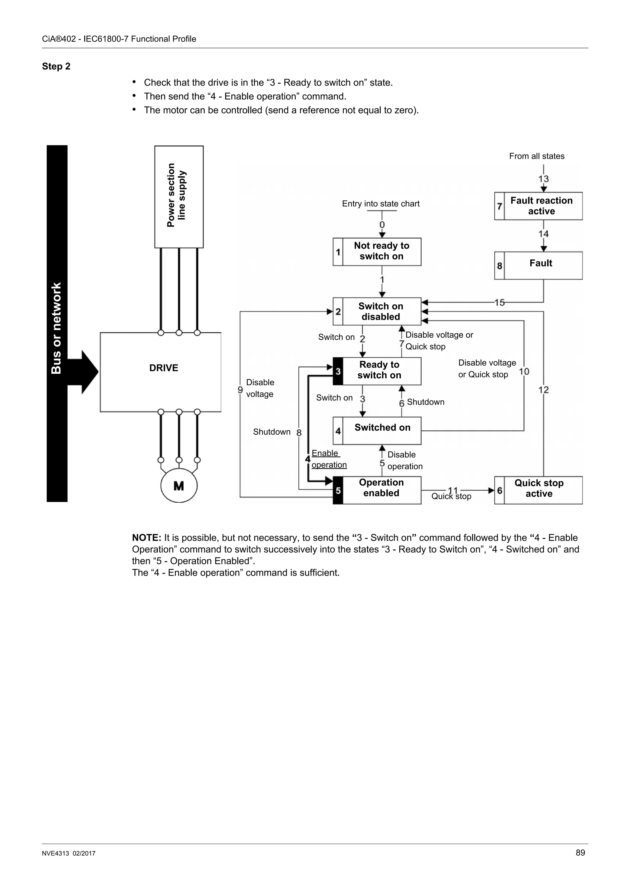
Step 3
• Check that the drive is in the “4 - Switched on” state.
• Then send the “4 - Enable operation” command.
• The motor can be controlled (send a reference not equal to zero).
• If the power section line supply is still not present in the “4 - Switched on” state after a time delay
[Mains V. time out] (LCt), the drive triggers an error [Input Contactor] (LCF).
DRIVE
Power
section
line
supply
Bus
or
network
Control
section
power
supply
Entry into state chart
From all states
Not ready to
switch on
Fault reaction
active
Fault
Switch on
disabled
Ready to
switch on
Disable voltage
or Quick stop
Shutdown
Disable
voltage
Shutdown
Switch on
Disable voltage
or Quick stop
Switched on
Operation
enabled
Quick stop
active
Disable
operation
Quick stop
Shutdown
Enable
operation](https://image.slidesharecdn.com/atv320modbustcpethernetipmanualnve4131302-240821021710-4e33f5e9/75/ATV320_Modbus_TCP_EtherNet_IP_Manual_NVE41313_02-pdf-92-2048.jpg)

![Transparent Ready Features
100 NVE4313 02/2017
Presentation
The FDR (Fast Device Replacement) service is used to simplify the maintenance of drives connected on the
Ethernet network. In the event of a drive malfunction, this service automatically reconfigure its replacement.
The new drive (FDR client) retrieves:
• its IP addresses and the FDR file path from a DHCP server
• the FDR file from an FTP server, if the drive is not configured in local configuration
In practice, the DHCP server and the FTP server are the same device (PLCs: TSX Premium, Quantum PLC
or dedicated PCs).
The FDR file contains:
• the Ethernet parameters (configuration of I/O scanning, FDR etc.)
• the drive parameters (drive, functions, application, etc.)
The FDR service is based on identification of the device by a “Device Name”. In the case of the Altivar 320
drive, this is represented by the [Device Name] (PAn) parameter.
Configuration using the drive graphic display terminal or the integrated display terminal is explained in the
“Configuration of the Drive Commands Settings” on page 34. Configuration using the standard Web server is
explained in the “Embedded Webserver” on page 107. For configuration using the SoMove software
workshop, refer to the software online help.
NOTE: Check that all the network devices do have different “Device Names”.
The FDR server controls duplication of “Device Names” (it does not assign an IP address that has already
been assigned and is active).
If the same IP address is supplied on 2 devices, the 2nd should trigger an IP address duplication (network
management detected fault which leads to a drive detected error [Fieldbus Error] (EPF2) by default).
If the FDR service has been enabled, the Ethernet card attempts to restore its IP addresses on each
power-up. Each time the procedure detects a fault, the Ethernet card reiterates its FDR requests (DHCP).
Where the configuration also needs to be downloaded by the FDR server:
After assigning the Ethernet card IP addresses, if the configuration download detects a fault, the Ethernet card
detects a network management detected fault (which leads to a drive detected fault
[Fieldbus Error] (EPF2) by default).](https://image.slidesharecdn.com/atv320modbustcpethernetipmanualnve4131302-240821021710-4e33f5e9/75/ATV320_Modbus_TCP_EtherNet_IP_Manual_NVE41313_02-pdf-100-2048.jpg)
![Transparent Ready Features
NVE4313 02/2017 101
Startup Detailed Behavior
Ready
Check stored
configuration
Operational
Apply
configuration
Copy served ->
Stored
Check served
configuration
Get configuration
(from FDR Server)
Start random timer
Check FDR
error mgt.
Unrecoverable
detected fault
Unconfigurred and
ETH detected error
[Apply NOK]
FDR error
FDR error mgt=1
[Served Conf NOK or empty]
[Local storage NOK]
[No valid response after N retries]
[Local storage OK]
[Apply OK]
[Served Conf OK]
[Access OK]
[FDR Local config=0]
[Stored
Configuration
OK]
[Stored
Configuration
NOK]
[FDR Local config=1]
[Parameter file
management supported]](https://image.slidesharecdn.com/atv320modbustcpethernetipmanualnve4131302-240821021710-4e33f5e9/75/ATV320_Modbus_TCP_EtherNet_IP_Manual_NVE41313_02-pdf-101-2048.jpg)
![Transparent Ready Features
102 NVE4313 02/2017
FDR Operation Behavior
Delete Configuration
(In FDR Server)
[Apply OK]
[Access OK]
Operational
Get configuration
(from FDR Server)
Check served
configuration
Store configuration
(on FDR Server)
(Stored -> Served)
Copy served ->
Stored
Unrecovable
detected fault
Unconfigurredand
ETH detected error
Check FDR
error mgt.
Apply device params
(Stored -> Current)
[No valid response after N retries]
[Delete performed]
[Triggered Restore]
[Triggered Deleted]
[Triggered Backup]
[Store OK]
[Served Conf OK]
[Served Conf NOK or empty]
[Local Storage OK]
[Local Storage NOK]
[No valid response after N retries]
FDR error mgt=1
FDR error mgt=0](https://image.slidesharecdn.com/atv320modbustcpethernetipmanualnve4131302-240821021710-4e33f5e9/75/ATV320_Modbus_TCP_EtherNet_IP_Manual_NVE41313_02-pdf-102-2048.jpg)
![Transparent Ready Features
NVE4313 02/2017 103
FDR Settings
The following table describes the FDR setting parameters:
NOTE: During the application of the configuration, the option use the File Transfer mechanism (FTP) and
some system services. If all the transfers are well finished, the operational state is reached. If the configuration
is ok: the operational state is reached, else if the configuration is not ok: the unconfigured state is reached
(FDR error #14).
Parameter Description
(HMI mnemonic)
Range or Listed Values Default Long
Name
Short
Name
Access Parameter
Number
[IP FDR] (IPF-)
(IPF1) (IPF2) (IPF3)
(IPF4)
These fields displays the served
address of the FDR server
0 to 255 for each 4 fields 0.0.0.0 [0.0.0.0] (0)
(0)
(0)
(0)
R/W 64224
64225
64226
64227
[FDR Activation] (FdrU)
Enable FDR service
0: no
1: yes
yes [No]
[Yes]
(nO)
(YES)
R/W 64228
[Ethernet local conf] (LCFG)
Selection of local or server
configuration
0: no
1: yes
no [No]
[Yes]
(nO)
(YES)
R/W 64238
[FDR file error] (FdrF)
Enable FDR detected fault
management
0: no
1: yes
yes [No]
[Yes]
(nO)
(YES)
R/W 64240
[FDR Action] (FdrA) NOT ACTIVE: No command
SAVE: save command
REST: download command
DEL: delete command
IDLE [NOT
ACTIVE]
[SAVE]
[REST]
[DEL]
(IdLE)
(SAUE)
(rESt)
(dEL)
R/W 64229
[FDR Autosave] (FdrS)
Interval for periodic saving of the
FDR service
0: no
1: yes
no [No]
[Yes]
(nO)
(YES)
R/W 64230
[FDR Autosave Timer] (Fdrt) 0 to 9999 minutes 0 [0] (0) R/W 64231
[FDR Status] (FdrE)
FDR service status
- NOT ACTIVE: idle state
- INIT: initialisation
- CONF: configuration
- RDY: ready
- GET: download the current configuration
- SET: save the current configuration
- APP: Write the FDR server conf. to the drive
- OPE: operational
- UCFG: not configured
IDLE [NOT
ACTIVE]
[INIT]
[CONF]
[RDY]
[GET]
[SET]
[APP]
[OPE]
[UCFG]
(IdLE)
(INIt)
(CONF)
(rdY)
(GEt)
(SEt)
(APP)
(OPE)
(UCFG)
RW 64232
[FDR Error Code]
(Fdrd)
- 0: No error
- 2: the FDR configuration file is not
compatible with the drive type
- 3: Detected error reading the FDR
configuration file on the server
- 4: Detected error writing the configuration
file to the server
- 7:Time out for receipt of the FDR
configuration file from the server
- 9: duplicated IP address.
- 12:the FDR configuration file is missing
- 13: the FDR configuration file deployment
on the drive has detected a fault (local
detected error)
- 14: the configuration file delete request has
detected an error on the FDR server
0 [0]
[2]
[3]
[4]
[7]
[9]
[12]
[13]
[14]
(0)
(2)
(3)
(4)
(7)
(9)
(12)
(13)
(14)
R 64233](https://image.slidesharecdn.com/atv320modbustcpethernetipmanualnve4131302-240821021710-4e33f5e9/75/ATV320_Modbus_TCP_EtherNet_IP_Manual_NVE41313_02-pdf-103-2048.jpg)
![Transparent Ready Features
104 NVE4313 02/2017
Local Configuration
IP Assignment Save
If the drive parameter configuration is local, the FDR server only assigns the following IP addresses:
• Card IP address,
• Subnet mask,
• Gateway IP address.
On connection to the network, the drive automatically saves its parameters in the FDR server.
Drive Connection Procedure
To make the system operational, it is necessary to follow this procedure:
IP Assignment
Save
Step Action
Configure the FDR
server
See the PLC manual or the section on software setup using PL7
Configure the drive In the [Communication] (COM-) menu, [Communication module] (Cbd-) submenu:
Configure [IP mode] (IPM)=DHCP
Enable the FDR service: [FDR Activation] (FdrU) = [Yes] (YES)
Select local drive configuration: [Ethernet local conf] (LCFG) = [Yes] (YES)
Enter the device name, [Device Name], in the [Communication] (COM-) menu,
[Communication module] (Cbd-) submenu
Turn off the drive Turn the drive off and then back on again (control voltage if a separate power supply is being
used), otherwise the device name is not taken into account
Connect the drive to
the network
Connect the drive and the FDR server (PLC) to the Ethernet network](https://image.slidesharecdn.com/atv320modbustcpethernetipmanualnve4131302-240821021710-4e33f5e9/75/ATV320_Modbus_TCP_EtherNet_IP_Manual_NVE41313_02-pdf-104-2048.jpg)
![Transparent Ready Features
NVE4313 02/2017 105
Downloaded Configuration
IP Assignment Save
If the drive parameter configuration has been downloaded, the FDR server assigns the following addresses:
• Card IP address,
• Subnet mask,
• Gateway IP address,
• FDR server IP address.
Periodic Saving
Periodic saving of the drive configuration can be configured on the FDR server in either local configuration or
downloaded configuration mode.
In the [Communication] (COM-) menu, [Ethernet] (EtH-) submenu,
• Select: [FDR Autosave] (FdrS) = [Yes] (YES).
• Set the [FDR Autosave Timer] (Fdrt) parameter.
NOTE: Saving too often risks overburdening the network and adversely affecting its performance (factory
setting: 10 min).
Other Commands
On request, the configuration saved in the FDR server can be downloaded to the drive using the
[FDR Action] (FdrA) command = [REST] (rESt). The saved configuration can be deleted from the FDR
server using the [FDR Action] (FdrA) command = [DEL] (dEL).
Limitations
The FDR service is able to store the current configuration of the drive, but does not provide the possibility to
store multi-configurations or multi-parameters configurations.
Drive Parameters (Configuration)
In the procedure described below, the configuration file is supplied to the FDR server, via the Ethernet network,
using a save command performed on the drive graphic display terminal.
NOTE: This procedure can also be performed using a Web browser, which is more user-friendly than the drive
graphic display terminal (see “Embedded Webserver” on page 107).
IP Assignment
Save
Downloading](https://image.slidesharecdn.com/atv320modbustcpethernetipmanualnve4131302-240821021710-4e33f5e9/75/ATV320_Modbus_TCP_EtherNet_IP_Manual_NVE41313_02-pdf-105-2048.jpg)
![Transparent Ready Features
106 NVE4313 02/2017
For the first use, it is necessary to follow the procedure below:
Replacing a Drive
For replace a drive, it is necessary to follow the procedure below:
Step Action
Configure the drive In the [Communication] (COM-) menu, [Ethernet] (EtH-) submenu:
• Leave the IP address [IP card] (IPC1) (IPC2) (IPC3) (IPC4) at the value
[0.0.0.0] (0) (0) (0) (0)
• Enable the FDR service: [FDR Activation] (FdrU) = [Yes] (YES)
• Caution, before the first connection, you must select local drive configuration:
[Ethernet local conf] (LCFG) = [Yes] (YES). The drive must first supply the configuration
to the server.
Enter the device name, [Device Name], in the [Display config.] menu,
[User Parameters] submenu. This menu can only be accessed in expert mode: In the [Access
Level] (LAC-) menu, set the level to [Expert] (EPr)
Turn off the drive Turn the drive off and then back on again (control voltage if a separate power supply is being
used), otherwise the device name is not taken into account
Connect the drive to
the network
Connect the drive and the FDR server (PLC) to the Ethernet network
Configure the FDR
server (see the PLC
manual)
The server downloads the IP addresses to the Ethernet card.
Check that the operation has proceeded correctly: you can also check, in the [Communication]
(COM-) menu, [Ethernet] (EtH-) submenu whether the
[IP card] (IPC1) (IPC2) (IPC3) (IPC4), [IP Mask] (IPM1) (IPM2) (IPM3)
(IPM4) and [IP Gate] (IPG1) (IPG2) (IPG3) (IPG4) parameters have values other
than [0.0.0.0] (0) (0) (0) (0)
Supply the FDR
server with the
configuration file
Configure the drive parameters.
In the [Communication] (COM-) menu, [Ethernet] (EtH-) submenu:
Specify that the drive configuration is to be downloaded from the FDR server on each power-up:
[Ethernet local conf] (LCFG) = [No] (nO).
Send a save command to the FDR server: [FDR Action] (FdrA) = [SAVE] (SAUE).
After execution of the command, the [FDR Action] (FdrA) parameter reverts to the value [NOT
ACTIVE] (IdLE)
Check that the system
is operational
Check that the operation has proceeded correctly: the [FDR Status] (FdrE) parameter should
be at the value [OPE] (OPE)
If the save operation has not been successful, the card detects a communication (network
management) detected fault which, in factory settings mode, triggers a drive detected fault
[Fieldbus Error] (EPF2)
Step Action
Configure the drive In the [Communication] (COM-) menu, [Ethernet] (EtH-) submenu:
• Leave the IP address [IP card] (IPC1) (IPC2) (IPC3) (IPC4) at the value
[0.0.0.0] (0) (0) (0) (0)
• Enable the FDR service: [FDR Activation] (FdrU) = [Yes] (YES)
• Specify that the drive configuration is to be downloaded from the FDR server on each power-
up: [Ethernet local conf] (LCFG) = [No] (nO).
These configurations are the default values
Enter the device name, [Device Name], in the [Display config.] menu,
[User Parameters] submenu. This menu can only be accessed in expert mode: In the [Access
Level] (LAC-) menu, set the level to [Expert] (EPr)
Turn off the drive Turn the drive off and then back on again (control voltage if a separate power supply is being
used), otherwise the device name is not taken into account
Connect the drive to
the network
Connect the drive and the FDR server (PLC) to the Ethernet network
Check that the drive is
operational
Check that the operation has proceeded correctly:
• The “STS” LED should be on
• The [FDR Status] (FdrE) parameter should be at the value [OPE] (OPE)
If downloading has not been possible after a period of 2 min following assignment of the IP
addresses, the card detects a communication (network management) detected fault which, in
factory settings mode, triggers a drive detected fault [Fieldbus Error] (EPF2)](https://image.slidesharecdn.com/atv320modbustcpethernetipmanualnve4131302-240821021710-4e33f5e9/75/ATV320_Modbus_TCP_EtherNet_IP_Manual_NVE41313_02-pdf-106-2048.jpg)
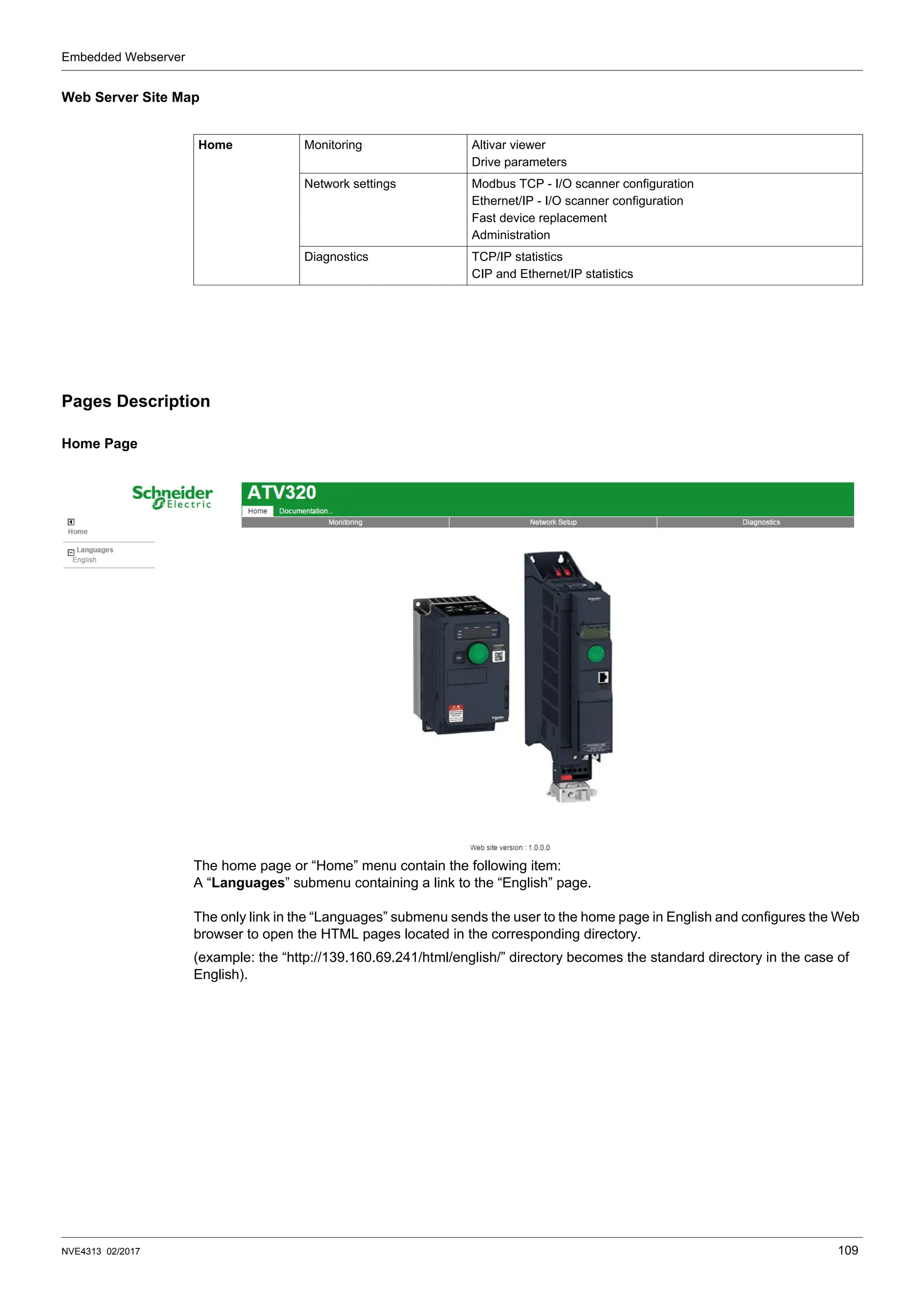
![Embedded Webserver
110 NVE4313 02/2017
Note About Java Applets
The Webserver downloads Java programs called “applets” to your computer. These applets communicate with
the drive using Modbus services (on port 502), thus establishing one or more connections between the
computer and the drive. Until an applet has been fully transmitted from the drive to the browser, a gray
rectangle appears in the place reserved for it in the page.
The applets associated with the Web pages monitor communication with the drive. When the drive no longer
responds to requests to update the data, the message “Link down” is displayed in one field and all the other
field contents are emptied.
Subsequently, the description of each page indicates the data refresh period requested by the applet loaded
on the computer. The refresh period actually observed depends on:
• The performance of the computer on which the Web browser is running,
• The communication system response time,
• The amount of data to be refreshed on the page.
Monitoring Menu
The “Monitoring” menu contains the two following items:
• A link to the “Altivar viewer” page:
The state indicated in the “Altivar State” field corresponds to the display on the drive integrated display
terminal. A delay may sometimes be noticed between the displays on the Web server and the display terminal,
depending on the performance of the computer used to display the pages using a Web browser and the
communication system performance.
The motor speed displayed on the “Motor Speed” gauge is calibrated according to the maximum frequency
[Max Frequency] (tFr) and the number of pairs of poles [Poles pair number] (PPn).
The LI… area gives the state of the drive terminals (logic inputs LI1 to LI16, logic outputs LO1, relay outputs
R1 to R2, analog inputs AI1 to AI3 and analog output AO1. When a logic input is active, the LED is green.
When a logic output is active, the LED is red.](https://image.slidesharecdn.com/atv320modbustcpethernetipmanualnve4131302-240821021710-4e33f5e9/75/ATV320_Modbus_TCP_EtherNet_IP_Manual_NVE41313_02-pdf-110-2048.jpg)
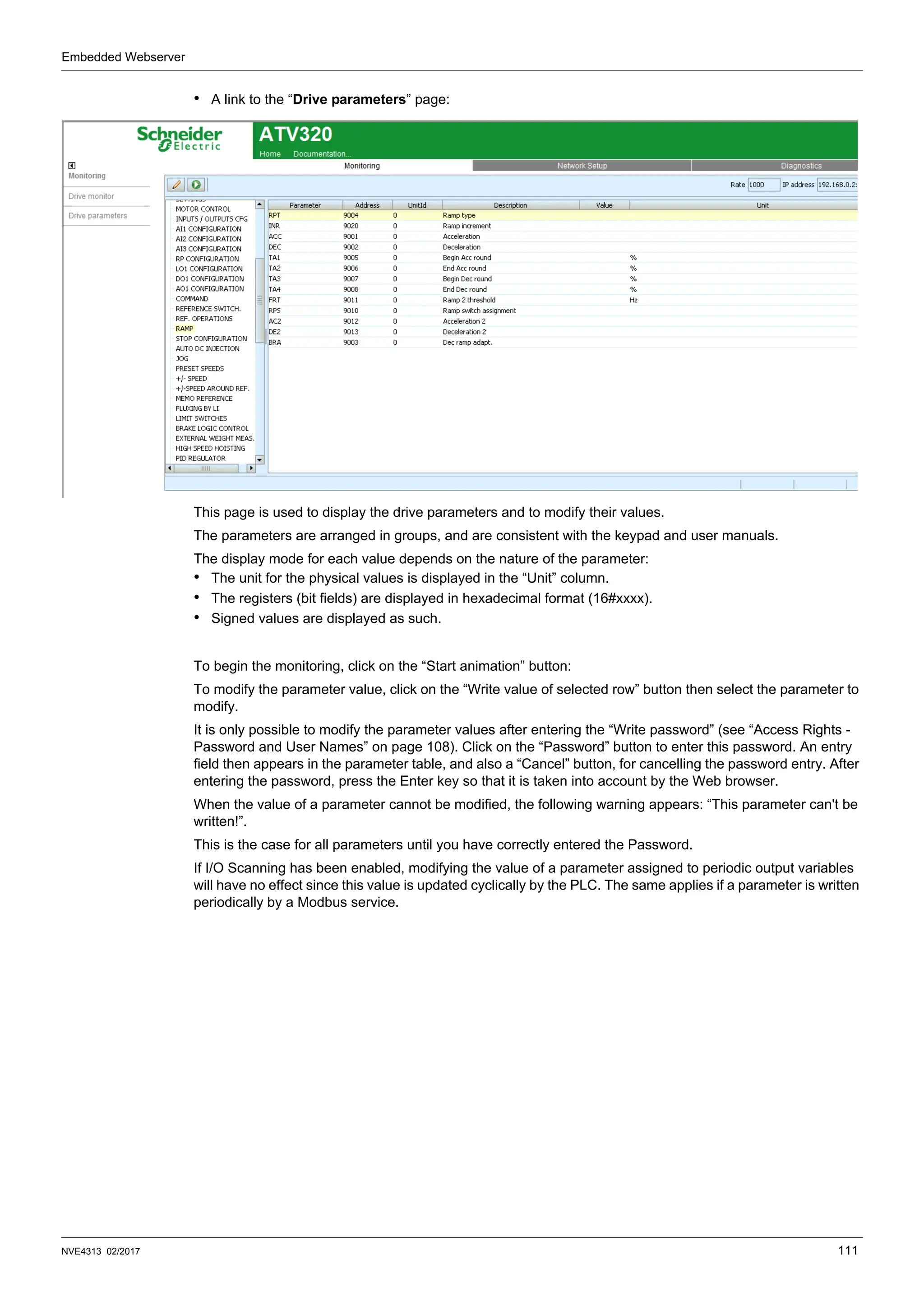
![Embedded Webserver
112 NVE4313 02/2017
Network Parameters
Modbus Scanner
This page is used to:
• Enable or disable I/O Scanning.
• Display and modify assignment of the I/O Scanning periodic variables.
• Set the communication monitoring time out.
All modifications are protected by the “Write password” modification password.
Click on the “PassWord” button to enter the”Write password”.
After correctly entering the password, you can access “I/O scanner”, “Time Out (s)”, “Master”, “Output
parameters”, “Input parameters” and the “Save” and “Abort” buttons.
By default, the password is “USER”. It can be modified in the “Data write password” page.
Enabling I/O Scanning
Control by the I/O scanner is enabled if the “I/O scanner” field is at the value “Yes” and is disabled by the value
“No”.The “I/O scanner” field corresponds to the parameter [Eth IO scan act] (IOSA).
NOTE: Disabling I/O Scanning results in loss of control if a PLC is using an I/O scanner.
Before disabling I/O Scanning, you must disable the time out (set the value to 0). However, communication
monitoring remains active and the card triggers a communication detected fault at the end of the period defined
by the time out. In factory settings mode, the drive then changes to [Fieldbus Com Interrupt] (CnF) error.
Once the value in the “I/O scanner” field has been modified, it may take a while to update the page, depending
on the capacity of your computer.
The “I/O scanner” field corresponds to the parameter [Eth IO scan act] (IOSA).
Assigning the I/O Scanning periodic variables](https://image.slidesharecdn.com/atv320modbustcpethernetipmanualnve4131302-240821021710-4e33f5e9/75/ATV320_Modbus_TCP_EtherNet_IP_Manual_NVE41313_02-pdf-112-2048.jpg)
![Embedded Webserver
NVE4313 02/2017 113
NOTE: Modifying the assignment of the periodic variables can result in loss of control if a PLC is using an I/O
scanner.
To modify the I/O Scanning periodic variables, proceed as follows:
• Enter “No” in the “I/O scanner” field.
• Modify the assignment of periodic variables.
• Apply these modifications using the “Save” button.
• Enter “Yes” in the “I/O scanner” field.
Once the value in the “I/O scanner” field has been set to “No”, it may take a while to update the page,
depending on the capacity of your computer. A dropdown menu is used to modify the assignment of each of
the periodic variables.
Click on the periodic variable whose assignment you wish to modify, then choose the code corresponding to
the drive parameter to be assigned. The parameter can be chosen from the drop down list or directly entered
with its Modbus address.
All modifications to “Output parameters” and/or “Input parameters” can be confirmed by clicking on the “Save”
button or canceled by clicking the “Abort” button.
Each time the “Save” button is pressed, the address table will be saved to an EEPROM on the Ethernet card.
The assignments are now saved, even if the power is turned off.
Master
To configure reservation, enter an IP address other than [0.0.0.0] in the “Master” field. This field is equivalent
to the [IP Master] (IPP-) parameter.
Time out
This page can also be used to modify the communication monitoring “time out”. All entries must be confirmed
by pressing “Enter”.
The accepted values are as follows:
• 0: No communication check.
• 0.5 to 60.0 s: Time out value.
See “Configuring Communication Detected Fault Management” on page 49. The default time out value is 2 s
(display: “2.0”).
The “Time Out” field corresponds to the [time out] (tOUt) parameter.](https://image.slidesharecdn.com/atv320modbustcpethernetipmanualnve4131302-240821021710-4e33f5e9/75/ATV320_Modbus_TCP_EtherNet_IP_Manual_NVE41313_02-pdf-113-2048.jpg)
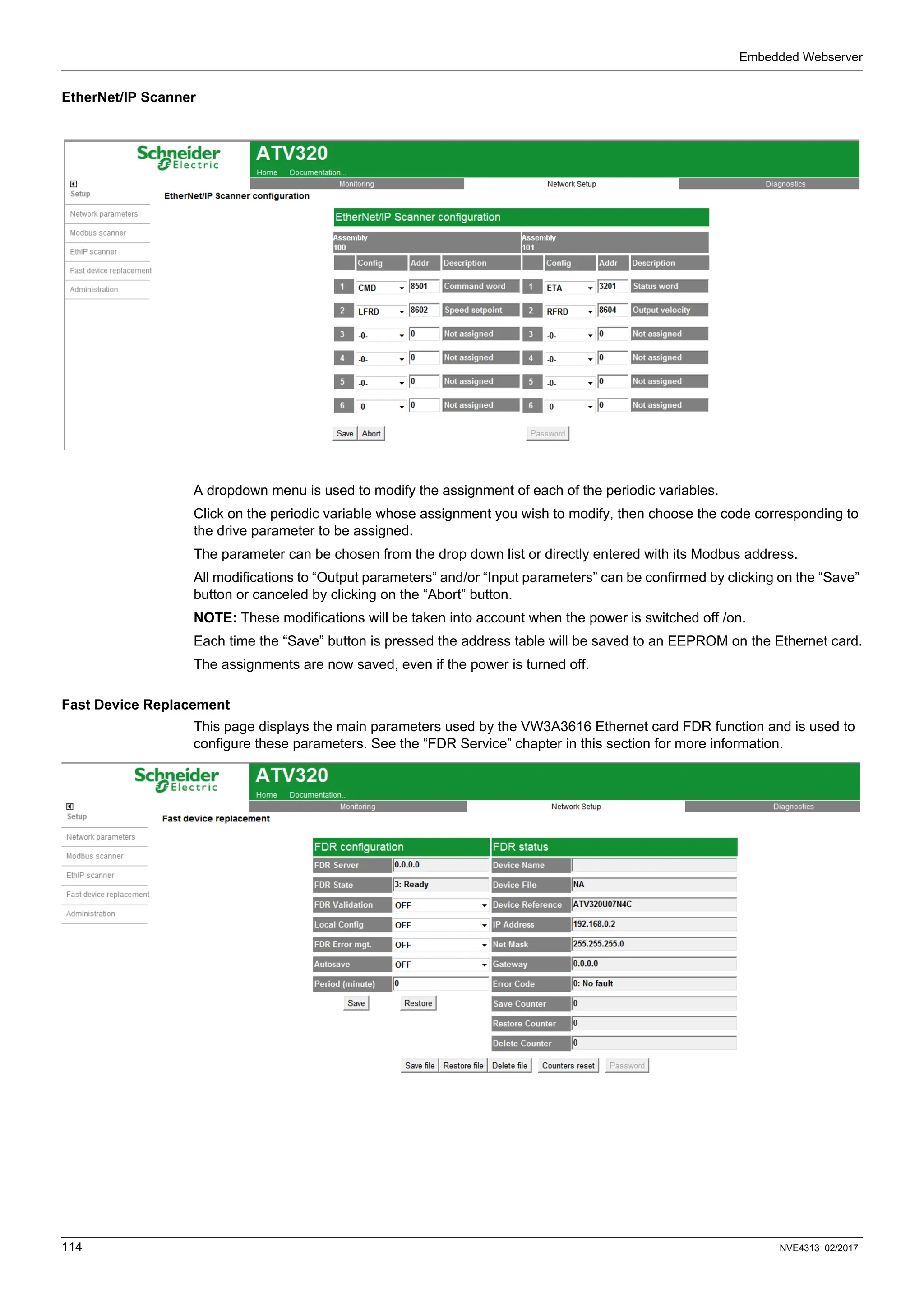
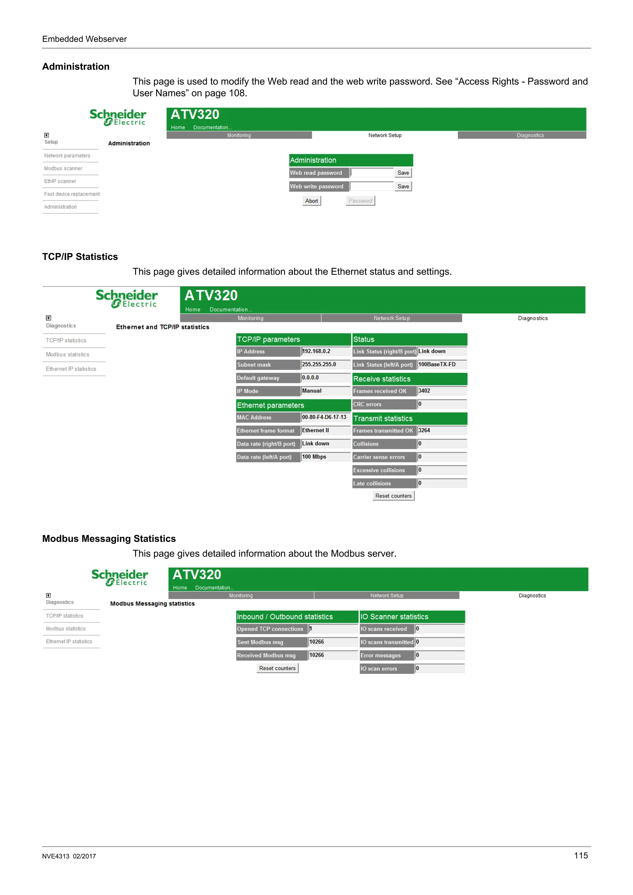
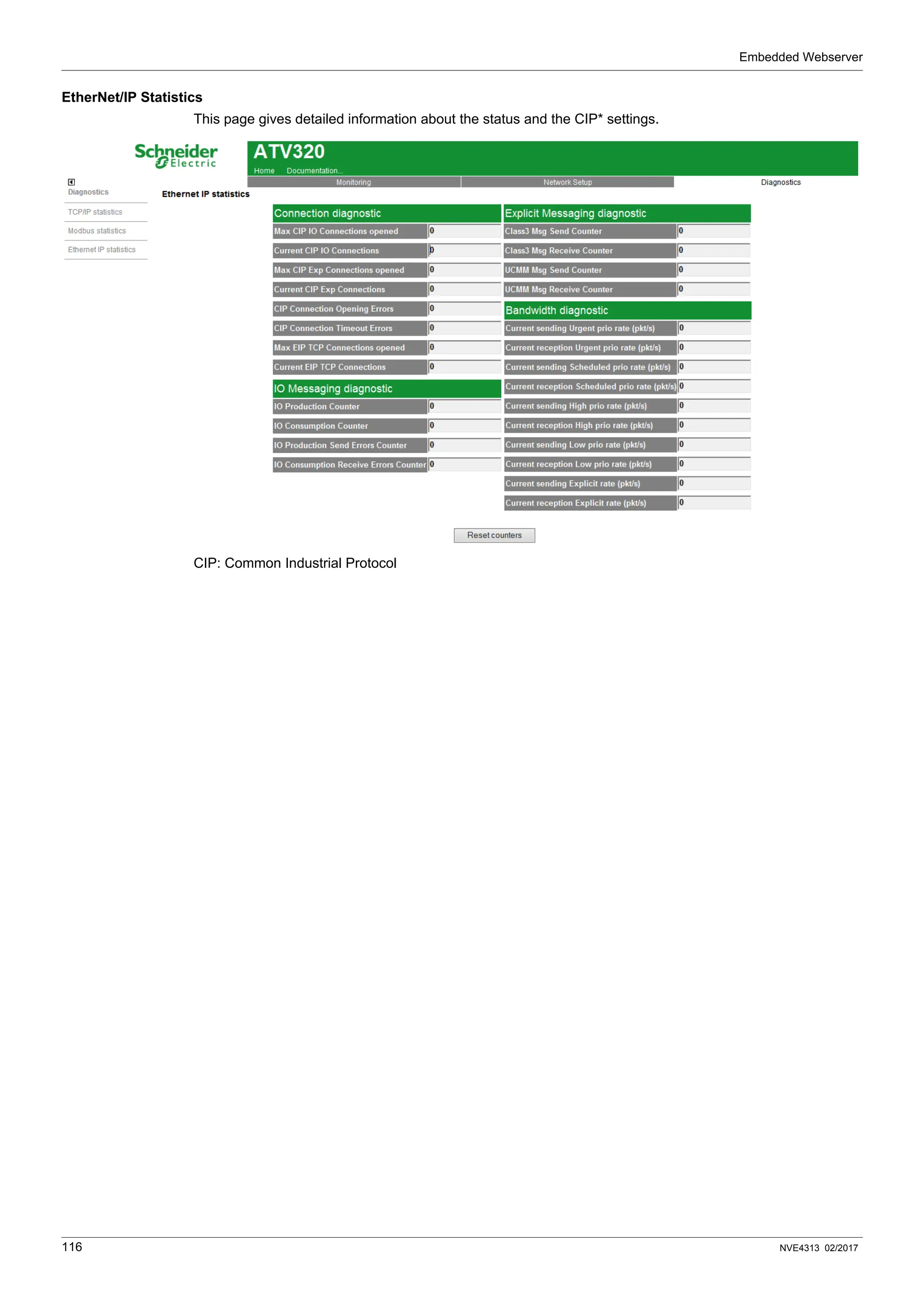
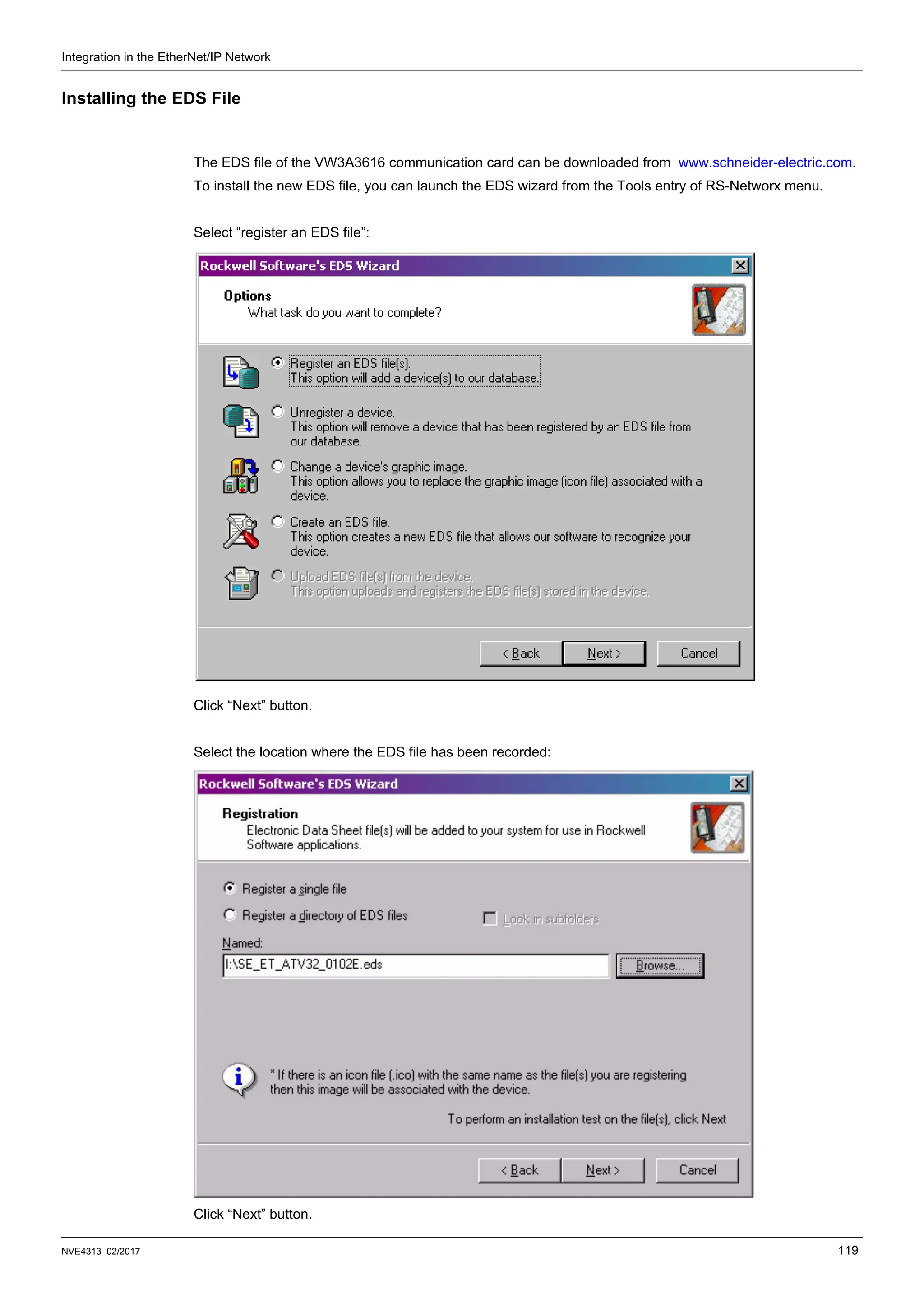
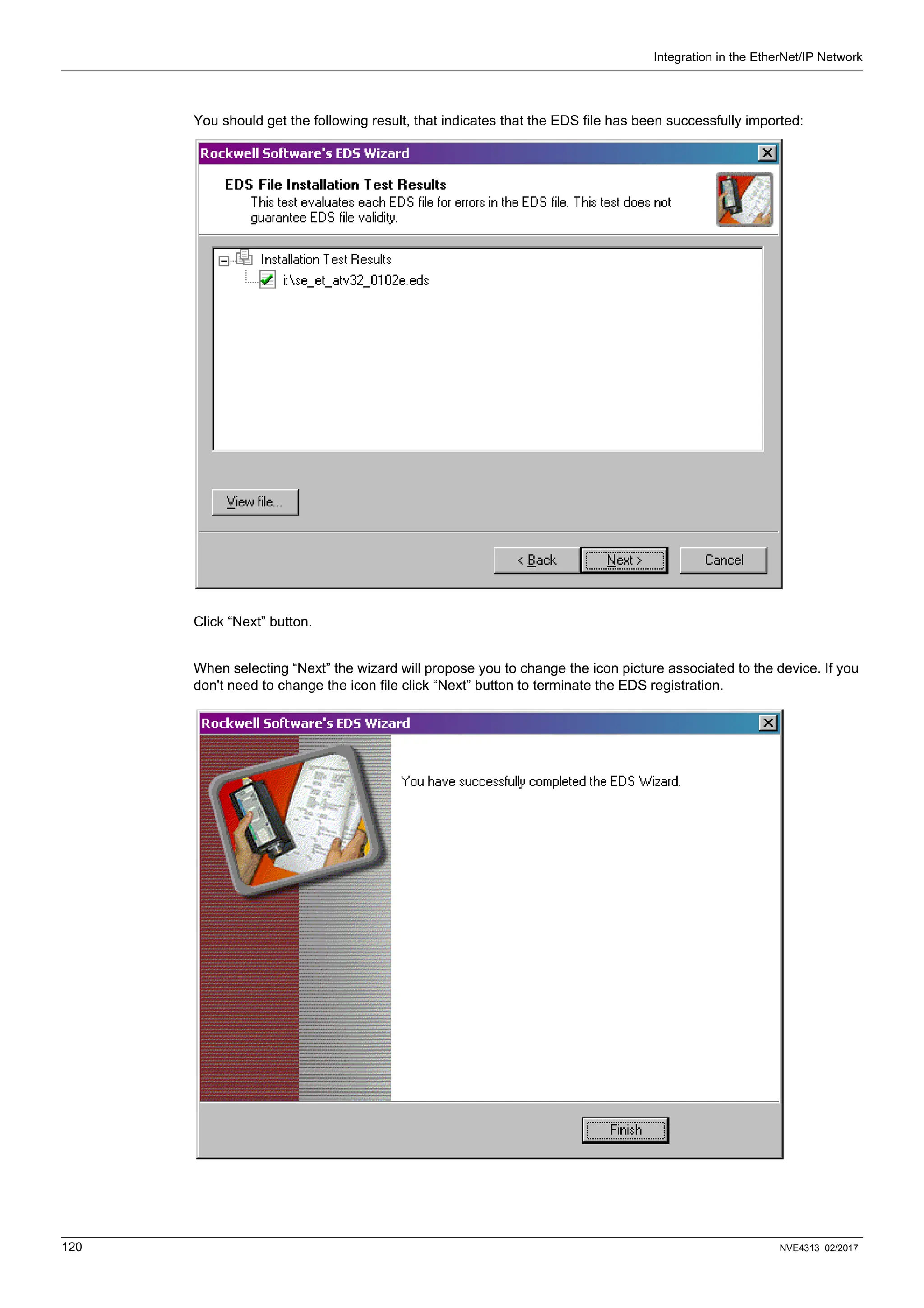
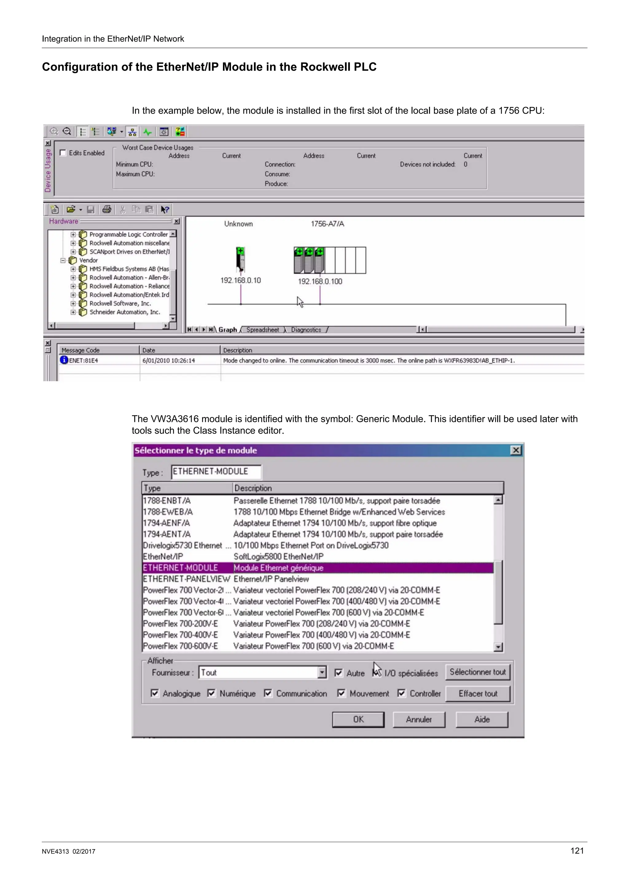
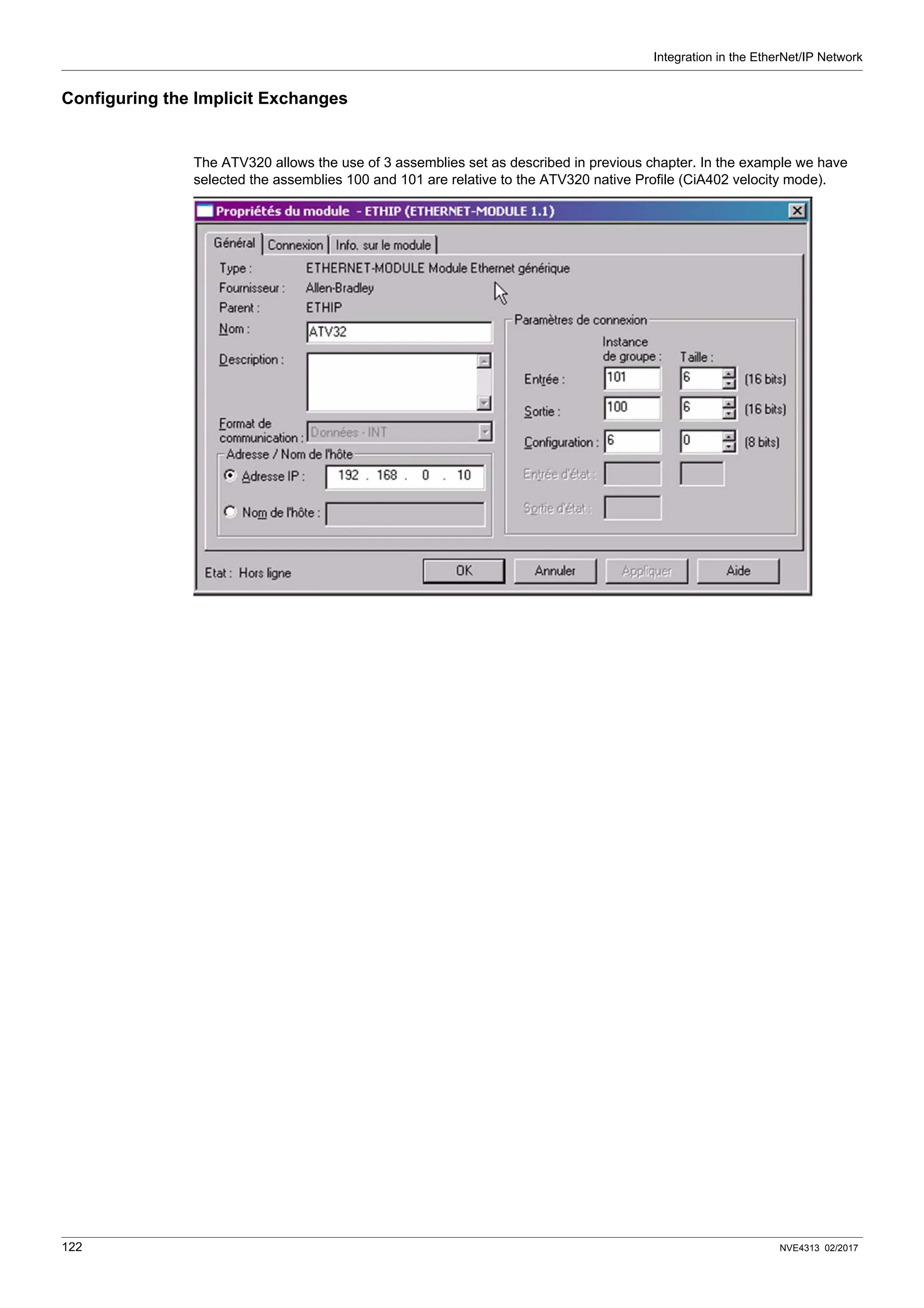
![Integration in the EtherNet/IP Network
NVE4313 02/2017 123
Once configured, the data objects are automatically updated and linked with the implicit exchanges
mechanism:
The assemblies are linked to the Option card communication scanner - see relative chapter - the example is
based on the default values of the communication scanner.
I/O PLC data ATV320 parameter Linked to: (Through Communication scanner)
Input ATV320:I.Data[0] (OMA1) (EtA)
ATV320:I.Data[1] (OMA2) (rFrd)
Output ATV320:O.Data[0] (OCA1) (CMd)
ATV320:O.Data[1] (OCA2) (LFrd)](https://image.slidesharecdn.com/atv320modbustcpethernetipmanualnve4131302-240821021710-4e33f5e9/75/ATV320_Modbus_TCP_EtherNet_IP_Manual_NVE41313_02-pdf-123-2048.jpg)
![Integration in the EtherNet/IP Network
124 NVE4313 02/2017
Configuration of the Communication Scanner
The communication scanner is accessible via the following menus: [Communication] (COM-) and
[Communication Module] (cbd) submenus.
The 6 output variables and the 6 input variables are assigned by means of parameters (OCA1) to (OCA6)
and (OMA1) to (OMA6). An (OCA x) or (OMA x) parameter with a value of zero is not linked to a
parameter in the drive.
These 6 parameters are described in the table below.
(OCA x) or (OMA x) defines the addresses.
[Scan.Out1 address] (OCA1) (CMd)
[Scan.Out2 address] (OCA2) (LFrd)
[Scan.Out3 address] (OCA3) 0
[Scan.Out4 address] (OCA4) 0
[Scan.Out5 address] (OCA5) 0
[Scan.Out6 address] (OCA6) 0
[Scan.IN1 address] (OMA1) (EtA)
[Scan.IN2 address] (OMA2) (rFrd)
[Scan.IN3 address] (OMA3) 0
[Scan.IN4 address] (OMA4) 0
[Scan.IN5 address] (OMA5) 0
[Scan.IN6 address] (OMA6) 0](https://image.slidesharecdn.com/atv320modbustcpethernetipmanualnve4131302-240821021710-4e33f5e9/75/ATV320_Modbus_TCP_EtherNet_IP_Manual_NVE41313_02-pdf-124-2048.jpg)
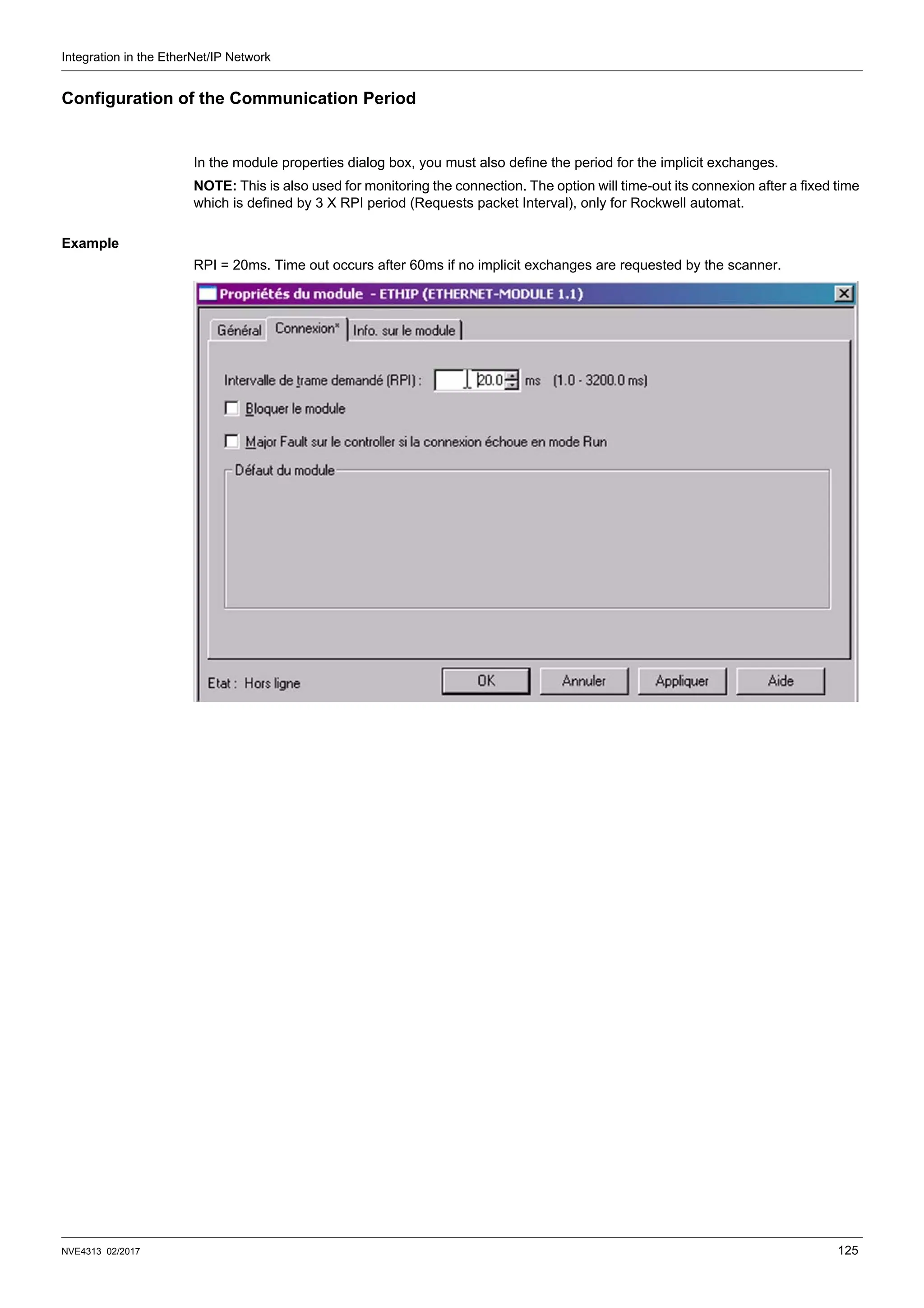
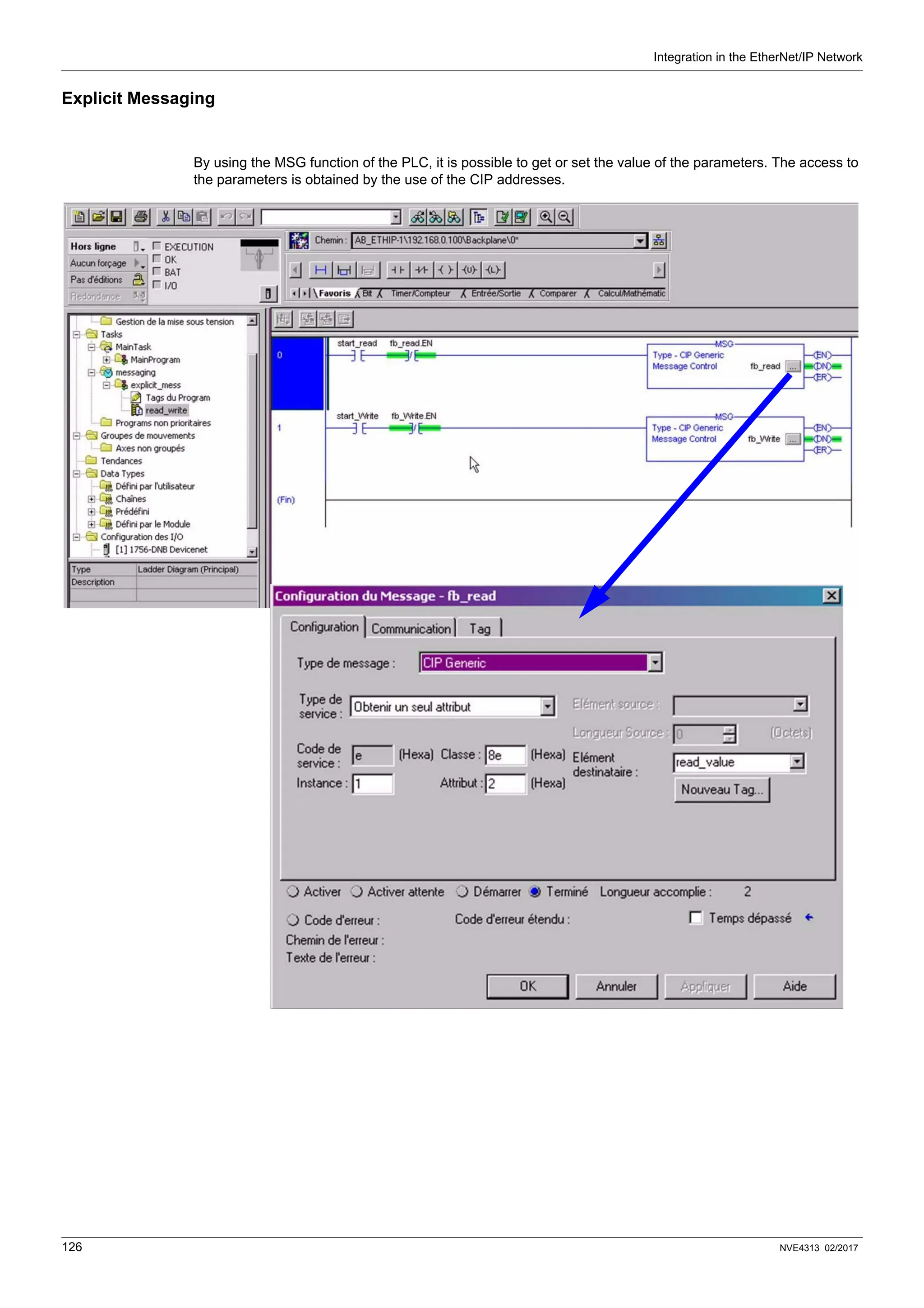
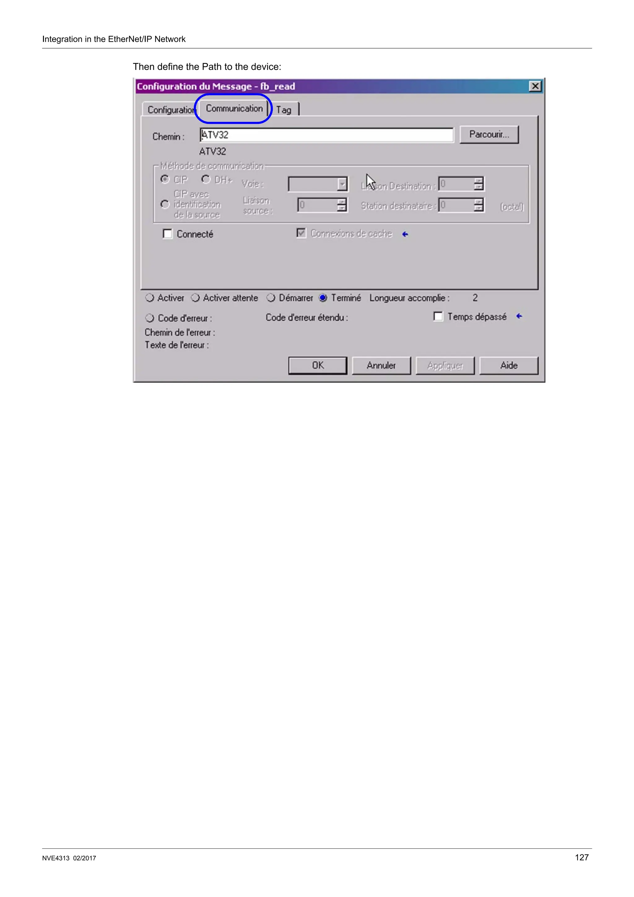
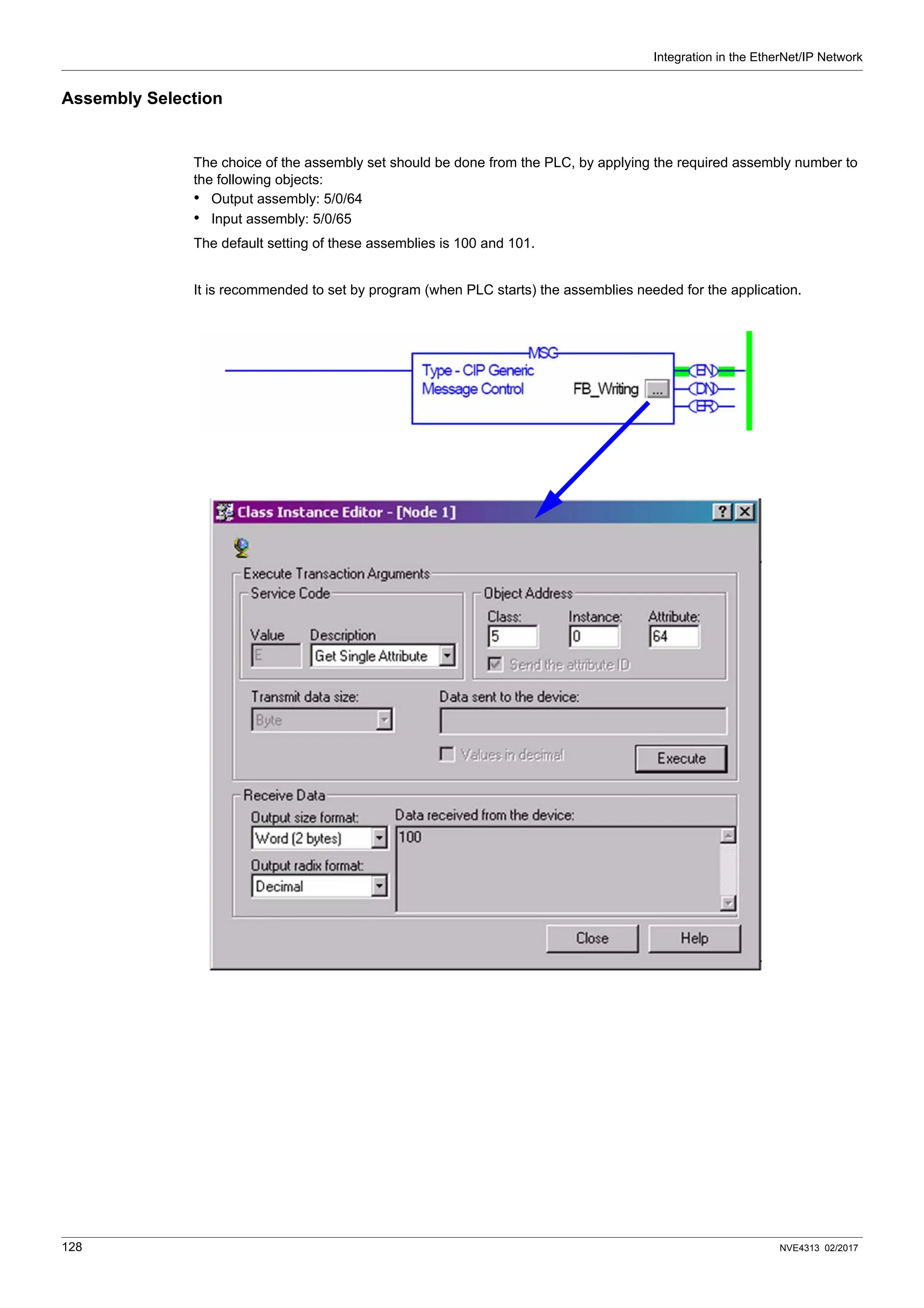
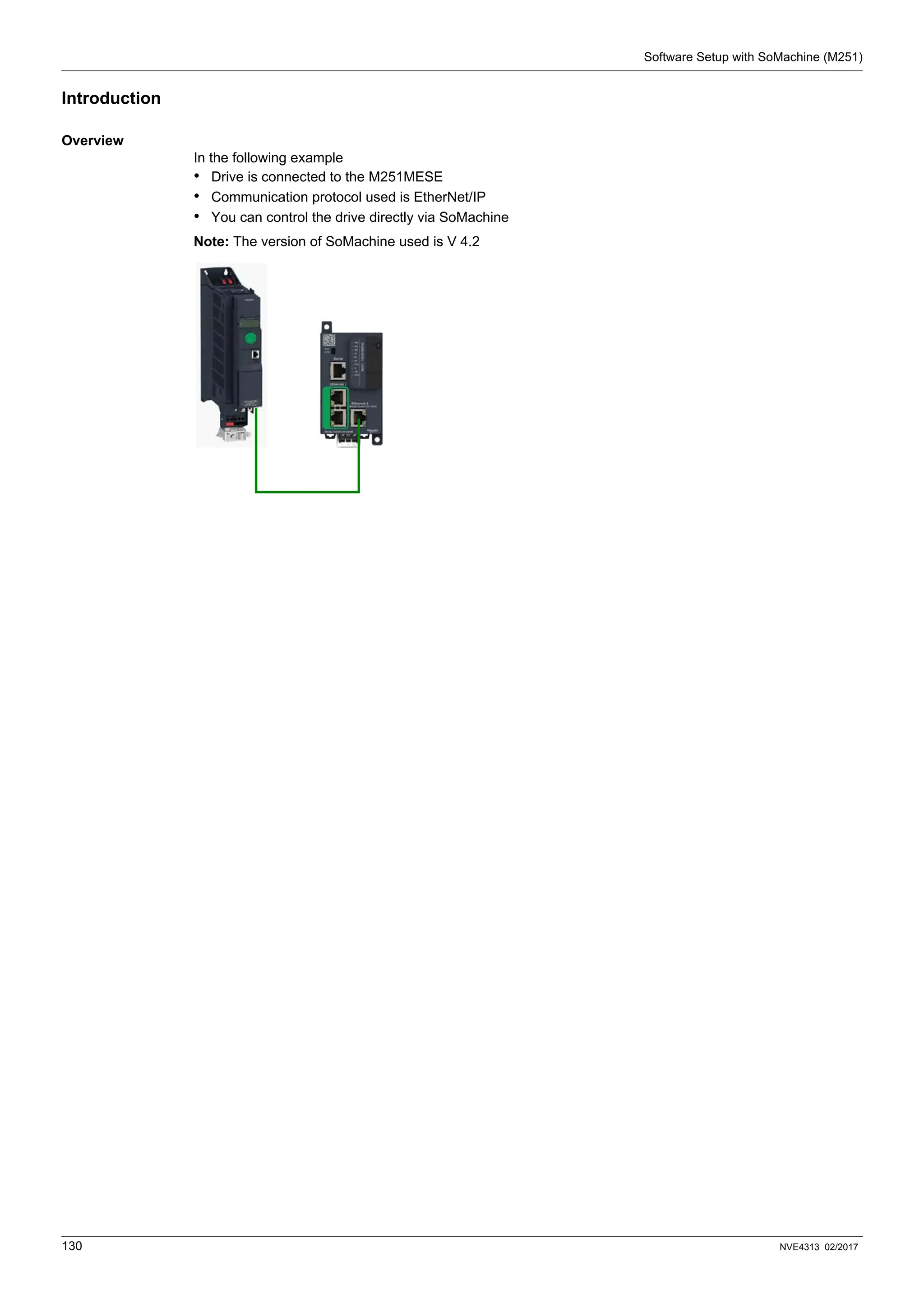
![Software Setup with SoMachine (M251)
NVE4313 02/2017 131
Drive Configuration
Overview
In the following example, the drive configuration must be done as follows in-order to establish communication
between the drive and the PLC.
You can configure the drive using the
• Graphical Display Terminal
• DTM via the SoMachine container
Factory Settings
Before configuring the drive, make sure that you reset the drive to factory settings
Go to
• [Drive menu] (DRI-) menu, [Configuration] (CONF-) submenu,
• [Factory settings] (FCS-) submenu
Then configure the following parameters
• [Parameters group list] (FrY-) to [All] (All)
• [Go to Factory Settings] (GFS) to OK
Command Configuration
To control the drive with an Ethernet master, select Ethernet as active command channel
Go to
• [Drive menu] (DRI-) menu, [Configuration] (CONF-) submenu,
• [Full] (Full-) menu
• [Command] (CTL-) menu
Then configure
• [Ref Freq 1 Config] (Fr1) parameter to [Ref. Freq-Com. Module] (NET) value
Communication Configuration
To set the Ethernet address of the drive, go to:
• [Communication] (COM-) menu
• [Communication module] (CBD-) submenu
Then configure
• [Ethernet protocol] (ETHM) to value [EthernetIP] (ETIP)
• [IP mode] (IPM) to value [Fixed] (MAnu)
• [IP Module] (IPC) to value 192.168.0.2
• [IP Mask] (IPM) to value 255.255.255.0
You must restart the device to take into account the modified Ethernet related parameters.](https://image.slidesharecdn.com/atv320modbustcpethernetipmanualnve4131302-240821021710-4e33f5e9/75/ATV320_Modbus_TCP_EtherNet_IP_Manual_NVE41313_02-pdf-131-2048.jpg)
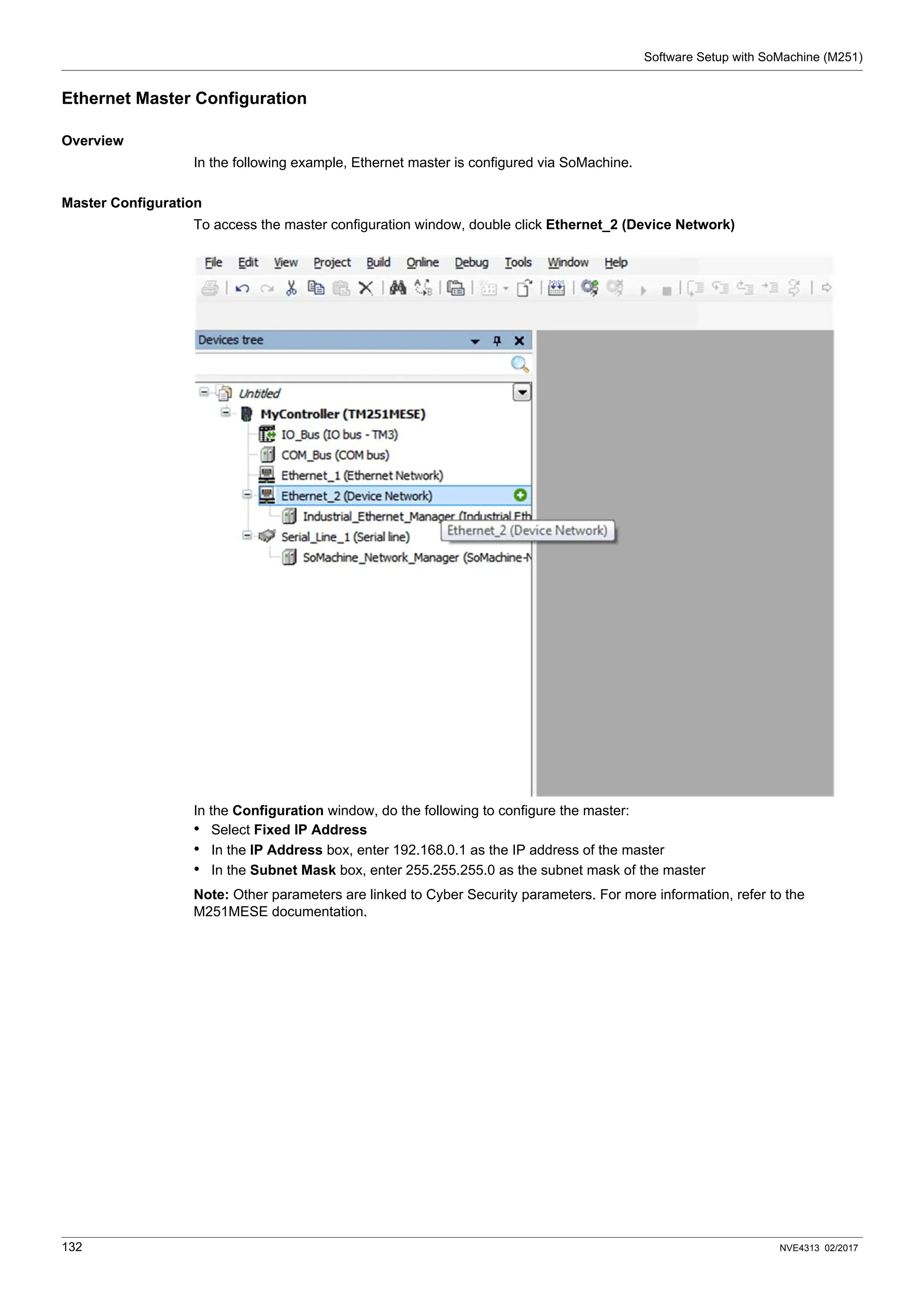
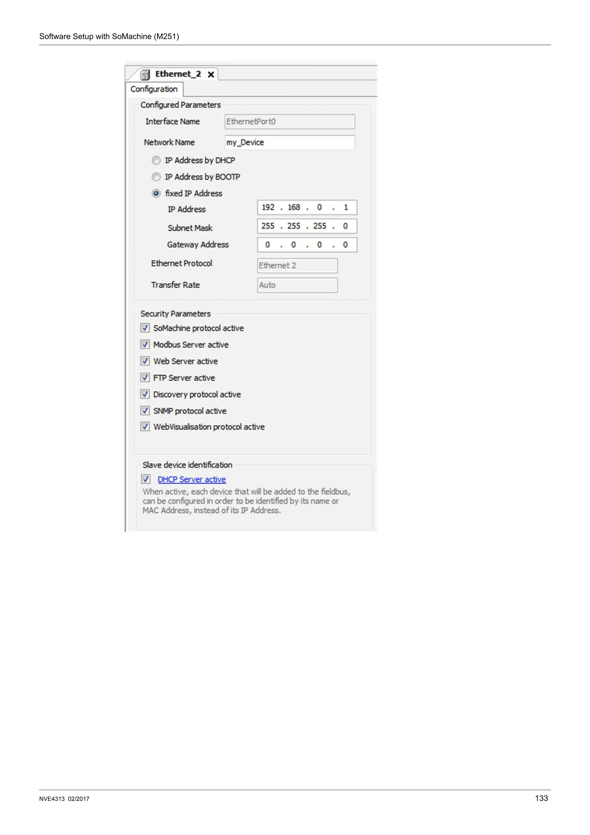
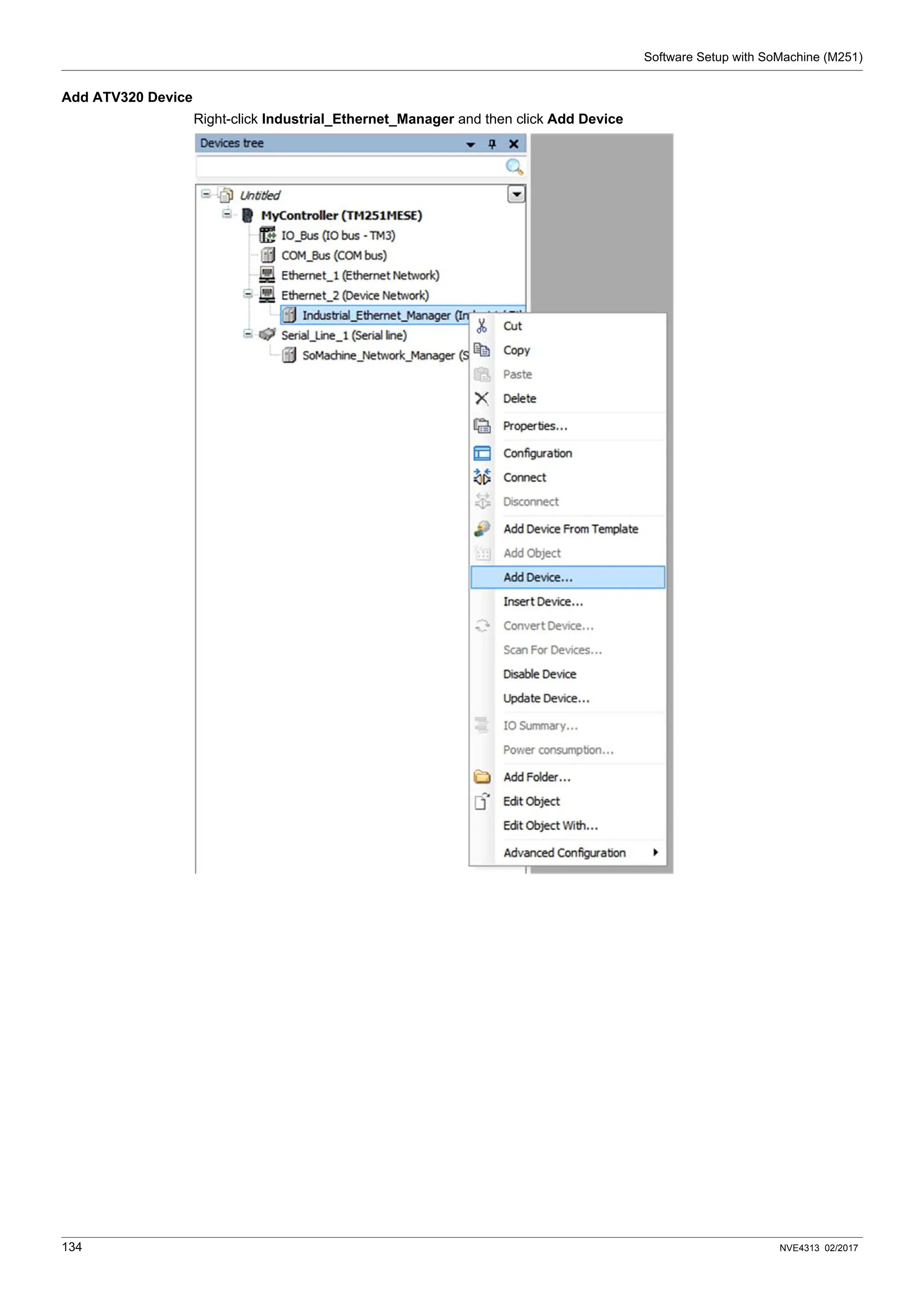
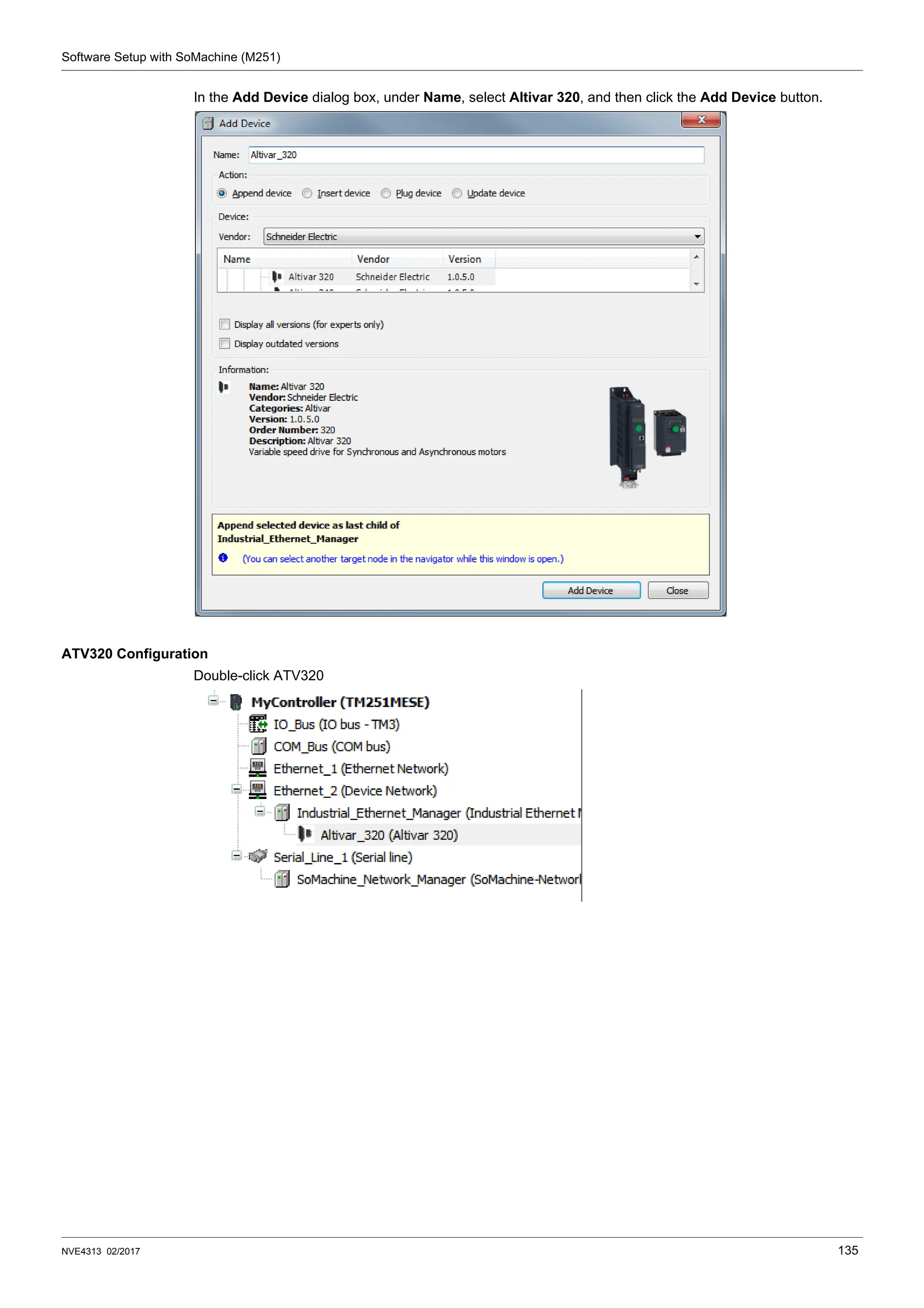

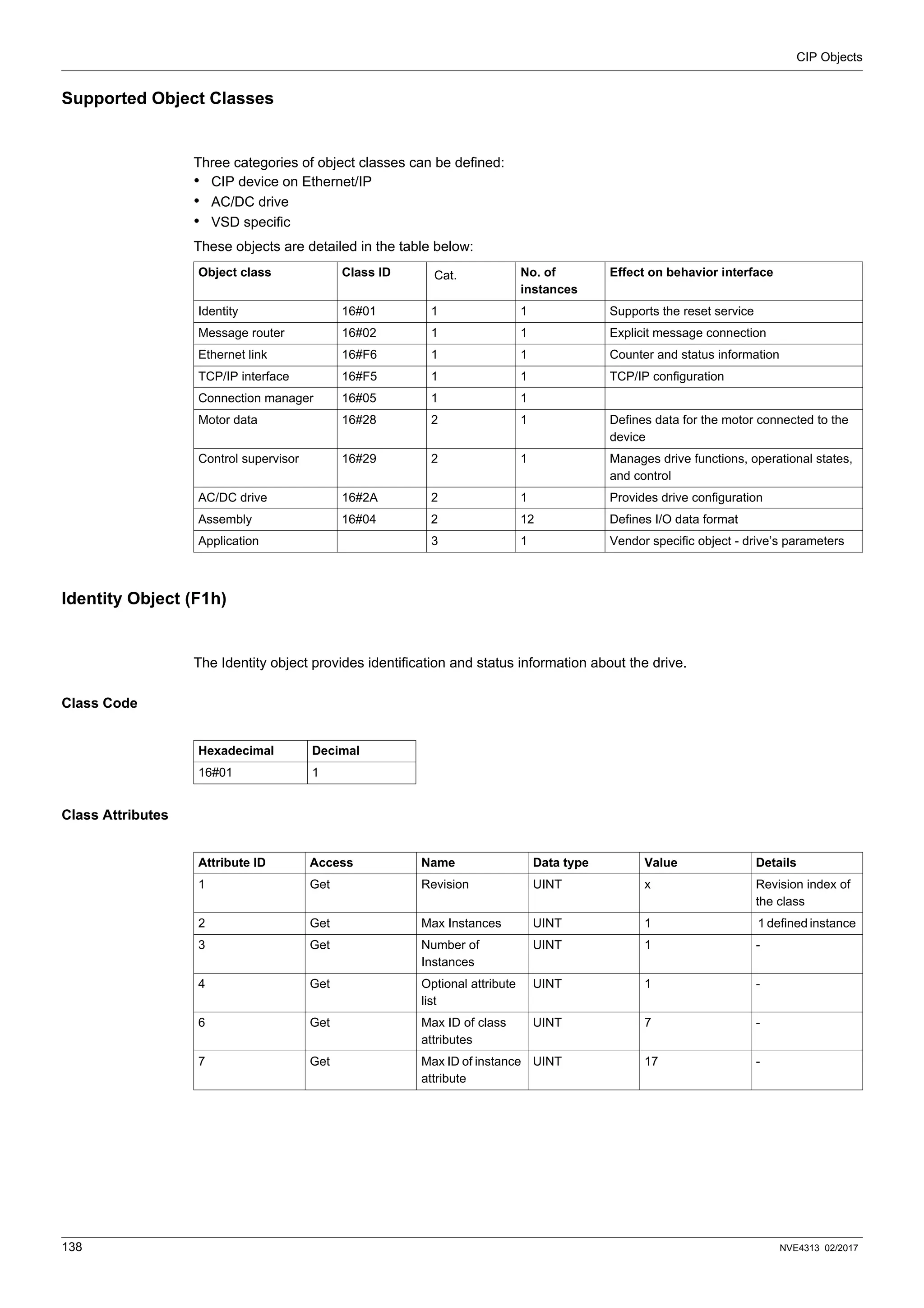
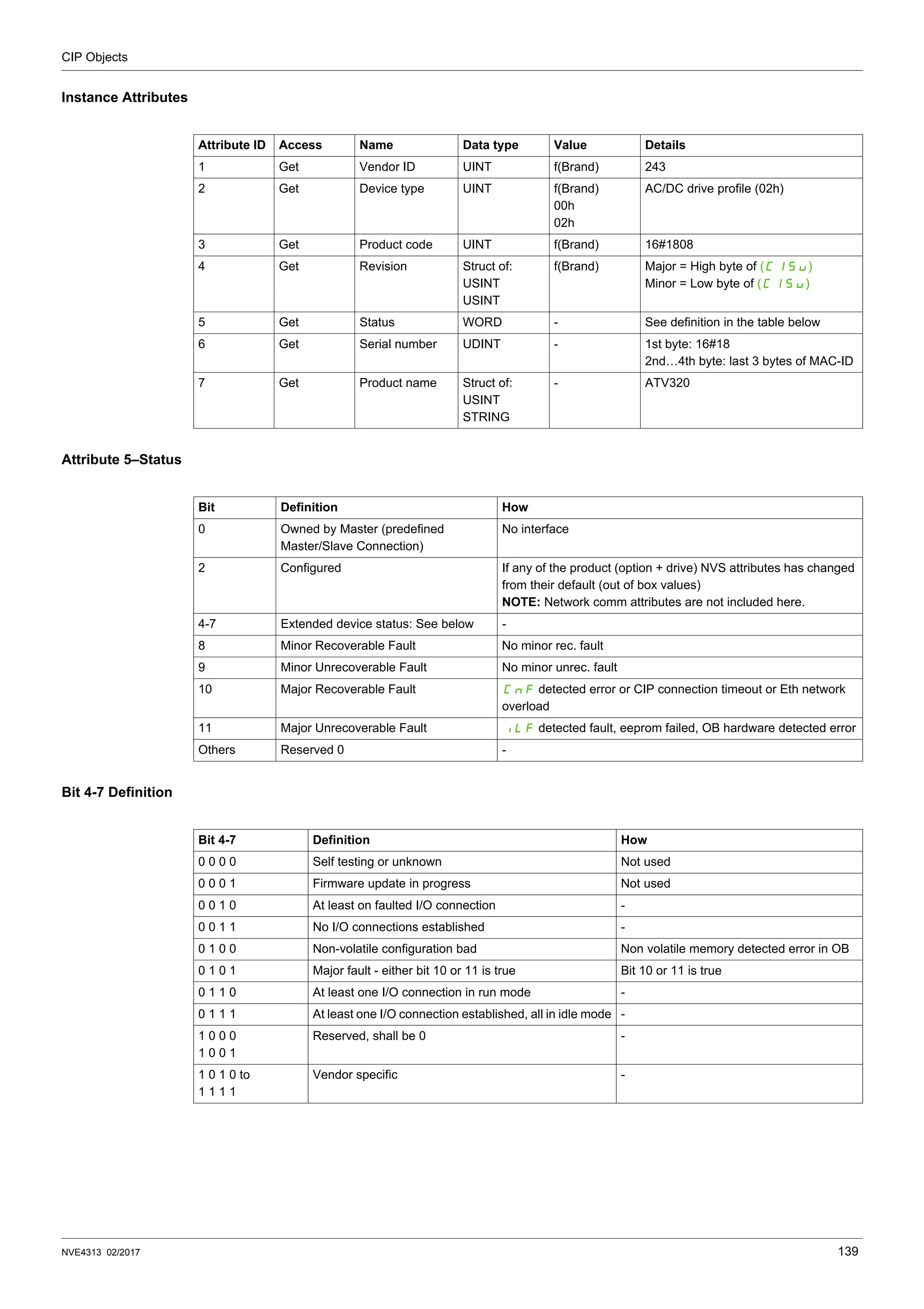
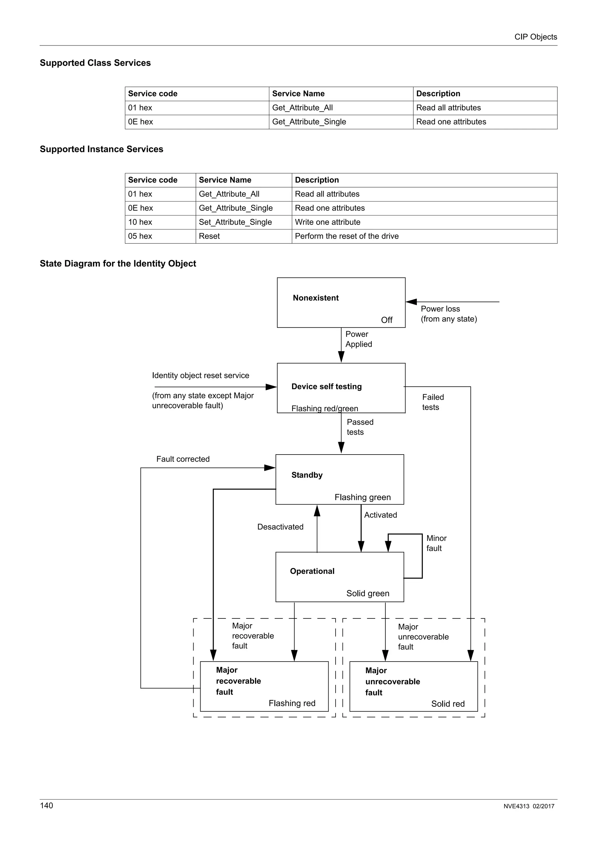
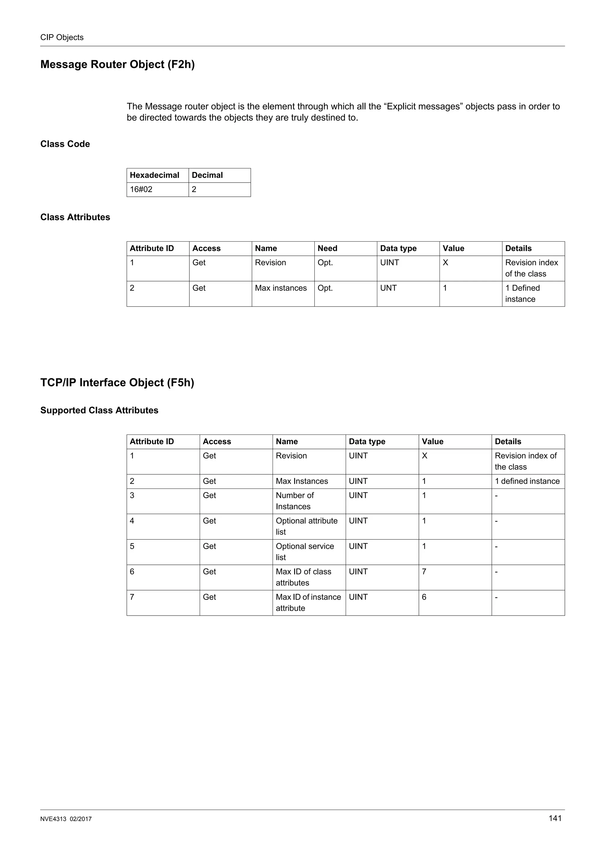
![CIP Objects
142 NVE4313 02/2017
Supported Instance Attributes
(1) If set option board parameter OBP:FDRU=0 will also be set to implicitly disable the FDR mechanism on the DHCP
protocol. This to be compatible with CIP tools that has configured the device to operate in a non-FDR specific
environment. The user has to manually enable the feature if desired to be used.
Attribute
ID
Access Name Data type Details
1 Get Status DWORD 0 = The Interface Configuration attribute has not been
configured
1 = The Interface Configuration attribute contains valid
configuration
2 Get Configuration
capability
DWORD Bit 0 = 1 (TRUE) shall indicate the device is capable of
obtaining its network configuration via BOOTP
Bit 1 = 1 (TRUE) shall indicate the device is capable of
resolving host names by querying a DNS server
Bit 2 = 1 (TRUE) shall indicate the device is capable of
obtaining its network configuration via DHCP
Bit 3 = 1 (TRUE) shall indicate the device is capable of
sending its host name in the DHCP request
Bit 4 = 1 (TRUE) shall indicate the Interface Configuration
attribute is setable.
Bit 5-31: reserved
3 Get/Set Configuration
control
DWORD Bits 0-3 Start-up configuration
0 = The device shall use the interface configuration values
previously stored
1 = The device shall obtain its interface configuration values
via BOOTP
2 = The device shall obtain its interface configuration values
via DHCP upon start-up (1)
3-15 = Reserved for future use
Bit 4 = 1 (TRUE), the device shall resolve host names by
querying a DNS server
Bit 5-31: reserved
4 Get Physical Link Object STRUCT of
UINT
EPATH
Path Size
Path: Logical segments identifying the physical link object
Example [20][F6][24][01]: [20] = 8 bit class segment type;
[F6] = Ethernet Link Object class; [24] = 8 bit instance
segment type; [01] = instance 1
5 Get/Set Interface
Configuration
STRUCT of
UDINT
UDINT
UDINT
UDINT
UDINT
String
IP address (0: no address configured)
Network Mask (0: no Network mask configured)
Gateway address (0: no address configured)
Name server address (0: no address configured)
Name server address 2 (0: no address configured)
Domain Name
6 Get/Set Host Name String Read/write name of the drive
8 Get/Set TTL value USINT TTL value for Ethernet/IP multicast packets
9 Get/Set Mcast Config Struct Of. IP Multicast address configuration
Alloc Control USINT 0 - Use default allocation algorithm to generate multicast
addresses
1 - Multicast addresses shall be allocated according to the
values in Num Mcast and Mcast Start Addr
Reserved USINT Shall be 0
Num Mcast UINT Number of multicast addresses to allocate for EtherNet/IP
Mcast Start Addr UDINT Starting multicast address from which to begin allocation](https://image.slidesharecdn.com/atv320modbustcpethernetipmanualnve4131302-240821021710-4e33f5e9/75/ATV320_Modbus_TCP_EtherNet_IP_Manual_NVE41313_02-pdf-142-2048.jpg)
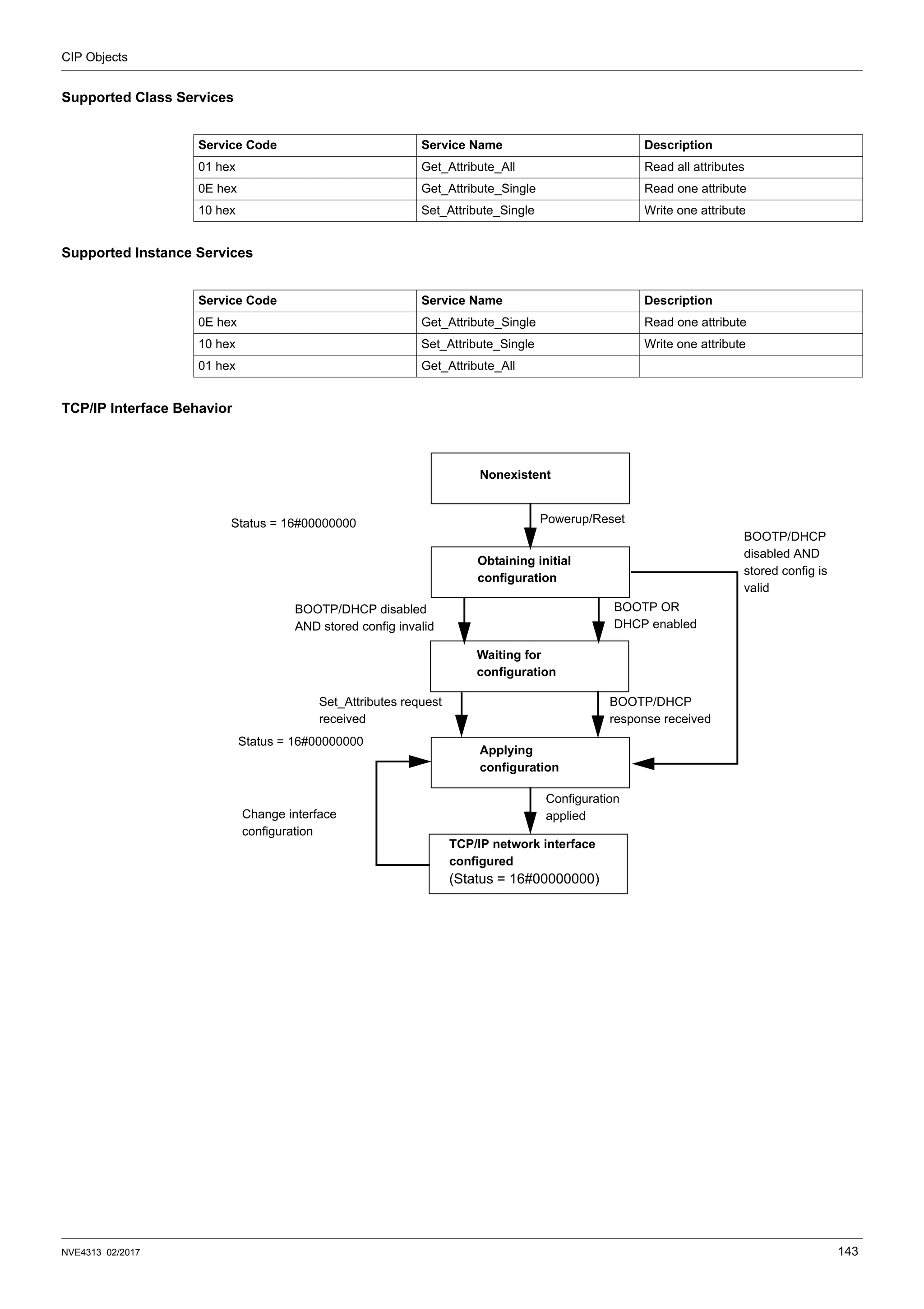
![CIP Objects
144 NVE4313 02/2017
Ethernet Link Object (F6h)
Supported Class Attributes
Supported Instance Attributes
Supported Class Services
Attribute ID Access Name Data type Value Details
1 Get Revision UINT X Revision index of
the class
2 Get Max Instances UINT 1 1 defined instance
3 Get Number of Instances UINT 1 -
6 Get Max ID of class attributes UINT 7 -
7 Get Max ID of instance attribute UINT 6 -
Attribute
ID
Access Name Data type Details
1 Get Interface Speed UDINT Interface speed currently in use
2 Get Interface Flags DWORD Bit 0: Link Status Indicates whether or not the Ethernet
802.3 communications interface is connected to an
active network. 0 indicates an inactive link; 1 indicates an
active link
Bit 1: Half/Full Duplex Indicates the duplex mode
currently in use. 0 indicates the interface is running half
duplex; 1 indicates full duplex
Bit 2-4: Negotiation Status
- 0 = Auto-negotiation in progress
- 1 = Auto-negotiation and speed detection failed
- 2 = Auto negotiation failed but detected speed
Duplex was defaulted
- 3 = Successfully negotiated speed and duplex
- 4 = Auto-negotiation not attempted. Forced speed
and duplex
Bit 5: Manual Setting Requires Reset. 0 indicates the
interface can activate changes to link parameters (auto-
negotiate, duplex mode, interface speed) automatically.
1 indicates the device requires a Reset service be issued
to its Identity Object in order for the changes to take
effect.
Bit 6: Local Hardware Fault. 0 indicates the interface
detects no local hardware fault; 1 indicates a local
hardware fault is detected. The meaning of this is
product-specific
Bit 7-31: Reserved Shall be set to zero
3 Get Physical Address USINT [6] MAC layer address
4 Get Interface counters - -
5 Get Media counters - -
6 Get/Set Interface Control - Force auto negotiate, half full and speed
7 Get Interface Type USINT 2
10 Get Interface Label SHORT_STRING ATV320: Instance 1: “Left”
ATV320: Instance 2: “Right”
Service code Service Name Description
0E hex Get_Attribute_Single Read one attribute
01 hex Get_Attribute_All -](https://image.slidesharecdn.com/atv320modbustcpethernetipmanualnve4131302-240821021710-4e33f5e9/75/ATV320_Modbus_TCP_EtherNet_IP_Manual_NVE41313_02-pdf-144-2048.jpg)