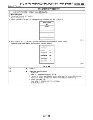
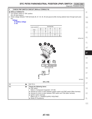
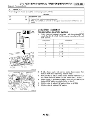
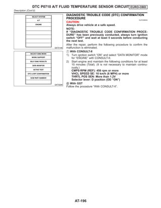
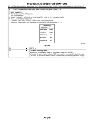
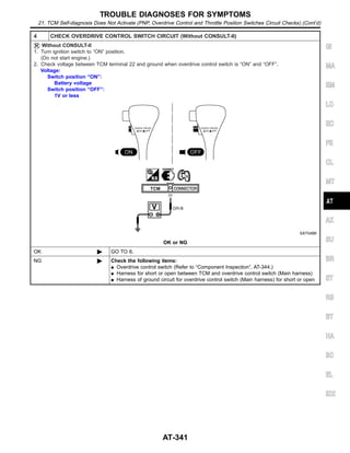
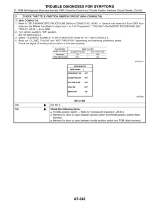
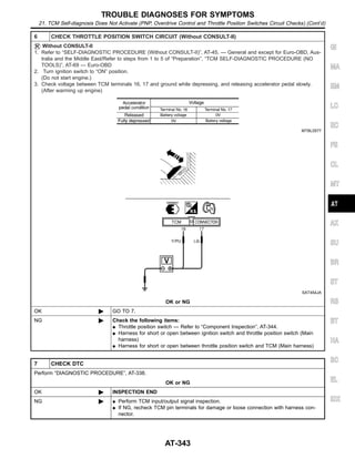
Download to read offline
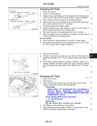
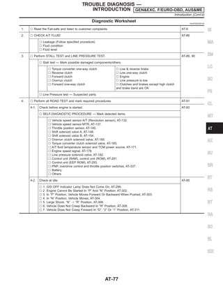
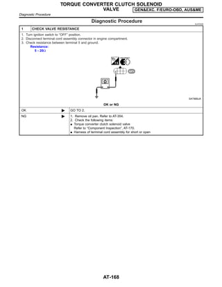
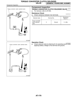
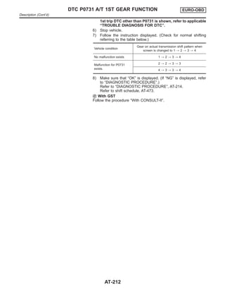
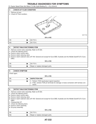
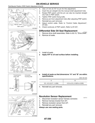
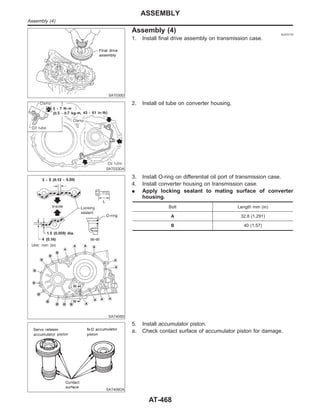
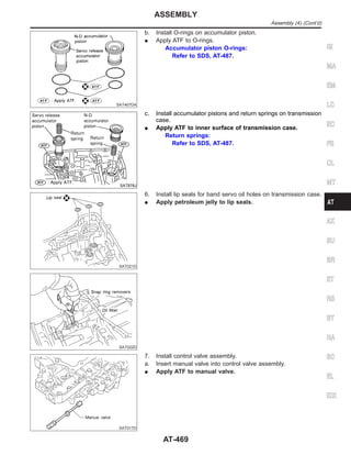
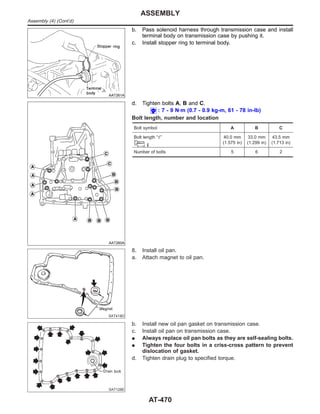
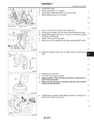
![parts. Apply petroleum jelly to protect O-rings and seals, or
hold bearings and washers in place during assembly. Do not
use grease.
I Extreme care should be taken to avoid damage to O-rings,
seals and gaskets when assembling.
I After overhaul, refill the transaxle with new ATF.
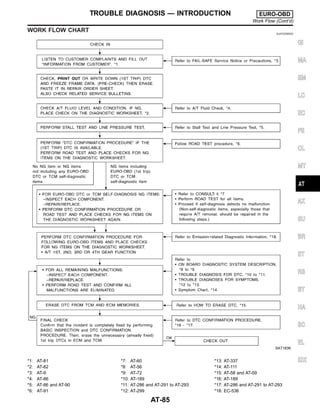
I When the A/T drain plug is removed, only some of the fluid is
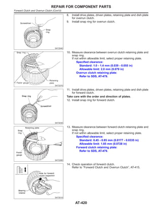
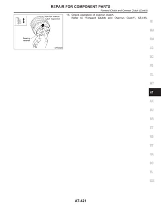
drained. Old A/T fluid will remain in torque converter and ATF
cooling system.
Always follow the procedures under “Changing A/T Fluid” in the
AT section when changing A/T fluid. Refer to “Changing A/T
Fluid”, AT-15.
Service Notice or Precautions NJAT0247
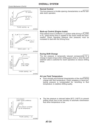
FAIL-SAFE NJAT0247S01
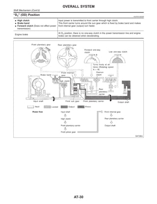
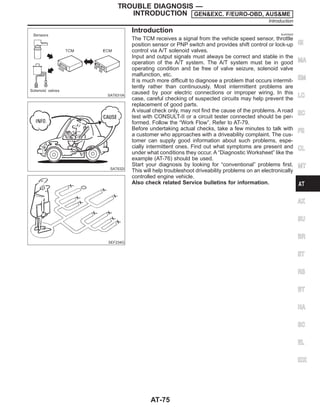
The TCM has an electronic Fail-Safe (limp home mode). This allows the vehicle to be driven even if a major
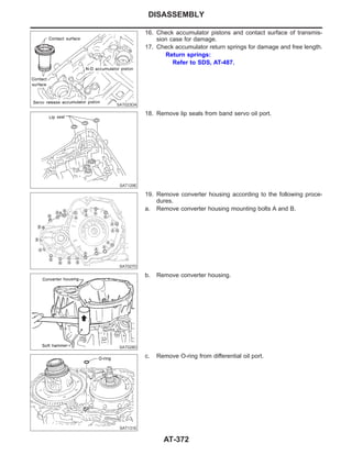
electrical input/output device circuit is damaged.
Under Fail-Safe, the vehicle always runs in third gear, even with a shift lever position of “1”, “2” or “D”. The
customer may complain of sluggish or poor acceleration.
When the ignition key is turned “ON” following Fail-Safe operation, O/D OFF indicator lamp blinks for about
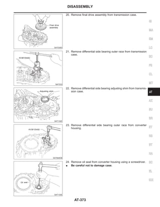
8 seconds. [For GENERAL AND EXCEPT FOR EURO-OBD, AUSTRALIA AND THE MIDDLE EAST; “SELF-
DIAGNOSTIC PROCEDURE (WITHOUT CONSULT-II)”, refer to AT-45 and for EURO-OBD; “TCM SELF-DI-
AGNOSTIC PROCEDURE (No Tools)”, refer to AT-69.]
The blinking of the O/D OFF or A/T check indicator lamp for about 8 seconds will appear only once and be
cleared. The customer may resume normal driving conditions.
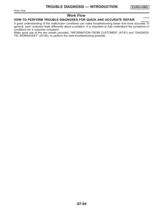
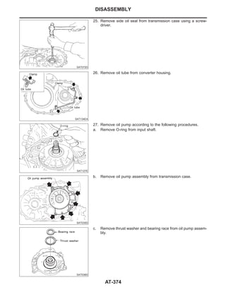
Always follow the “WORK FLOW” [Refer to AT-79 (General and except for Euro-OBD, Australia and the Middle
East), AT-84 (EURO-OBD).]
The SELF-DIAGNOSIS results will be as follows:
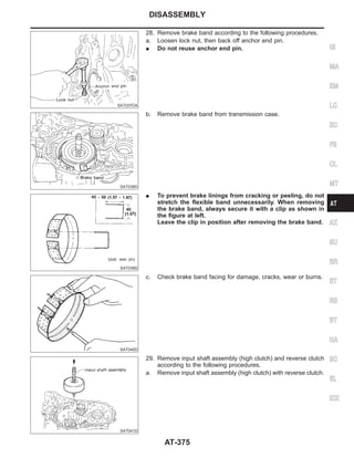
The first SELF-DIAGNOSIS will indicate damage to the vehicle speed sensor or the revolution sensor.
During the next SELF-DIAGNOSIS, performed after checking the sensor, no damages will be indicated.
TORQUE CONVERTER SERVICE NJAT0247S02
The torque converter should be replaced under any of the following conditions:
I External leaks in the hub weld area.
I Converter hub is scored or damaged.
I Converter pilot is broken, damaged or fits poorly into crankshaft.
I Steel particles are found after flushing the cooler and cooler lines.
I Pump is damaged or steel particles are found in the converter.
I Vehicle has TCC shudder and/or no TCC apply. Replace only after all hydraulic and electrical diagnoses
have been made. (Converter clutch material may be glazed.)
I Converter is contaminated with engine coolant containing antifreeze.
I Internal failure of stator roller clutch.
I Heavy clutch debris due to overheating (blue converter).
I Steel particles or clutch lining material found in fluid filter or on magnet when no internal parts in unit are
worn or damaged — indicates that lining material came from converter.
The torque converter should not be replaced if:
GI
MA
EM
LC
EC
FE
CL
MT
AX
SU
BR
ST
RS
BT
HA
SC
EL
IDX
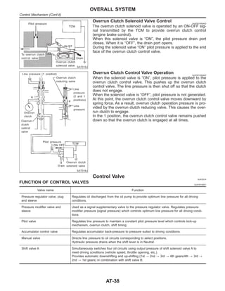
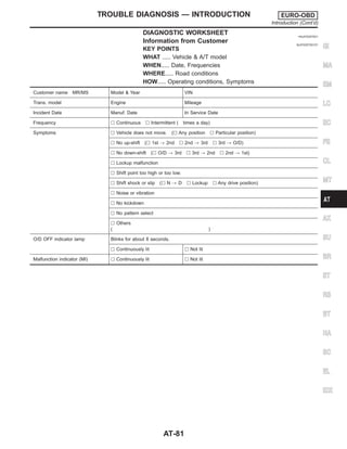
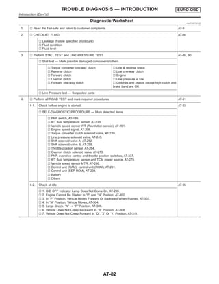
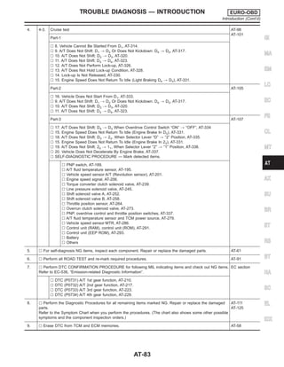
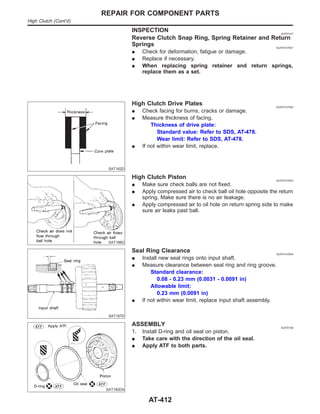
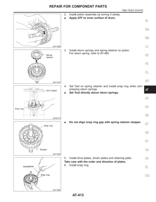
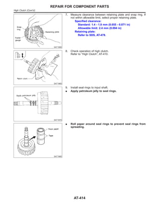
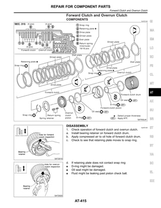
PRECAUTIONS
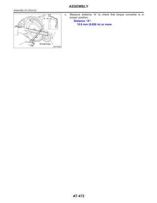
Precautions (Cont’d)
AT-9](https://image.slidesharecdn.com/at-230609060207-eaf4eb52/85/at-pdf-9-320.jpg)
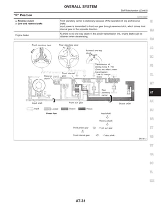
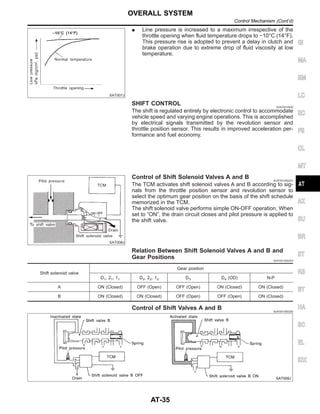
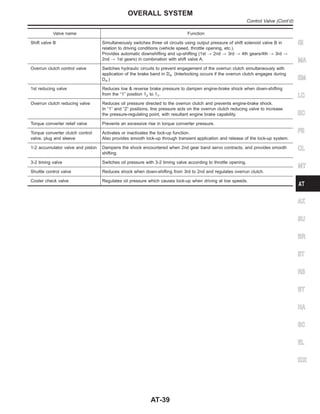
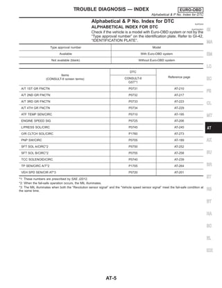
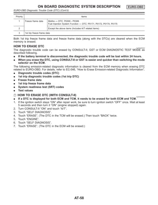
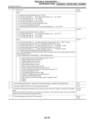
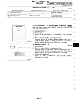
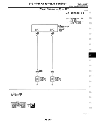
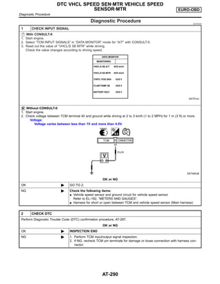
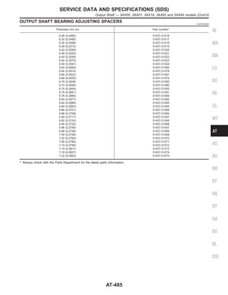
![SELF-DIAGNOSTIC RESULT TEST MODE NJAT0022S03
Detected items
(Screen terms for CONSULT-II, “SELF-DIAG
RESULTS” test mode) Malfunction is detected when ... Remarks
Item Display
No failure
(NO SELF DIAGNOSTIC FAILURE INDICATED
FURTHER TESTING MAY BE REQUIRED**)
I No failure has been detected.
Initial start I This is not a malfunction message (Whenever shut-
ting off a power supply to the TCM, this message
appears on the screen.)
INITIAL START —
Revolution sensor VHCL SPEED
SEN·A/T
I TCM does not receive the proper voltage signal from
the sensor.
Vehicle speed sensor
(Meter)
VHCL SPEED
SEN·MTR
I TCM does not receive the proper voltage signal from
the sensor.
Throttle position sen-
sor
Throttle position switch
THROTTLE POSI
SEN
I TCM receives an excessively low or high voltage
from the sensor.
Shift solenoid valve A SHIFT SOLENOID/V A I TCM detects an improper voltage drop when it tries
to operate the solenoid valve.
Shift solenoid valve B SHIFT SOLENOID/V B I TCM detects an improper voltage drop when it tries
to operate the solenoid valve.
Overrun clutch sole-
noid valve
OVERRUN CLUTCH
S/V
I TCM detects an improper voltage drop when it tries
to operate the solenoid valve.
T/C clutch solenoid
valve
T/C CLUTCH SOL/V I TCM detects an improper voltage drop when it tries
to operate the solenoid valve.
A/T fluid temperature
sensor
BATT/FLUID TEMP
SEN
I TCM receives an excessively low or high voltage
from the sensor.
To be displayed in
case of abnormality
and when no recording
is made.
Engine speed signal ENGINE SPEED SIG I TCM does not receive the proper voltage signal from
the ECM.
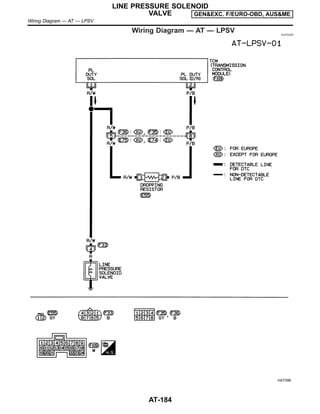
Line pressure solenoid
valve
LINE PRESSURE S/V I TCM detects an improper voltage drop when it tries
to operate the solenoid valve.
TCM (RAM) CONTROL UNIT
(RAM)
I TCM memory (RAM) is malfunctioning.
TCM (ROM) CONTROL UNIT
(ROM)
I TCM memory (ROM) is malfunctioning.
TCM (EEP ROM) CONT UNIT (EEP
ROM)
I TCM memory (EEP ROM) is malfunctioning.
DATA MONITOR MODE (A/T) NJAT0022S04
Item Display
Monitor item
Description Remarks
TCM input
signals
Main sig-
nals
Vehicle speed sensor 1
(A/T)
(Revolution sensor)
VHCL/S SE·A/T
[km/h] or [mph]
X —
I Vehicle speed computed
from signal of revolution
sensor is displayed.
When racing engine in “N”
or “P” position with vehicle
stationary, CONSULT-II
data may not indicate 0
km/h (0 mph).
GI
MA
EM
LC
EC
FE
CL
MT
AX
SU
BR
ST
RS
BT
HA
SC
EL
IDX
ON BOARD DIAGNOSTIC SYSTEM
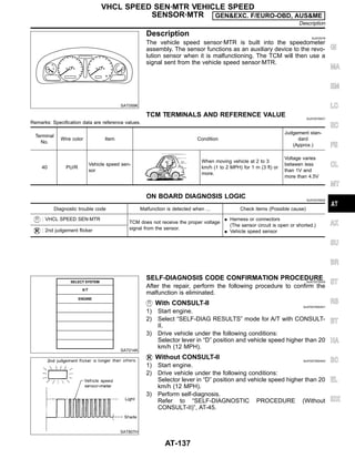
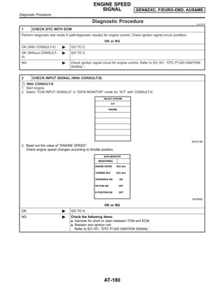
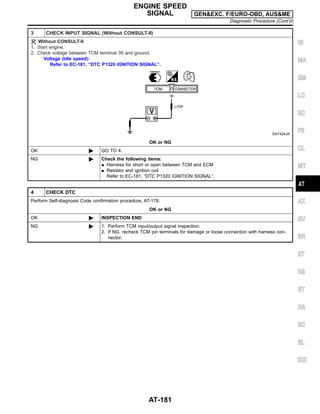
DESCRIPTION GEN&EXC. F/EURO-OBD, AUS&ME
CONSULT-II (Cont’d)
AT-41](https://image.slidesharecdn.com/at-230609060207-eaf4eb52/85/at-pdf-41-320.jpg)
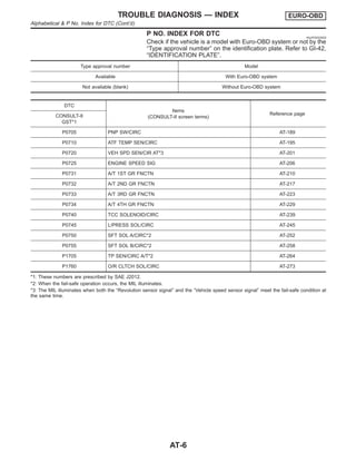
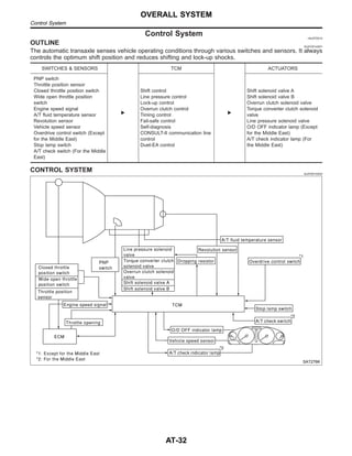
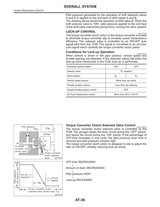
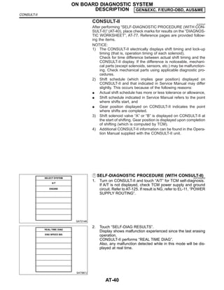
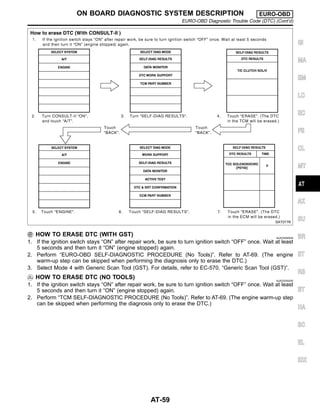
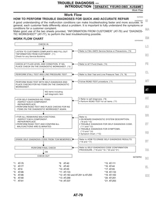
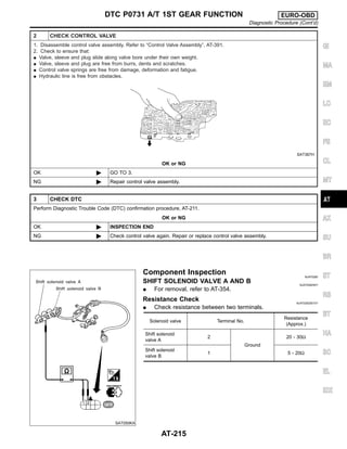
![Item Display
Monitor item
Description Remarks
TCM input
signals
Main sig-
nals
Vehicle speed sensor 2
(Meter)
VHCL/S SE·MTR
[km/h] or [mph]
X —
I Vehicle speed computed
from signal of vehicle
speed sensor is dis-
played.
Vehicle speed display may
not be accurate under
approx. 10 km/h (6 mph).
It may not indicate 0 km/h
(0 mph) when vehicle is
stationary.
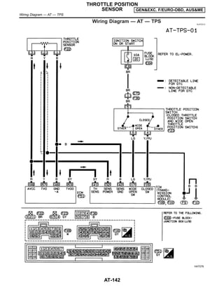
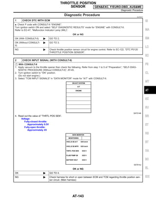
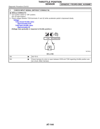
Throttle position sensor THRTL POS SEN
[V] X —
I Throttle position sensor
signal voltage is dis-
played.
A/T fluid temperature sen-
sor
FLUID TEMP SE
[V]
X —
I A/T fluid temperature
sensor signal voltage is
displayed.
I Signal voltage lowers as
fluid temperature rises.
Battery voltage BATTERY VOLT
[V]
X —
I Source voltage of TCM
is displayed.
Engine speed ENGINE SPEED
[rpm]
X X
I Engine speed, com-
puted from engine
speed signal, is dis-
played.
Engine speed display may
not be accurate under
approx. 800 rpm. It may
not indicate 0 rpm even
when engine is not run-
ning.
Overdrive control switch OVERDRIVE SW
[ON/OFF] X —
I ON/OFF state computed
from signal of overdrive
control SW is displayed.
PN position switch PN POSI SW
[ON/OFF] X —
I ON/OFF state computed
from signal of PN posi-
tion SW is displayed.
R position switch R POSITION SW
[ON/OFF] X —
I ON/OFF state computed
from signal of R position
SW is displayed.
D position switch D POSITION SW
[ON/OFF] X —
I ON/OFF state computed
from signal of D position
SW is displayed.
2 position switch 2 POSITION SW
[ON/OFF]
X —
I ON/OFF status, com-
puted from signal of 2
position SW, is dis-
played.
1 position switch 1 POSITION SW
[ON/OFF]
X —
I ON/OFF status, com-
puted from signal of 1
position SW, is dis-
played.
ASCD cruise signal ASCD-CRUISE
[ON/OFF]
X —
I Status of ASCD cruise
signal is displayed.
ON ... Cruising state
OFF ... Normal running
state
I This is displayed even
when no ASCD is
mounted.
ASCD OD cut signal ASCD-OD CUT
[ON/OFF]
X —
I Status of ASCD OD
release signal is dis-
played.
ON ... OD released
OFF ... OD not released
I This is displayed even
when no ASCD is
mounted.
ON BOARD DIAGNOSTIC SYSTEM
DESCRIPTION GEN&EXC. F/EURO-OBD, AUS&ME
CONSULT-II (Cont’d)
AT-42](https://image.slidesharecdn.com/at-230609060207-eaf4eb52/85/at-pdf-42-320.jpg)
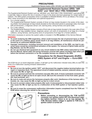
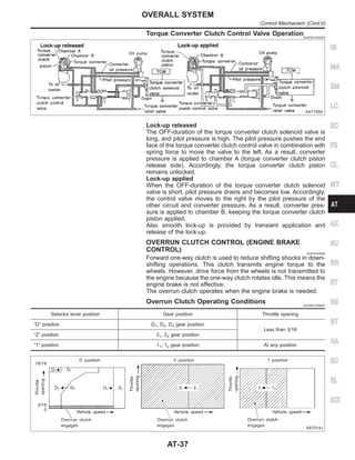
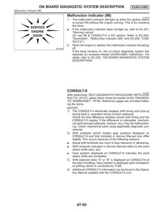
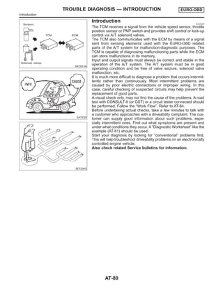
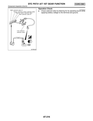
![Item Display
Monitor item
Description Remarks
TCM input
signals
Main sig-
nals
Kickdown switch KICKDOWN SW
[ON/OFF]
X —
I ON/OFF status, com-
puted from signal of
kickdown SW, is dis-
played.
I This is displayed even
when no kickdown
switch is equipped.
Closed throttle position
switch
CLOSED
THL/SW
[ON/OFF]
X —
I ON/OFF status, com-
puted from signal of
closed throttle position
SW, is displayed.
Wide open throttle position
switch
W/O THRL/P-SW
[ON/OFF]
X —
I ON/OFF status, com-
puted from signal of
wide open throttle posi-
tion SW, is displayed.
Gear position GEAR
— X
I Gear position data used
for computation by TCM,
is displayed.
Selector lever position SLCT LVR POSI
— X
I Selector lever position
data, used for computa-
tion by TCM, is dis-
played.
I A specific value used for
control is displayed if
fail-safe is activated due
to error.
Vehicle speed VEHICLE SPEED
[km/h] or [mph] — X
I Vehicle speed data,
used for computation by
TCM, is displayed.
Stop lamp switch BRAKE SW
[ON/OFF]
X —
I ON/OFF status are dis-
played.
ON: Brake pedal is
depressed.
OFF: Brake pedal is
released.
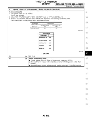
Throttle position THROTTLE POSI
[/8]
— X
I Throttle position data,
used for computation by
TCM, is displayed.
I A specific value used for
control is displayed if
fail-safe is activated due
to error.
Line pressure duty LINE PRES DTY
[%]
— X
I Control value of line
pressure solenoid valve,
computed by TCM from
each input signal, is dis-
played.
Torque converter clutch
solenoid valve duty
TCC S/V DUTY
[%]
— X
I Control value of torque
converter clutch sole-
noid valve, computed by
TCM from each input
signal, is displayed.
Shift solenoid valve A SHIFT S/V A
[ON/OFF]
— X
I Control value of shift
solenoid valve A, com-
puted by TCM from
each input signal, is dis-
played.
Control value of solenoid
is displayed even if sole-
noid circuit is discon-
nected.
The “OFF” signal is dis-
played if solenoid circuit is
shorted.
Shift solenoid valve B SHIFT S/V B
[ON/OFF]
— X
I Control value of shift
solenoid valve B, com-
puted by TCM from
each input signal, is dis-
played.
GI
MA
EM
LC
EC
FE
CL
MT
AX
SU
BR
ST
RS
BT
HA
SC
EL
IDX
ON BOARD DIAGNOSTIC SYSTEM
DESCRIPTION GEN&EXC. F/EURO-OBD, AUS&ME
CONSULT-II (Cont’d)
AT-43](https://image.slidesharecdn.com/at-230609060207-eaf4eb52/85/at-pdf-43-320.jpg)
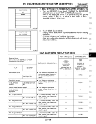
![Item Display
Monitor item
Description Remarks
TCM input
signals
Main sig-
nals
Overrun clutch solenoid
valve
OVERRUN/C S/V
[ON/OFF]
— X
I Control value of overrun
clutch solenoid valve
computed by TCM from
each input signal is dis-
played.
Self-diagnosis display
lamp
(O/D OFF indicator lamp)
SELF-D DP LMP
[ON/OFF] — X
I Control status of O/D
OFF indicator lamp is
displayed.
X: Applicable
—: Not applicable
SAT014K
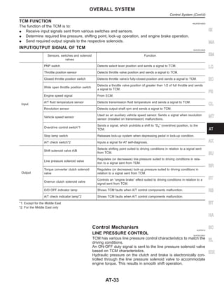
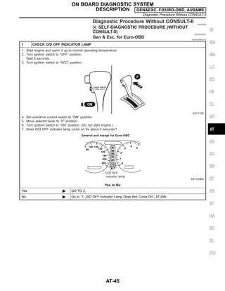
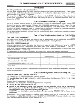
HOW TO ERASE SELF-DIAGNOSTIC RESULTS
( WITH CONSULT-II) NJAT0022S08
1. If the ignition switch stays “ON” after repair work, be sure to
turn ignition switch “OFF” once. Wait for at least 3 seconds and
then turn it “ON” again.
2. Turn CONSULT-II “ON”, and touch “A/T”.
SAT971J
3. Touch “SELF-DIAG RESULTS”.
SAT970J
4. Touch “ERASE”. (The self-diagnostic results will be erased.)
ON BOARD DIAGNOSTIC SYSTEM
DESCRIPTION GEN&EXC. F/EURO-OBD, AUS&ME
CONSULT-II (Cont’d)
AT-44](https://image.slidesharecdn.com/at-230609060207-eaf4eb52/85/at-pdf-44-320.jpg)
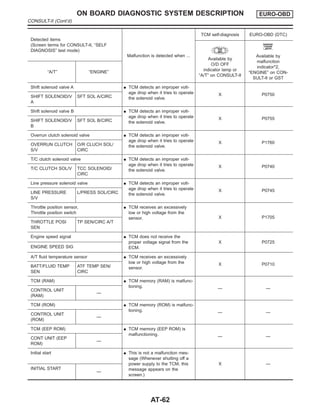
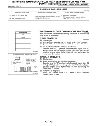
![Detected items
(Screen terms for CONSULT-II, “SELF
DIAGNOSIS” test mode)
Malfunction is detected when ...
TCM self-diagnosis EURO-OBD (DTC)
Available by
O/D OFF
indicator lamp or
“A/T” on CONSULT-II
Available by
malfunction
indicator*2,
“ENGINE” on CON-
SULT-II or GST
“A/T” “ENGINE”
No failure
(NO SELF DIAGNOSTIC FAILURE INDI-
CATED FURTHER TESTING MAY BE
REQUIRED**)
I No failure has been detected.
X X
X: Applicable
—: Not applicable
*1: These malfunctions cannot be displayed by MI if another malfunction is assigned to MI.
*2: Refer to EC-550, “Malfunction Indicator (MI)”.
DATA MONITOR MODE (A/T) NJAT0256S03
Item Display
Monitor item
Description Remarks
TCM input
signals
Main sig-
nals
Vehicle speed sensor 1
(A/T)
(Revolution sensor)
VHCL/S SE·A/T
[km/h] or [mph]
X —
I Vehicle speed computed
from signal of revolution
sensor is displayed.
When racing engine in “N”
or “P” position with vehicle
stationary, CONSULT-II
data may not indicate 0
km/h (0 mph).
Vehicle speed sensor 2
(Meter)
VHCL/S SE·MTR
[km/h] or [mph]
X —
I Vehicle speed computed
from signal of vehicle
speed sensor is dis-
played.
Vehicle speed display may
not be accurate under
approx. 10 km/h (6 mph). It
may not indicate 0 km/h (0
mph) when vehicle is sta-
tionary.
Throttle position sensor THRTL POS
SEN
[V]
X —
I Throttle position sensor
signal voltage is dis-
played.
A/T fluid temperature sen-
sor
FLUID TEMP SE
[V]
X —
I A/T fluid temperature
sensor signal voltage is
displayed.
I Signal voltage lowers as
fluid temperature rises.
Battery voltage BATTERY VOLT
[V]
X —
I Source voltage of TCM
is displayed.
Engine speed ENGINE SPEED
[rpm]
X X
I Engine speed, computed
from engine speed
signal, is displayed.
Engine speed display may
not be accurate under
approx. 800 rpm. It may
not indicate 0 rpm even
when engine is not run-
ning.
Overdrive control switch OVERDRIVE SW
[ON/OFF] X —
I ON/OFF state computed
from signal of overdrive
control SW is displayed.
P/N position switch PN POSI SW
[ON/OFF] X —
I ON/OFF state computed
from signal of P/N posi-
tion SW is displayed.
GI
MA
EM
LC
EC
FE
CL
MT
AX
SU
BR
ST
RS
BT
HA
SC
EL
IDX
ON BOARD DIAGNOSTIC SYSTEM DESCRIPTION EURO-OBD
CONSULT-II (Cont’d)
AT-63](https://image.slidesharecdn.com/at-230609060207-eaf4eb52/85/at-pdf-63-320.jpg)
![Item Display
Monitor item
Description Remarks
TCM input
signals
Main sig-
nals
R position switch R POSITION SW
[ON/OFF] X —
I ON/OFF state computed
from signal of R position
SW is displayed.
D position switch D POSITION SW
[ON/OFF] X —
I ON/OFF state computed
from signal of D position
SW is displayed.
2 position switch 2 POSITION SW
[ON/OFF]
X —
I ON/OFF status, com-
puted from signal of 2
position SW, is dis-
played.
1 position switch 1 POSITION SW
[ON/OFF]
X —
I ON/OFF status, com-
puted from signal of 1
position SW, is dis-
played.
ASCD cruise signal ASCD-CRUISE
[ON/OFF]
X —
I Status of ASCD cruise
signal is displayed.
ON ... Cruising state
OFF ... Normal running
state
I This is displayed even
when no ASCD is
mounted.
ASCD OD cut signal ASCD-OD CUT
[ON/OFF]
X —
I Status of ASCD OD
release signal is dis-
played.
ON ... OD released
OFF ... OD not released
I This is displayed even
when no ASCD is
mounted.
Kickdown switch KICKDOWN SW
[ON/OFF]
X —
I ON/OFF status, com-
puted from signal of
kickdown SW, is dis-
played.
I This is displayed even
when no kickdown
switch is equipped.
Closed throttle position
switch
CLOSED
THL/SW
[ON/OFF]
X —
I ON/OFF status, com-
puted from signal of
closed throttle position
SW, is displayed.
Wide open throttle position
switch
W/O THRL/P-SW
[ON/OFF]
X —
I ON/OFF status, com-
puted from signal of
wide open throttle posi-
tion SW, is displayed.
Gear position GEAR
— X
I Gear position data used
for computation by TCM,
is displayed.
Selector lever position SLCT LVR POSI
— X
I Selector lever position
data, used for computa-
tion by TCM, is dis-
played.
I A specific value used for
control is displayed if
fail-safe is activated due
to error.
Vehicle speed VEHICLE
SPEED
[km/h] or [mph]
— X
I Vehicle speed data,
used for computation by
TCM, is displayed.
Stop lamp switch BRAKE SW
[ON/OFF]
X —
I ON/OFF status are dis-
played.
ON: Brake pedal is
depressed.
OFF: Brake pedal is
released.
ON BOARD DIAGNOSTIC SYSTEM DESCRIPTION EURO-OBD
CONSULT-II (Cont’d)
AT-64](https://image.slidesharecdn.com/at-230609060207-eaf4eb52/85/at-pdf-64-320.jpg)
![Item Display
Monitor item
Description Remarks
TCM input
signals
Main sig-
nals
Throttle position THROTTLE
POSI
[/8]
— X
I Throttle position data,
used for computation by
TCM, is displayed.
I A specific value used for
control is displayed if
fail-safe is activated due
to error.
Line pressure duty LINE PRES DTY
[%]
— X
I Control value of line
pressure solenoid valve,
computed by TCM from
each input signal, is dis-
played.
Torque converter clutch
solenoid valve duty
TCC S/V DUTY
[%]
— X
I Control value of torque
converter clutch solenoid
valve, computed by
TCM from each input
signal, is displayed.
Shift solenoid valve A SHIFT S/V A
[ON/OFF]
— X
I Control value of shift
solenoid valve A, com-
puted by TCM from
each input signal, is dis-
played.
Control value of solenoid is
displayed even if solenoid
circuit is disconnected.
The “OFF” signal is dis-
played if solenoid circuit is
shorted.
Shift solenoid valve B SHIFT S/V B
[ON/OFF]
— X
I Control value of shift
solenoid valve B, com-
puted by TCM from
each input signal, is dis-
played.
Overrun clutch solenoid
valve
OVERRUN/C S/V
[ON/OFF]
— X
I Control value of overrun
clutch solenoid valve
computed by TCM from
each input signal is dis-
played.
Self-diagnosis display lamp
(O/D OFF indicator lamp)
SELF-D DP LMP
[ON/OFF] — X
I Control status of O/D
OFF indicator lamp is
displayed.
X: Applicable
—: Not applicable
SAT998J
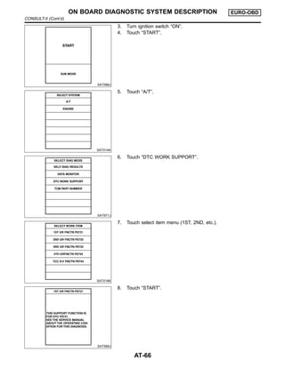
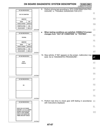
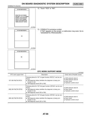
DTC WORK SUPPORT MODE WITH CONSULT-II NJAT0256S04
CONSULT-II Setting Procedure NJAT0256S0401
1. Turn ignition switch “OFF”.
2. Connect CONSULT-II to data link connector which is located
in left side lower dash panel.
GI
MA
EM
LC
EC
FE
CL
MT
AX
SU
BR
ST
RS
BT
HA
SC
EL
IDX
ON BOARD DIAGNOSTIC SYSTEM DESCRIPTION EURO-OBD
CONSULT-II (Cont’d)
AT-65](https://image.slidesharecdn.com/at-230609060207-eaf4eb52/85/at-pdf-65-320.jpg)


![SAT283HC
SAT021J
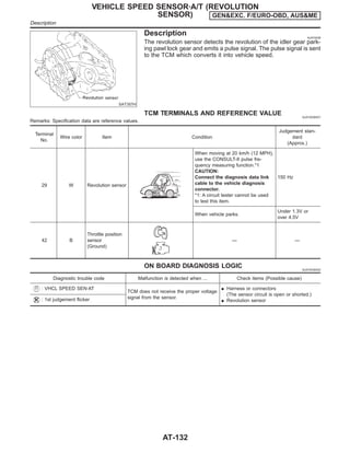
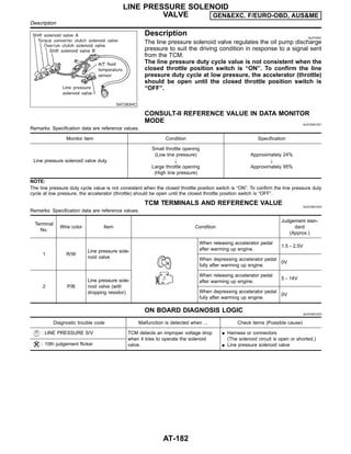
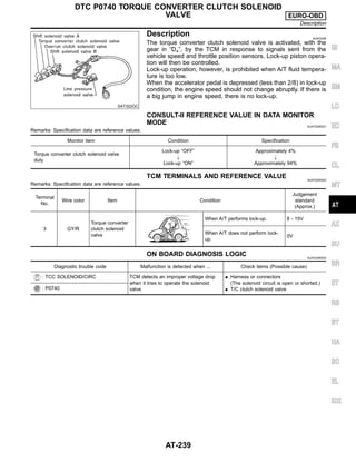
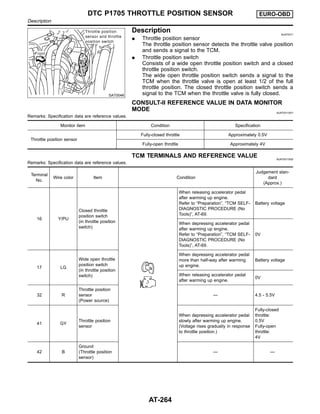
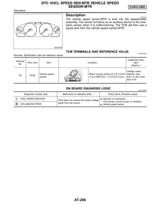
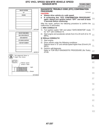
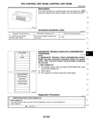
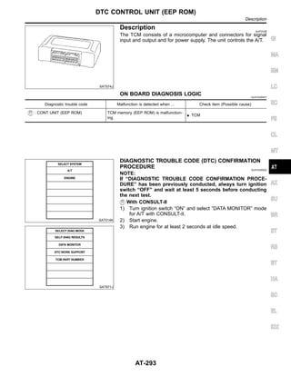
Description NJAT0076
The A/T fluid temperature sensor detects the A/T fluid temperature
and sends a signal to the TCM.
CONSULT-II REFERENCE VALUE IN DATA MONITOR
MODE NJAT0076S01
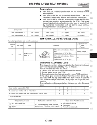
Remarks: Specification data are reference values.
Monitor item Condition Specification (Approximately)
A/T fluid temperature sensor
Cold [20°C (68°F)]
"
Hot [80°C (176°F)]
1.5V
"
0.5V
2.5 kΩ
"
0.3 kΩ
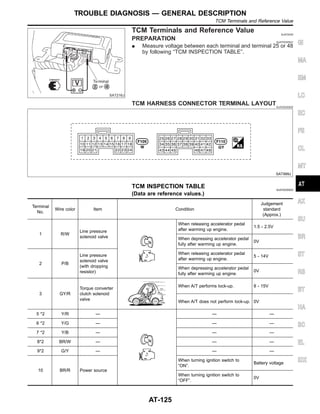
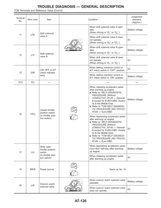
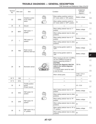
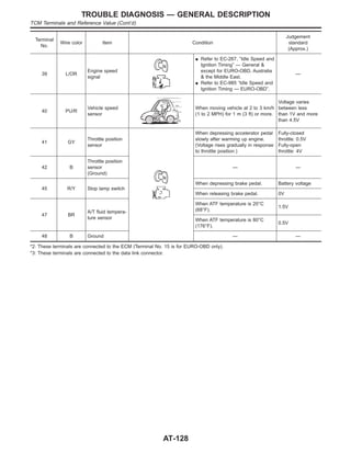
TCM TERMINALS AND REFERENCE VALUE NJAT0076S02
Remarks: Specification data are reference values.
Terminal
No.
Wire color Item Condition
Judgement
standard
(Approx.)
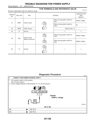
10 BR/R Power source
When turning ignition switch to
“ON”.
Battery voltage
When turning ignition switch to
“OFF”.
0V
19 BR/R Power source Same as No. 10
28 R/B
Power source
(Memory back-up)
or
When turning ignition switch to
“OFF”.
Battery voltage
When turning ignition switch to
“ON”.
Battery voltage
42 B
Ground
(A/T fluid tempera-
ture sensor)
— —
47 BR
A/T fluid tempera-
ture sensor
When ATF temperature is 20°C
(68°F).
1.5V
When ATF temperature is 80°C
(176°F).
0.5V
GI
MA
EM
LC
EC
FE
CL
MT
AX
SU
BR
ST
RS
BT
HA
SC
EL
IDX
BATT/FLUID TEMP SEN (A/T FLUID TEMP SENSOR CIRCUIT AND TCM
POWER SOURCE) GEN&EXC. F/EURO-OBD, AUS&ME
Description
AT-171](https://image.slidesharecdn.com/at-230609060207-eaf4eb52/85/at-pdf-171-320.jpg)
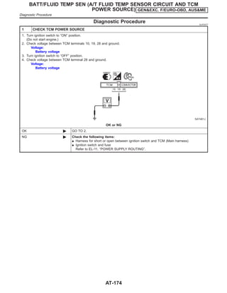
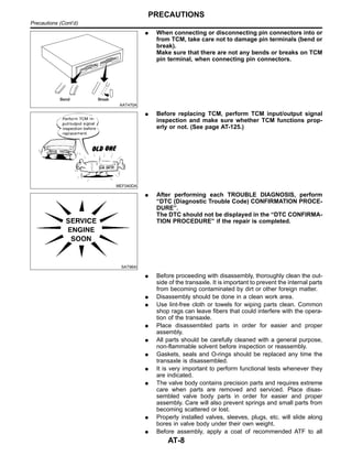
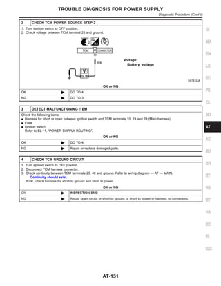
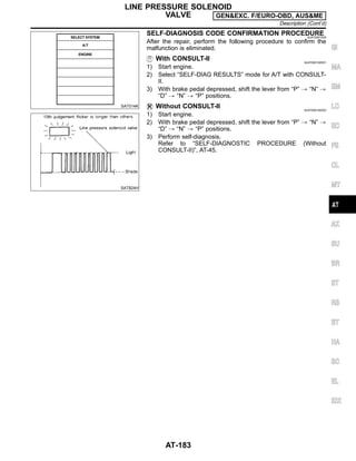
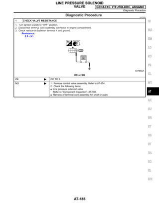
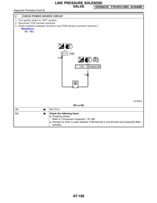
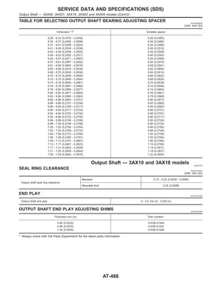
![2 CHECK A/T FLUID TEMPERATURE SENSOR WITH TERMINAL CORD ASSEMBLY
1. Turn ignition switch to “OFF” position.
2. Disconnect terminal cord assembly connector in engine compartment.
3. Check resistance between terminals 6 and 7 when A/T is cold.
Resistance:
Cold [20°C (68°F)]
Approximately 2.5 kΩ
SAT912JA
4. Reinstall any part removed.
OK or NG
OK (With CONSULT-II) © GO TO 3.
OK (Without CONSULT-
II)
© GO TO 4.
NG © 1. Remove oil pan.
2. Check the following items:
I A/T fluid temperature sensor
Refer to “Component Inspection”, AT-177.
I Harness of terminal cord assembly for short or open
3 CHECK INPUT SIGNAL OF A/T FLUID TEMPERATURE SENSOR (WITH CONSULT-II)
With CONSULT-II
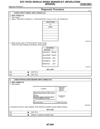
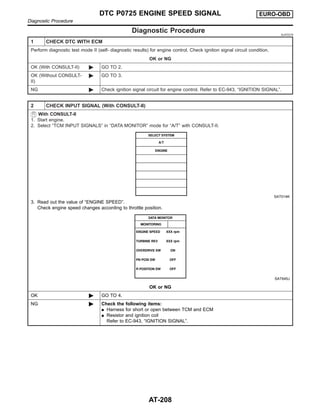
1. Start engine.
2. Select “TCM INPUT SIGNALS” in “DATA MONITOR” mode for “A/T” with CONSULT-II.
3. Read out the value of “FLUID TEMP SE”.
Voltage:
Cold [20°C (68°F)] → Hot [80°C (176°F)]:
Approximately 1.5V → 0.5V
SAT614J
OK or NG
OK © GO TO 5.
NG © Check the following item:
I Harness for short or open between TCM, ECM and terminal cord assembly (Main har-
ness)
I Ground circuit for ECM
Refer to EC-102, “TROUBLE DIAGNOSIS FOR POWER SUPPLY”.
GI
MA
EM
LC
EC
FE
CL
MT
AX
SU
BR
ST
RS
BT
HA
SC
EL
IDX
BATT/FLUID TEMP SEN (A/T FLUID TEMP SENSOR CIRCUIT AND TCM
POWER SOURCE) GEN&EXC. F/EURO-OBD, AUS&ME
Diagnostic Procedure (Cont’d)
AT-175](https://image.slidesharecdn.com/at-230609060207-eaf4eb52/85/at-pdf-175-320.jpg)
![4 CHECK INPUT SIGNAL OF A/T FLUID TEMPERATURE SENSOR (WITHOUT CONSULT-II)
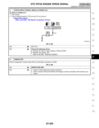
Without CONSULT-II
1. Start engine.
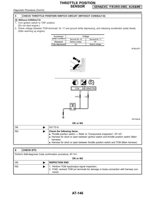
2. Check voltage between TCM terminal 47 and ground while warming up A/T.
Voltage:
Cold [20°C (68°F)] → Hot [80°C (176°F)]:
Approximately 1.5V → 0.5V
SAT463J
3. Turn ignition switch to “OFF” position.
4. Disconnect TCM harness connector.
5. Check resistance between terminal 42 and ground.
Continuity should exist.
SAT464J
OK or NG
OK © GO TO 5.
NG © Check the following item:
I Harness for short or open between TCM, ECM and terminal cord assembly (Main har-
ness)
I Ground circuit for ECM
Refer to EC-102, “TROUBLE DIAGNOSIS FOR POWER SUPPLY”.
5 CHECK DTC
Perform Self-diagnosis Code confirmation procedure, AT-172.
OK or NG
OK © INSPECTION END
NG © 1. Perform TCM input/output signal inspection.
2. If NG, recheck TCM pin terminals for damage or loose connection with harness con-
nector.
BATT/FLUID TEMP SEN (A/T FLUID TEMP SENSOR CIRCUIT AND TCM
POWER SOURCE) GEN&EXC. F/EURO-OBD, AUS&ME
Diagnostic Procedure (Cont’d)
AT-176](https://image.slidesharecdn.com/at-230609060207-eaf4eb52/85/at-pdf-176-320.jpg)
![SAT322GC
SAT021J
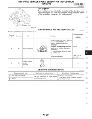
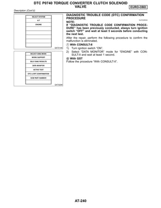
Description NJAT0268
The A/T fluid temperature sensor detects the A/T fluid temperature
and sends a signal to the TCM.
CONSULT-II REFERENCE VALUE IN DATA MONITOR
MODE NJAT0268S01
Remarks: Specification data are reference values.
Monitor item Condition Specification (Approximately)
A/T fluid temperature sensor
Cold [20°C (68°F)]
"
Hot [80°C (176°F)]
1.5V
"
0.5V
2.5 kΩ
"
0.3 kΩ
TCM TERMINALS AND REFERENCE VALUE NJAT0268S02
Remarks: Specification data are reference values.
Terminal
No.
Wire color Item Condition
Judgement stan-
dard
(Approx.)
42 B
Throttle position
sensor
(Ground)
— —
47 BR
A/T fluid tempera-
ture sensor
When ATF temperature is 20°C
(68°F).
1.5V
When ATF temperature is 80°C
(176°F).
0.5V
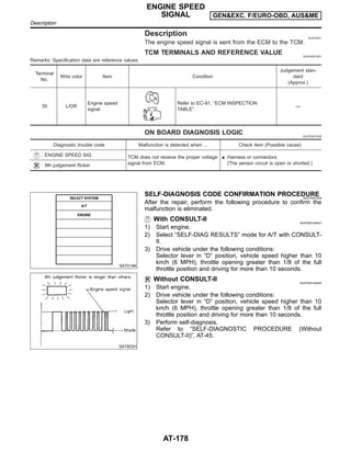
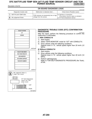
ON BOARD DIAGNOSIS LOGIC NJAT0268S03
Diagnostic trouble code Malfunction is detected when ... Check items (Possible cause)
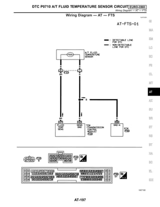
: ATF TEMP SEN/CIRC
TCM receives an excessively low or high
voltage from the sensor.
I Harness or connectors
(The sensor circuit is open or shorted.)
I A/T fluid temperature sensor
: P0710
GI
MA
EM
LC
EC
FE
CL
MT
AX
SU
BR
ST
RS
BT
HA
SC
EL
IDX
DTC P0710 A/T FLUID TEMPERATURE SENSOR CIRCUIT EURO-OBD
Description
AT-195](https://image.slidesharecdn.com/at-230609060207-eaf4eb52/85/at-pdf-195-320.jpg)
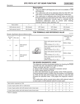
![Diagnostic Procedure NJAT0270
1 INSPECTION START
Do you have CONSULT-II?
Yes or No
Yes © GO TO 2.
No © GO TO 3.
2 CHECK INPUT SIGNAL OF A/T FLUID TEMPERATURE SENSOR (With CONSULT-II)
With CONSULT-II
1. Start engine.
2. Select “TCM INPUT SIGNALS” in “DATA MONITOR” mode for “A/T” with CONSULT-II.
SAT014K
3. Read out the value of “FLUID TEMP SE”.
Voltage:
Cold [20°C (68°F)] → Hot [80°C (176°F)]:
Approximately 1.5V → 0.5V
SAT614J
OK or NG
OK © GO TO 4.
NG © GO TO 5.
DTC P0710 A/T FLUID TEMPERATURE SENSOR CIRCUIT EURO-OBD
Diagnostic Procedure
AT-198](https://image.slidesharecdn.com/at-230609060207-eaf4eb52/85/at-pdf-198-320.jpg)
![3 CHECK INPUT SIGNAL OF A/T FLUID TEMPERATURE SENSOR (Without CONSULT-II)
Without CONSULT-II
1. Start engine.
2. Check voltage between TCM terminal 47 and ground while warming up A/T.
Voltage:
Cold [20°C (68°F)] → Hot [80°C (176°F)]:
Approximately 1.5V → 0.5V
SAT937J
3. Turn ignition switch to “OFF” position.
4. Disconnect TCM harness connector.
5. Check continuity between terminal 42 and ground.
Continuity should exist.
SAT421J
If OK, check harness for short to ground and short to power.
OK or NG
OK © GO TO 4.
NG © GO TO 5.
4 CHECK DTC
Perform Diagnostic Trouble Code (DTC) confirmation procedure, AT-196.
OK or NG
OK © INSPECTION END
NG © 1. Perform TCM input/output signal inspection.
2. If NG, recheck TCM pin terminals for damage or loose connection with harness con-
nector.
GI
MA
EM
LC
EC
FE
CL
MT
AX
SU
BR
ST
RS
BT
HA
SC
EL
IDX
DTC P0710 A/T FLUID TEMPERATURE SENSOR CIRCUIT EURO-OBD
Diagnostic Procedure (Cont’d)
AT-199](https://image.slidesharecdn.com/at-230609060207-eaf4eb52/85/at-pdf-199-320.jpg)
![5 CHECK A/T FLUID TEMPERATURE SENSOR WITH TERMINAL CORD ASSEMBLY
1. Turn ignition switch to “OFF” position.
2. Disconnect terminal cord assembly connector in engine compartment.
3. Check resistance between terminals 6 and 7 when A/T is cold.
Resistance:
Cold [20°C (68°F)]
Approximately 2.5 kΩ
SAT880JA
4. Reinstall any part removed.
OK or NG
OK (With CONSULT-II) © GO TO 2.
OK (Without CONSULT-
II)
© GO TO 3.
NG © 1. Remove oil pan.
2. Check the following items:
I A/T fluid temperature sensor
Refer to “Component Inspection”, AT-200.
I Harness of terminal cord assembly for short or open
SAT298F
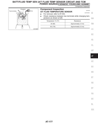
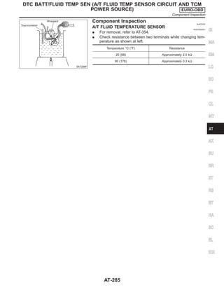
Component Inspection NJAT0271
A/T FLUID TEMPERATURE SENSOR NJAT0271S01
I For removal, refer to AT-354.
I Check resistance between two terminals while changing tem-
perature as shown at left.
Temperature °C (°F) Resistance
20 (68) Approximately 2.5 kΩ
80 (176) Approximately 0.3 kΩ
DTC P0710 A/T FLUID TEMPERATURE SENSOR CIRCUIT EURO-OBD
Diagnostic Procedure (Cont’d)
AT-200](https://image.slidesharecdn.com/at-230609060207-eaf4eb52/85/at-pdf-200-320.jpg)


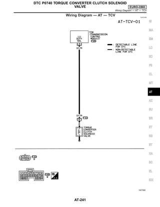


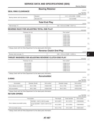
![SAT851JA
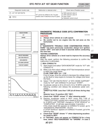
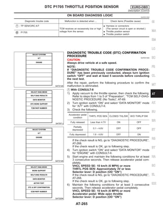
Component Inspection =NJAT0314
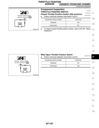
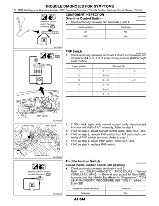
THROTTLE POSITION SWITCH NJAT0314S01
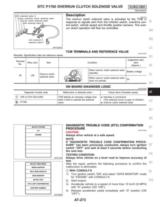
Closed Throttle Position Switch (Idle position) NJAT0314S0101
I Check continuity between terminals 4 and 5.
[Refer to “Preparation”, “TCM SELF-DIAGNOSTIC PROCE-
DURE (No Tools)”, AT-69.]
Accelerator pedal condition Continuity
Released Yes
Depressed No
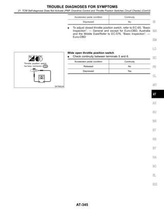
I To adjust closed throttle position switch, refer to EC-803, “DTC
P0510 CLOSED THROTTLE POSITION SWITCH”.
SAT852JA
Wide Open Throttle Position Switch NJAT0314S0102
I Check continuity between terminals 5 and 6.
Accelerator pedal condition Continuity
Released No
Depressed Yes
DTC P1705 THROTTLE POSITION SENSOR EURO-OBD
Component Inspection
AT-272](https://image.slidesharecdn.com/at-230609060207-eaf4eb52/85/at-pdf-272-320.jpg)

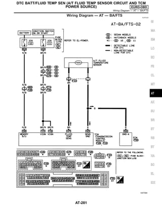
![SAT322GC
SAT021J
Description NJAT0319
The A/T fluid temperature sensor detects the A/T fluid temperature
and sends a signal to the TCM.
CONSULT-II REFERENCE VALUE IN DATA MONITOR
MODE NJAT0319S01
Remarks: Specification data are reference values.
Monitor item Condition Specification (Approximately)
A/T fluid temperature sensor
Cold [20°C (68°F)]
"
Hot [80°C (176°F)]
1.5V
"
0.5V
2.5 kΩ
"
0.3 kΩ
TCM TERMINALS AND REFERENCE VALUE NJAT0319S02
Remarks: Specification data are reference values.
Terminal
No.
Wire color Item Condition
Judgement stan-
dard
(Approx.)
10 BR/R Power source
When turning ignition switch to
“ON”.
Battery voltage
When turning ignition switch to
“OFF”.
0V
19 BR/R Power source Same as No. 10
28 R/B
Power source
(Memory back-up)
or
When turning ignition switch to
“OFF”.
Battery voltage
When turning ignition switch to
“ON”.
Battery voltage
42 B
Ground
(A/T fluid tem-
perature sensor)
— —
47 BR
A/T fluid tempera-
ture sensor
When ATF temperature is 20°C
(68°F).
1.5V
When ATF temperature is 80°C
(176°F).
0.5V
GI
MA
EM
LC
EC
FE
CL
MT
AX
SU
BR
ST
RS
BT
HA
SC
EL
IDX
DTC BATT/FLUID TEMP SEN (A/T FLUID TEMP SENSOR CIRCUIT AND TCM
POWER SOURCE) EURO-OBD
Description
AT-279](https://image.slidesharecdn.com/at-230609060207-eaf4eb52/85/at-pdf-279-320.jpg)
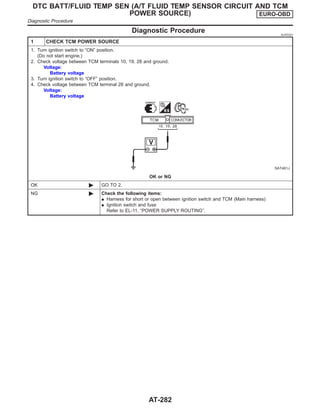
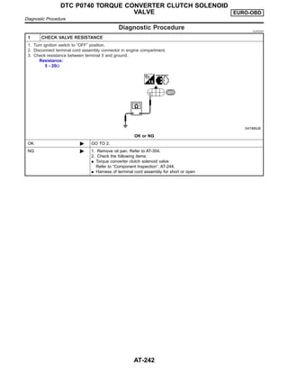
![2 CHECK A/T FLUID TEMPERATURE SENSOR WITH TERMINAL CORD ASSEMBLY
1. Turn ignition switch to “OFF” position.
2. Disconnect terminal cord assembly connector in engine compartment.
3. Check resistance between terminals 6 and 7 when A/T is cold.
Resistance:
Cold [20°C (68°F)]
Approximately 2.5 kΩ
SAT912JB
4. Reinstall any part removed.
OK or NG
OK (With CONSULT-II) © GO TO 3.
OK (Without CONSULT-
II)
© GO TO 4.
NG © 1. Remove oil pan.
2. Check the following items:
I A/T fluid temperature sensor
Refer to “Component Inspection”, AT-285.
I Harness of terminal cord assembly for short or open
3 CHECK INPUT SIGNAL OF A/T FLUID TEMPERATURE SENSOR (WITH CONSULT-II)
With CONSULT-II
1. Start engine.
2. Select “TCM INPUT SIGNALS” in “DATA MONITOR” mode for “A/T” with CONSULT-II.
3. Read out the value of “FLUID TEMP SE”.
Voltage:
Cold [20°C (68°F)] → Hot [80°C (176°F)]:
Approximately 1.5V → 0.5V
SAT614J
OK or NG
OK © GO TO 5.
NG © Check the following item:
I Harness for short or open between TCM, ECM and terminal cord assembly (Main har-
ness)
I Ground circuit for ECM
Refer to EC-615, “TROUBLE DIAGNOSIS FOR POWER SUPPLY”.
GI
MA
EM
LC
EC
FE
CL
MT
AX
SU
BR
ST
RS
BT
HA
SC
EL
IDX
DTC BATT/FLUID TEMP SEN (A/T FLUID TEMP SENSOR CIRCUIT AND TCM
POWER SOURCE) EURO-OBD
Diagnostic Procedure (Cont’d)
AT-283](https://image.slidesharecdn.com/at-230609060207-eaf4eb52/85/at-pdf-283-320.jpg)
![4 CHECK INPUT SIGNAL OF A/T FLUID TEMPERATURE SENSOR (WITHOUT CONSULT-II)
Without CONSULT-II
1. Start engine.
2. Check voltage between TCM terminal 47 and ground while warming up A/T.
Voltage:
Cold [20°C (68°F)] → Hot [80°C (176°F)]:
Approximately 1.5V → 0.5V
SAT463J
3. Turn ignition switch to “OFF” position.
4. Disconnect TCM harness connector.
5. Check resistance between terminal 42 and ground.
Continuity should exist.
SAT464J
OK or NG
OK © GO TO 5.
NG © Check the following item:
I Harness for short or open between TCM, ECM and terminal cord assembly (Main har-
ness)
I Ground circuit for ECM
Refer to EC-615, “TROUBLE DIAGNOSIS FOR POWER SUPPLY”.
5 CHECK DTC
Perform Diagnostic Trouble Code (DTC) confirmation procedure, AT-280.
OK or NG
OK © INSPECTION END
NG © 1. Perform TCM input/output signal inspection.
2. If NG, recheck TCM pin terminals for damage or loose connection with harness con-
nector.
DTC BATT/FLUID TEMP SEN (A/T FLUID TEMP SENSOR CIRCUIT AND TCM
POWER SOURCE) EURO-OBD
Diagnostic Procedure (Cont’d)
AT-284](https://image.slidesharecdn.com/at-230609060207-eaf4eb52/85/at-pdf-284-320.jpg)


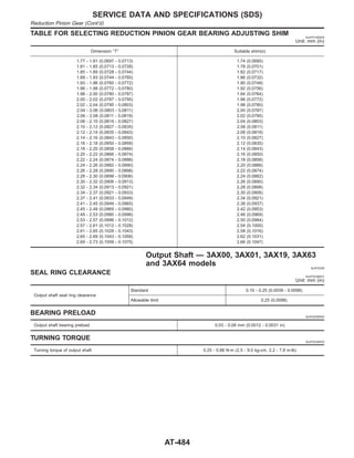
![Band Servo NJAT0196
RETURN SPRING NJAT0196S01
Unit: mm (in)
Return spring Free length Outer diameter Part number*
2nd servo return spring 32.5 (1.280) 25.9 (1.020) 31605-31X20
OD servo return spring 38.52 (1.5165) 22.0 (0.866) 31605-31X21
*: Always check with the Parts Department for the latest parts information.
Removal and Installation NJAT0197
Unit: mm (in)
Distance between end of converter housing and torque converter 15.9 (0.626) or more
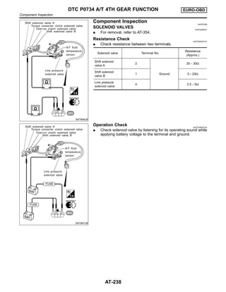
Shift Solenoid Valves NJAT0223
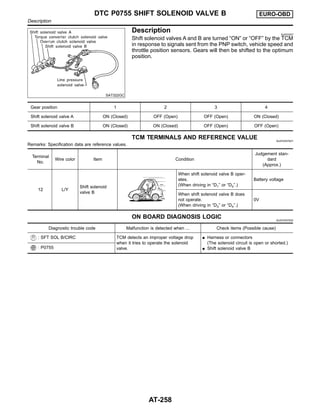
Gear Solenoid A Solenoid B
1st ON ON
2nd OFF ON
3rd OFF OFF
4th ON OFF
Solenoid Valves NJAT0224
Solenoid valve Resistance (Approx.) Terminal number
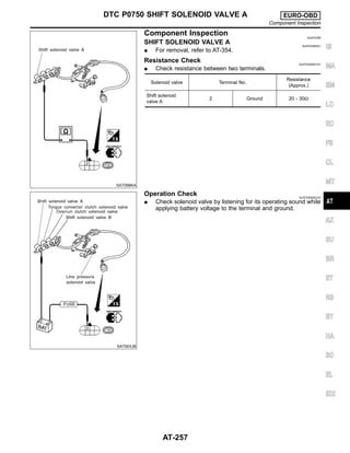
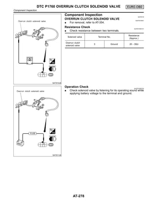
Shift solenoid A 20 - 30Ω 2
Shift solenoid B 5 - 20Ω 1
Ovr. clutch sol. 20 - 30Ω 3
Line pres. sol. 2.5 - 5Ω 4
T/conv. clutch sol. 5 - 20Ω 5
A/T Fluid Temperature Sensor NJAT0225
Monitor item Temperature Specificaiton (Approximately)
A/T fluid temperature sensor
Cold [20°C (68°F)]
"
Hot [80°C (176°F)]
1.5V
"
0.5V
2.5 kΩ
"
0.3 kΩ
Revolution Sensor NJAT0226
Condition Judgement standard
When moving at 20 km/h (12 MPH), use the CONSULT-II pulse frequency measuring
function.*1
CAUTION:
Connect the diagnosis data link cable to the vehicle diagnosis connector.
*1: A circuit tester cannot be used to test this item.
Approximately 150 Hz
When vehicle parks. Under 1.3V or over 4.5V
Dropping Resistor NJAT0227
Resistance 10 - 15Ω
SERVICE DATA AND SPECIFICATIONS (SDS)
Band Servo
AT-488](https://image.slidesharecdn.com/at-230609060207-eaf4eb52/85/at-pdf-488-320.jpg)

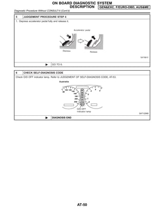
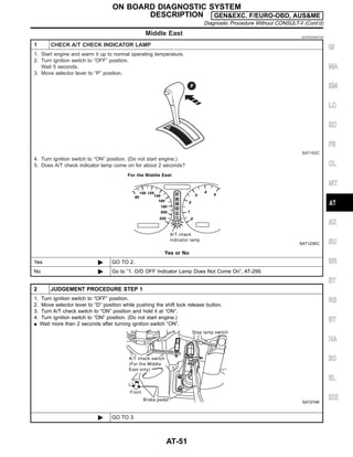
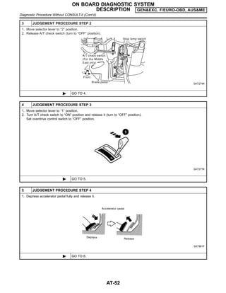
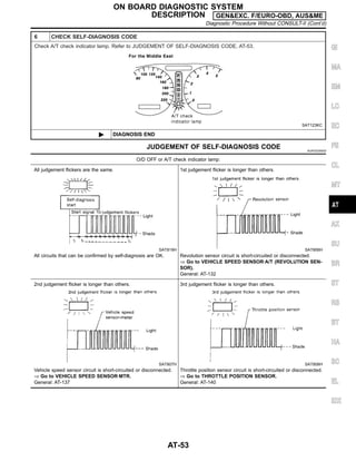
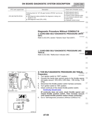
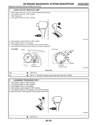
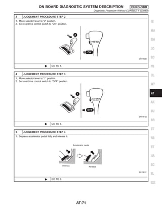
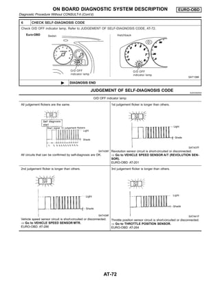
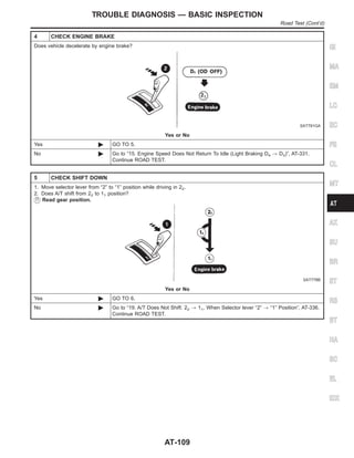
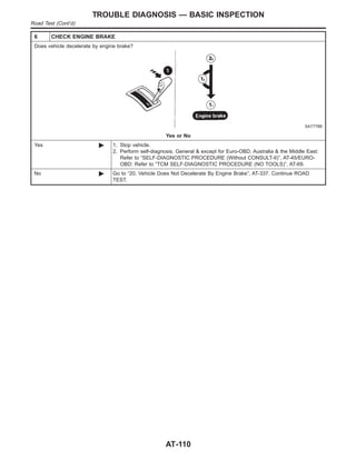
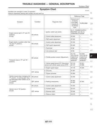
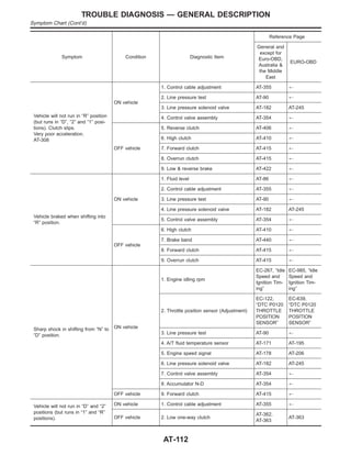
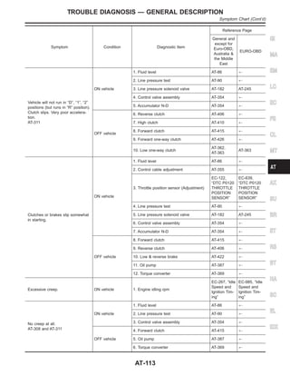
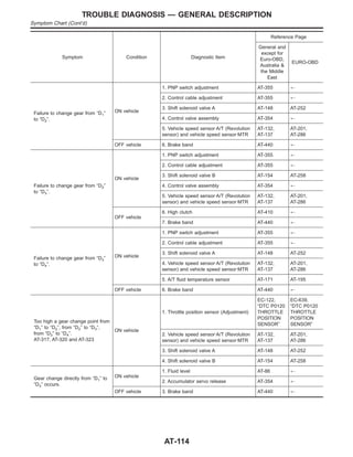
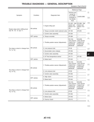
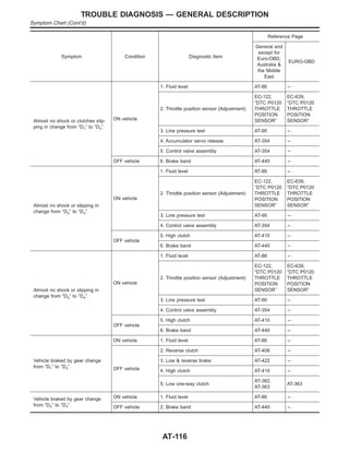
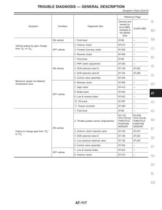
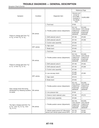
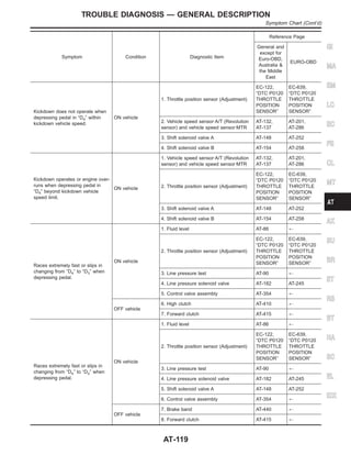
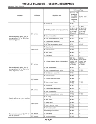
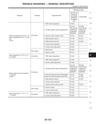
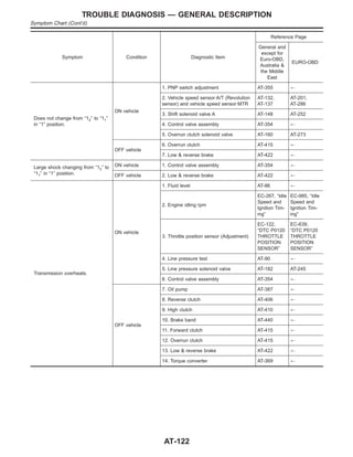
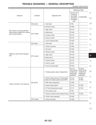
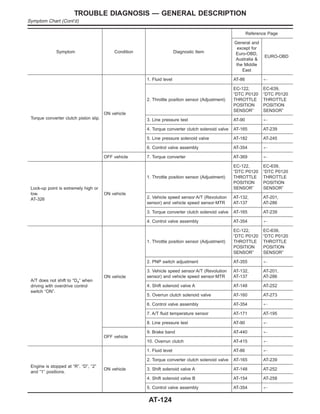
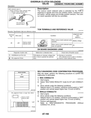
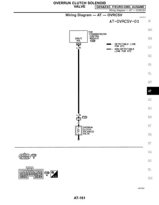
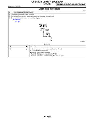
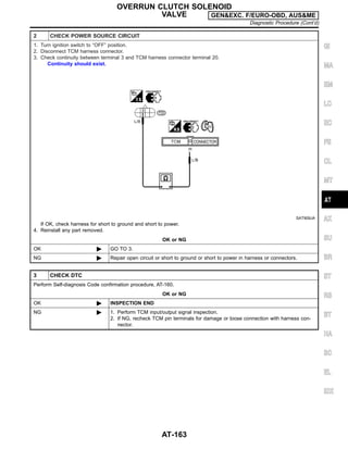
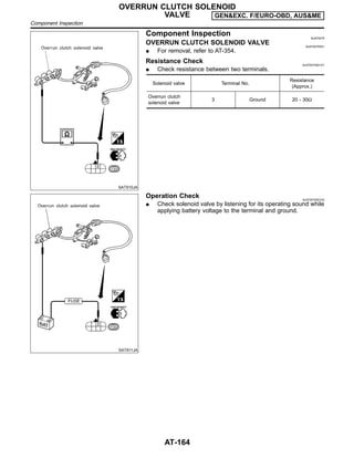
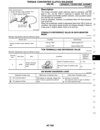
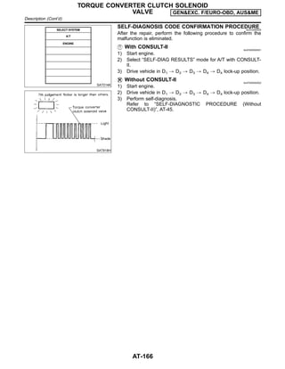
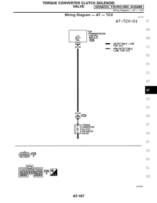
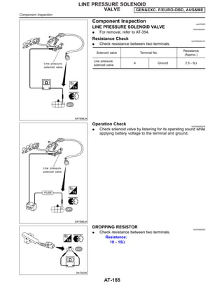
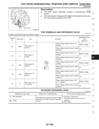
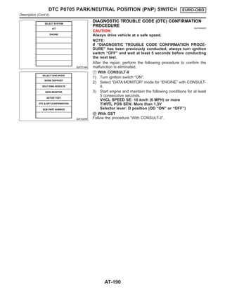
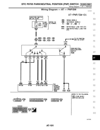
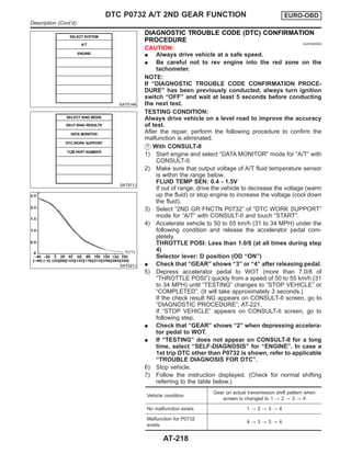
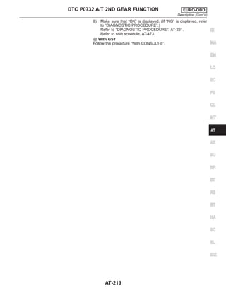
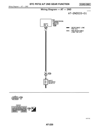
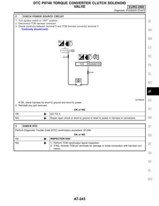
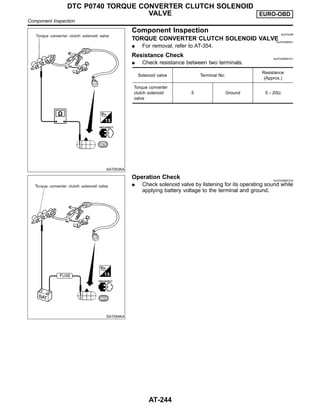
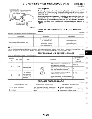
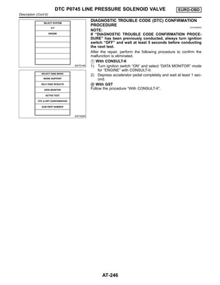
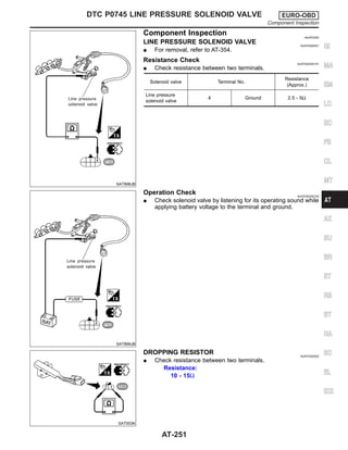
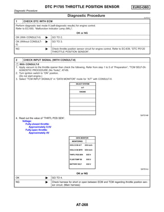
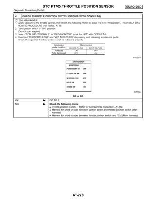
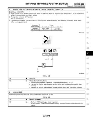
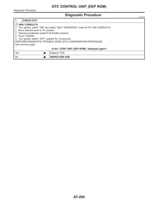
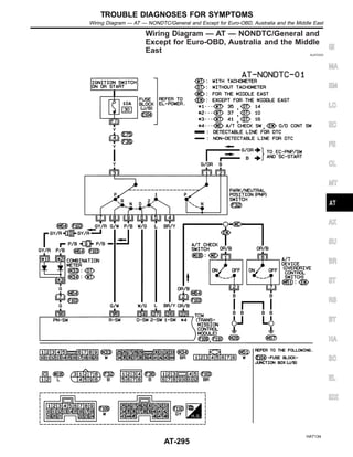
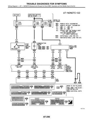
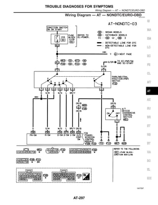
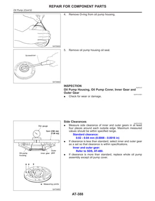
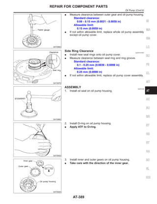
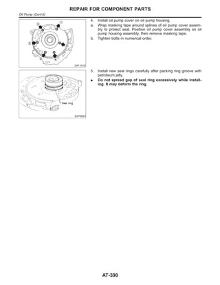
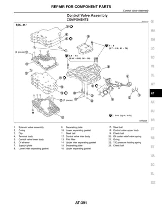
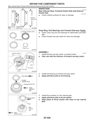
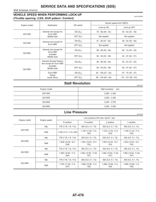
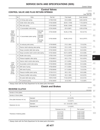
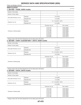
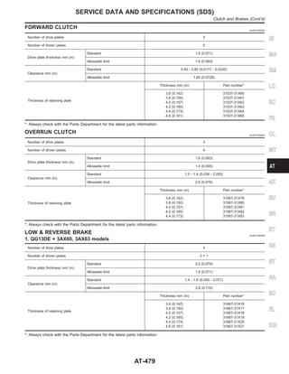
This document provides information about the automatic transmission system for certain vehicle models. It includes sections on overall system operation, control systems, diagnostic trouble codes, troubleshooting procedures, component repair, and specifications. The document contains wiring diagrams, descriptions of components and circuits, diagnostic flow charts, specifications, and repair procedures.


