
Downloaded 14 times


![40
0xlab – connect your device to application – http://0xlab.org/
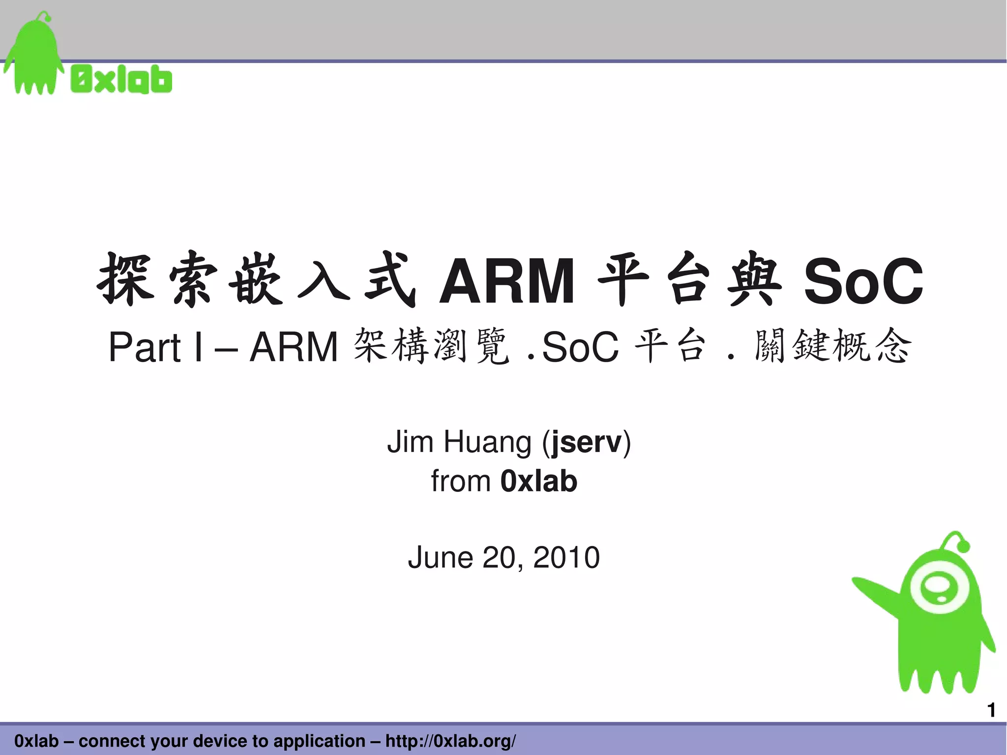
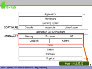
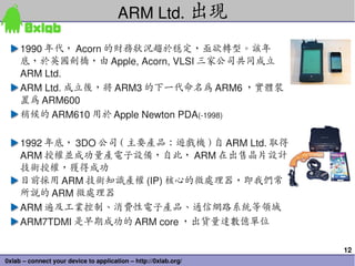
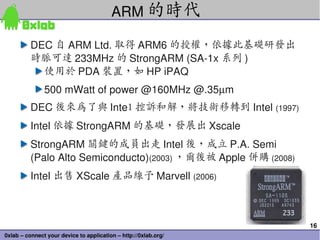
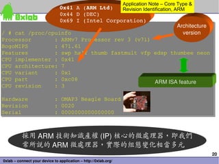
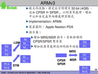
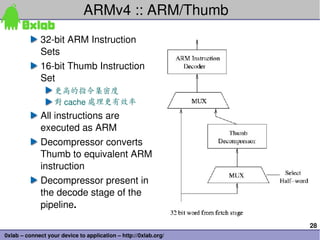
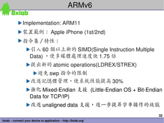
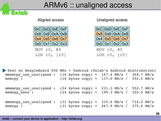
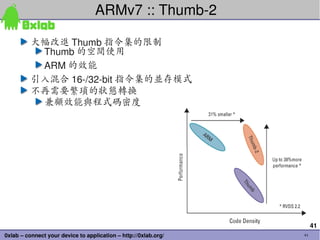
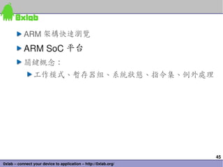
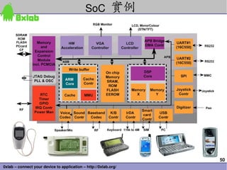
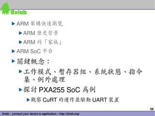
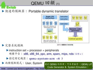
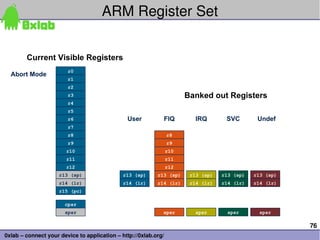
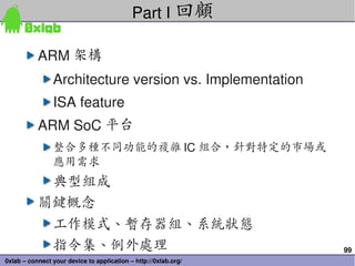
NEON Load or store 1element or 2, 3, 4elelment structure
Handle complex number, coordinates, etc.
Easy AoS to SoA
X0
Y0
Z0
X1
Y1
Z1
vld3.16 {D0, D1, D2}, [R0]!
X0X1X2X3 D0
Y0Y1Y2Y3 D1
Z0Z1Z2Z3 D2
vst3.16 {D0, D1, D2}, [R0]!
• No data swizzling needed!
• Fewer instruction, higher performance](https://image.slidesharecdn.com/arm-1-overview-090720075211-phpapp01-130509015245-phpapp02/85/Arm-1-overview-090720075211-phpapp01-40-320.jpg)
![49
0xlab – connect your device to application – http://0xlab.org/
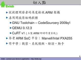
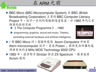
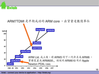
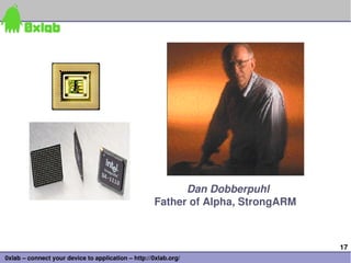
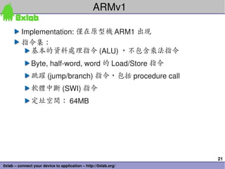
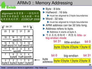
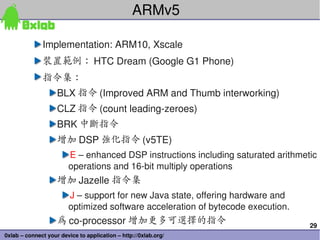
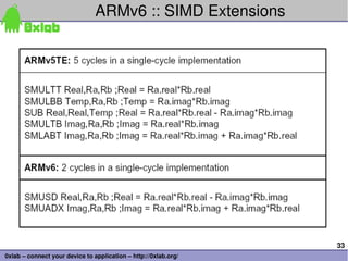
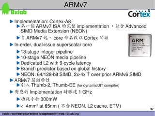
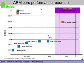
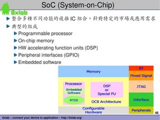
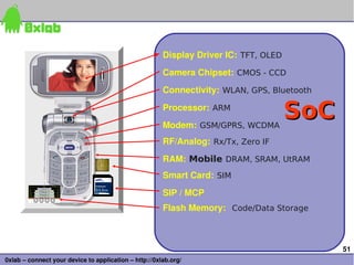
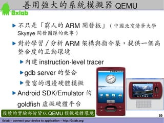
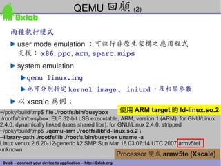
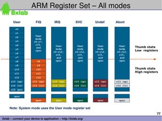
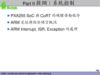
MemoryMapped I/O
R1=1234
sta r0,r1 ;; 寫入 mem address 1234
out r0,r1 ;; 寫入 I/O address 1234
Memory
0
FFFF
I/O
0
FFFF
R0=‘A’, R1=1233, R2=1234 ( 假設 1234 為 LCD 的 MMIO 位址 )
str r0, [r1,#0] ;;addr 1234 =‘A’
str r0, [r2,#0] ;;LCD 顯示‘ A’
I/O
0
1234
2345
FFFF
FDD
HD
LCD
.
.
1234
2345](https://image.slidesharecdn.com/arm-1-overview-090720075211-phpapp01-130509015245-phpapp02/85/Arm-1-overview-090720075211-phpapp01-49-320.jpg)
![66
0xlab – connect your device to application – http://0xlab.org/
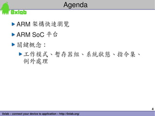
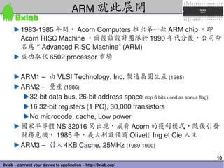
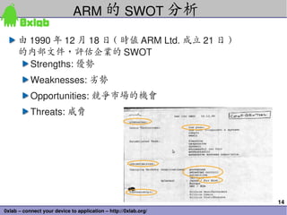
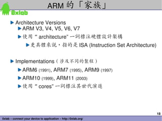
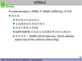
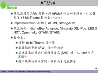
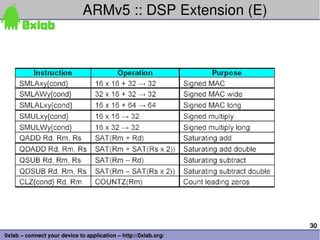
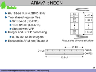
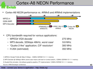
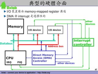
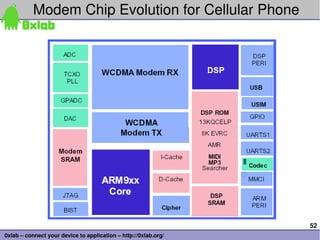
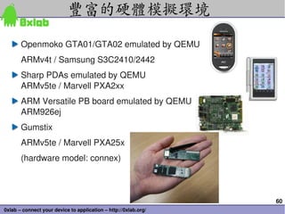
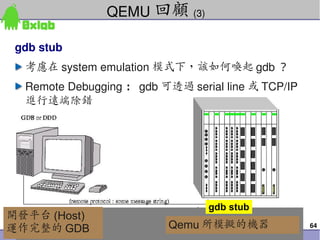
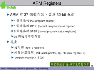
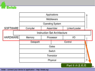
Serial / JTAG / TCP-IP
Emulated by QEMU
[PLAN] 將自製的 CuRT 作業系統運作於 PXA255 (emulated by QEMU) ,
透過 gdb stub 及 TCP/IP ,與 host 端進行 Remote debugging
# dd of=flashimage bs=1k count=16k if=/dev/zero
# dd of=flashimage bs=1k conv=notrunc if=curt_image.bin
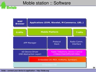
# qemusystemarm M connex pflash flashimage serial stdio s S
wait gdb connection to port 1234.
CuRT 原始程式碼: (BSD 授權 )
http://jserv.sayya.org/kernel/
CuRT 後續維護 (by cyt93cs)
http://code.google.com/p/curtv1rework/](https://image.slidesharecdn.com/arm-1-overview-090720075211-phpapp01-130509015245-phpapp02/85/Arm-1-overview-090720075211-phpapp01-66-320.jpg)
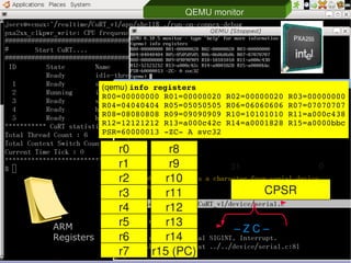

![79
0xlab – connect your device to application – http://0xlab.org/
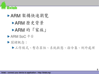
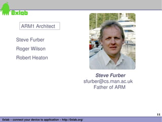
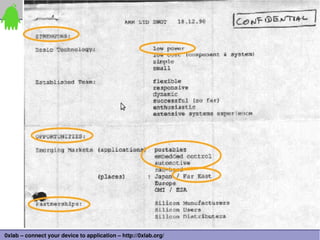
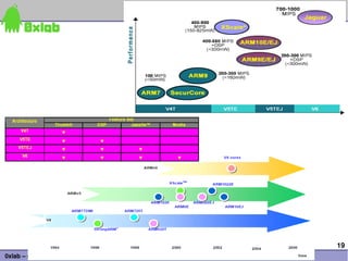
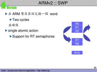
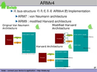
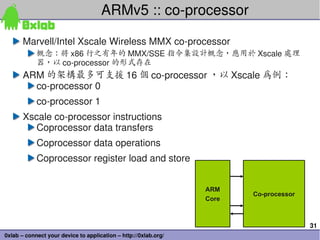
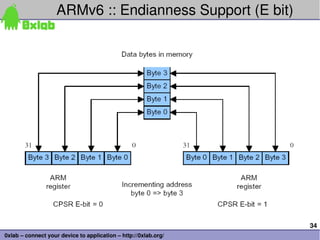
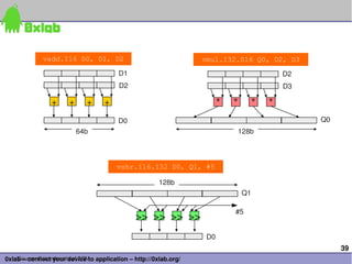
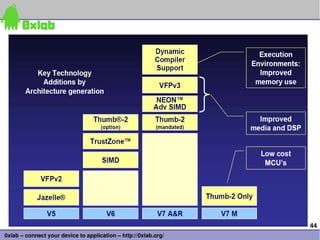
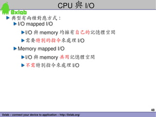
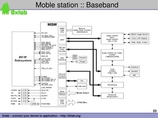
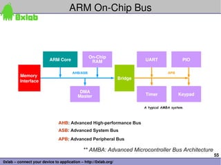
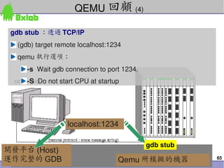
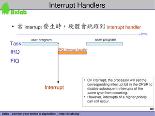
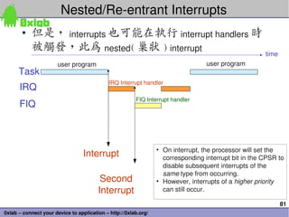
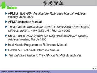
IRQ and FIQ
• Program Status Register
– 若要抑制 interrupts ,將 "F” 或 “ I” bit 設定為 1
• 一旦 interrupt 觸發,處理器將變更至 FIQ32_mode registers
或 IRQ32_mode registers
• Switch register banks
• Copies CPSR to SPSR_mode (saves mode, interrupt flags, etc.)
• Changes the CPSR mode bits (M[4:0])
• Disables interrupts
• Copies PC to R14_mode (to provide return address)
• Sets the PC to the vector address of the exception handler
N
31 30 29 28 27 … 8 7 6 5 4 3 2 1 0
Z C V I F M4 M3 M2 M1 M0](https://image.slidesharecdn.com/arm-1-overview-090720075211-phpapp01-130509015245-phpapp02/85/Arm-1-overview-090720075211-phpapp01-79-320.jpg)


![89
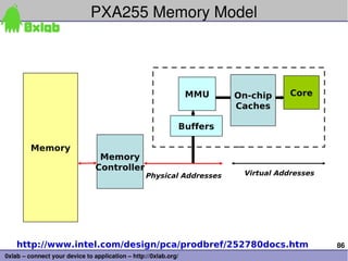
0xlab – connect your device to application – http://0xlab.org/
Serial Channel 4(CODEC)
Serial Channel 0 (USB)
Serial Channel 1
Serial Channel 2 (IrDA)
Serial Channel 3 (UART)
Power Management
Clocks, Reset and Test
JTAG
UDC-
UDC+
RXD_1
TXD_1
RXD_2
TXD_2
RXD_3
TXD_3
TXD_C
RXD_C
SCLK_C
SFRM_C
BATT_FAULT
VDD_FAULT
PWR_EN
TCK_BYP
TESTCLK
PEXTAL
PXTAL
TEXTAL
TXTAL
nRESET
nRESET_OUT
SMROM_EN
ROM_SEL
TCK
TDI
TDO
TMS
nTRST
L_DD(15:0)
L_FCLK
L_LCLK
L_PCLK
L_BIAS
GP(27:0)
GPIO PortsnCAS/ DQM(3:0)
SDCLK<2:0>
SDCKE<1:0>
nSDCAS
nSDRAS
RDY
nCS(5:0)
nWE
nOE
nRAS/ nSDCS(3:0)
LCD Control
Memory Control
RD/nWR
Transceiver Control
nPOE
nPCE<2:1>
nPIOW
nPIOR
nPWE
VDD
nIOIS16
nPWAIT
nPREG
PSKTSEL
VSS/VSSX
VDDX
PCMCIA Bus Signals
Supply
A<25:0>
D<31:0> Data Bus
Address Bus
Intelⓡ
XScale*
PXA 250
[256-pins]
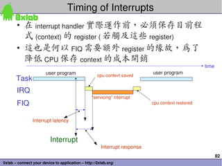
PXA255 core Function Diagram](https://image.slidesharecdn.com/arm-1-overview-090720075211-phpapp01-130509015245-phpapp02/85/Arm-1-overview-090720075211-phpapp01-89-320.jpg)
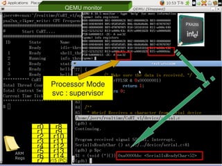
![90
0xlab – connect your device to application – http://0xlab.org/
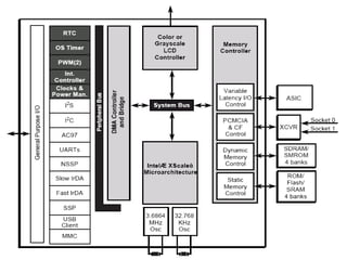
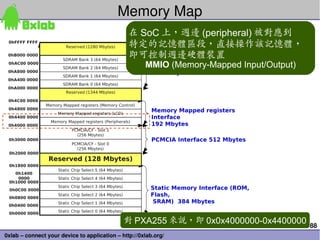
PXA255 Serial/UART
Serial Channel
4(CODEC)
Serial Channel 0
(USB)
Serial Channel
1
Serial Channel 2
(IrDA)
Serial Channel 3
(UART)
Power Management
Clocks, Reset and
Test
JTAG
UDC-
UDC+
RXD_1
TXD_1
RXD_2
TXD_2
RXD_3
TXD_3
TXD_C
RXD_C
SCLK_C
SFRM_C
BATT_FAULT
VDD_FAULT
PWR_EN
TCK_BYP
TESTCLK
PEXTAL
PXTAL
TEXTAL
TXTAL
nRESET
nRESET_OUT
SMROM_EN
ROM_SEL
TCK
TDI
TDO
TMS
nTRST
L_DD(15:0)
L_FCLK
L_LCLK
L_PCLK
L_BIAS
GP(27:0)
GPIO
Ports
nCAS/ DQM(3:0)
SDCLK<2:0>
SDCKE<1:0>
nSDCAS
nSDRAS
RDY
nCS(5:0)
nWE
nOE
nRAS/ nSDCS(3:0)
LCD Control
Memory
Control
RD/nWR
Transceiver
ControlnPOE
nPCE<2:1>
nPIOW
nPIOR
nPWE
VDD
nIOIS16
nPWAIT
nPREG
PSKTSEL
VSS/VSSX
VDDX
PCMCIA Bus
Signals
Supply
A<25:0>
D<31:0> Data
Bus
Address Bus
Intelⓡ
XScale*
PXA 250
[256-pins]
ParalleltoSerial
Converter
ParalleltoSerial
Converter
CPUCPU SerialtoParallel
Converter
SerialtoParallel
Converter
RXTX
RX TX
Computer
Terminal
Serial
Link
Universal Asynchronous Receiver/Transmitter (UART): controller](https://image.slidesharecdn.com/arm-1-overview-090720075211-phpapp01-130509015245-phpapp02/85/Arm-1-overview-090720075211-phpapp01-90-320.jpg)
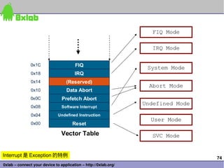
![91
0xlab – connect your device to application – http://0xlab.org/
Serial Channel
4(CODEC)
Serial Channel 0
(USB)
Serial Channel
1
Serial Channel 2
(IrDA)
Serial Channel 3
(UART)
Power Management
Clocks, Reset and
Test
JTAG
UDC-
UDC+
RXD_1
TXD_1
RXD_2
TXD_2
RXD_3
TXD_3
TXD_C
RXD_C
SCLK_C
SFRM_C
BATT_FAULT
VDD_FAULT
PWR_EN
TCK_BYP
TESTCLK
PEXTAL
PXTAL
TEXTAL
TXTAL
nRESET
nRESET_OUT
SMROM_EN
ROM_SEL
TCK
TDI
TDO
TMS
nTRST
L_DD(15:0)
L_FCLK
L_LCLK
L_PCLK
L_BIAS
GP(27:0)
GPIO
Ports
nCAS/ DQM(3:0)
SDCLK<2:0>
SDCKE<1:0>
nSDCAS
nSDRAS
RDY
nCS(5:0)
nWE
nOE
nRAS/ nSDCS(3:0)
LCD Control
Memory
Control
RD/nWR
Transceiver
ControlnPOE
nPCE<2:1>
nPIOW
nPIOR
nPWE
VDD
nIOIS16
nPWAIT
nPREG
PSKTSEL
VSS/VSSX
VDDX
PCMCIA Bus
Signals
Supply
A<25:0>
D<31:0> Data
Bus
Address Bus
Intelⓡ
XScale*
PXA 250
[256-pins]
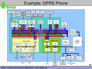
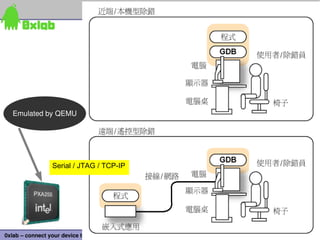
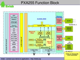
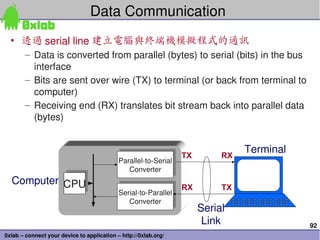
Universal Asynchronous Receiver/Transmitter
(UART): controller
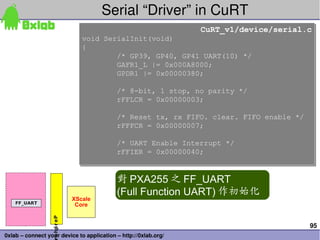
FFUART (Full function UART) 的
(memory mapped)
base address 為 0x40100000](https://image.slidesharecdn.com/arm-1-overview-090720075211-phpapp01-130509015245-phpapp02/85/Arm-1-overview-090720075211-phpapp01-91-320.jpg)
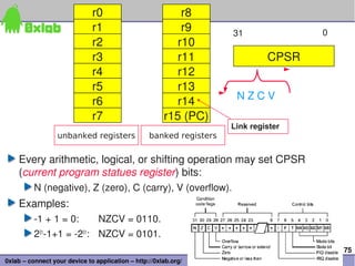
![94
0xlab – connect your device to application – http://0xlab.org/
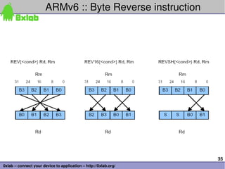
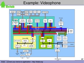
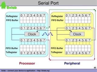
Sample shell for CuRT
CuRT_v1/app/shell/main.c
int main()
{
SerialInit();
init_interrupt_control();
init_curt();
...
shell_tid = thread_create(&shell_thread,
&thread_stk[0][THREAD_STACK_SIZE-1],
shell_thread_func,
"shell_thread",
5, NULL);
CuRT_v1/app/shell/main.c
int main()
{
SerialInit();
init_interrupt_control();
init_curt();
...
shell_tid = thread_create(&shell_thread,
&thread_stk[0][THREAD_STACK_SIZE-1],
shell_thread_func,
"shell_thread",
5, NULL);
CuRT_v1/app/shell/main.c
static void shell_thread_func(void *pdata)
{
...
char buf[80] = { '0' };
while (1) {
printf("$ ");
gets(buf);
printf("n");
...
else if (!strcmp(buf, "stat")) {
thread_resume(stat_tid);
CuRT_v1/app/shell/main.c
static void shell_thread_func(void *pdata)
{
...
char buf[80] = { '0' };
while (1) {
printf("$ ");
gets(buf);
printf("n");
...
else if (!strcmp(buf, "stat")) {
thread_resume(stat_tid);](https://image.slidesharecdn.com/arm-1-overview-090720075211-phpapp01-130509015245-phpapp02/85/Arm-1-overview-090720075211-phpapp01-94-320.jpg)
The document discusses the history and evolution of the ARM architecture. It begins with the origins of ARM at Acorn Computers in the 1980s. Key developments include the founding of ARM Ltd. in 1990 and the licensing of the ARM architecture, which led to its widespread adoption in devices. The document outlines the major ARM architecture versions and describes some of the earliest ARM processor implementations.


![Embedded Os [Linux & Co.]](https://cdn.slidesharecdn.com/ss_thumbnails/embedded-os-linux-co-1210967191310913-8-thumbnail.jpg?width=640&height=640&fit=bounds)


![[嵌入式系統] MCS-51 實驗 - 使用 IAR (3)](https://cdn.slidesharecdn.com/ss_thumbnails/mcs51iarpart3-150613071723-lva1-app6892-thumbnail.jpg?width=640&height=640&fit=bounds)


