This document provides an overview of microcontrollers and the Arduino platform. It discusses what a microcontroller is and some common types. It then introduces Arduino as an open-source prototyping platform using easy hardware and software. Several Arduino boards are described and the ATmega328p microcontroller chip is specified. The document outlines how to download the Arduino software and write programs. It provides examples of basic Arduino projects like blinking LEDs, reading sensors, and creating sounds.
![1] LED Blink
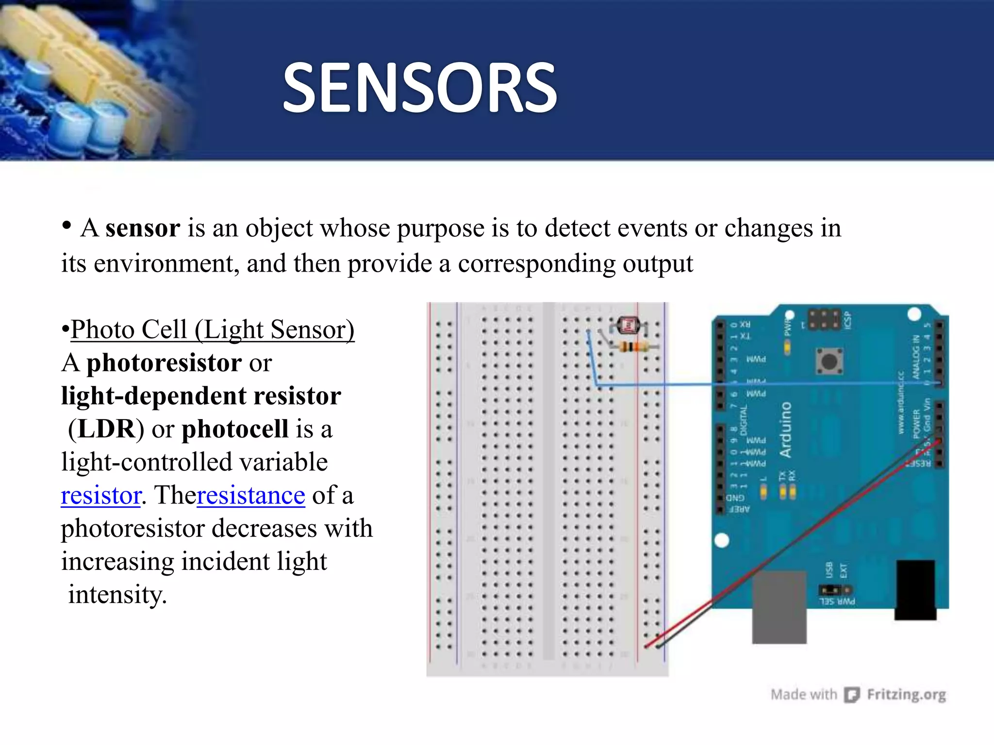
A light-emitting
diode (LED) is a two-lead
semiconductor light source.
- It is a p–n junction diode,
which emits light when
forward biased.
- A resistor is connected in
series so as to limit current
flowing through the LED.](https://image.slidesharecdn.com/arduinoworkshop-160204051621/75/Ardui-no-21-2048.jpg)
![1] Make Port line “ 9 ” as a Output and repeat the
same program
2] Reduce and increase the delay and check the
Output
3] Make Light Pattern (Reduce delay and use
loop)](https://image.slidesharecdn.com/arduinoworkshop-160204051621/75/Ardui-no-23-2048.jpg)

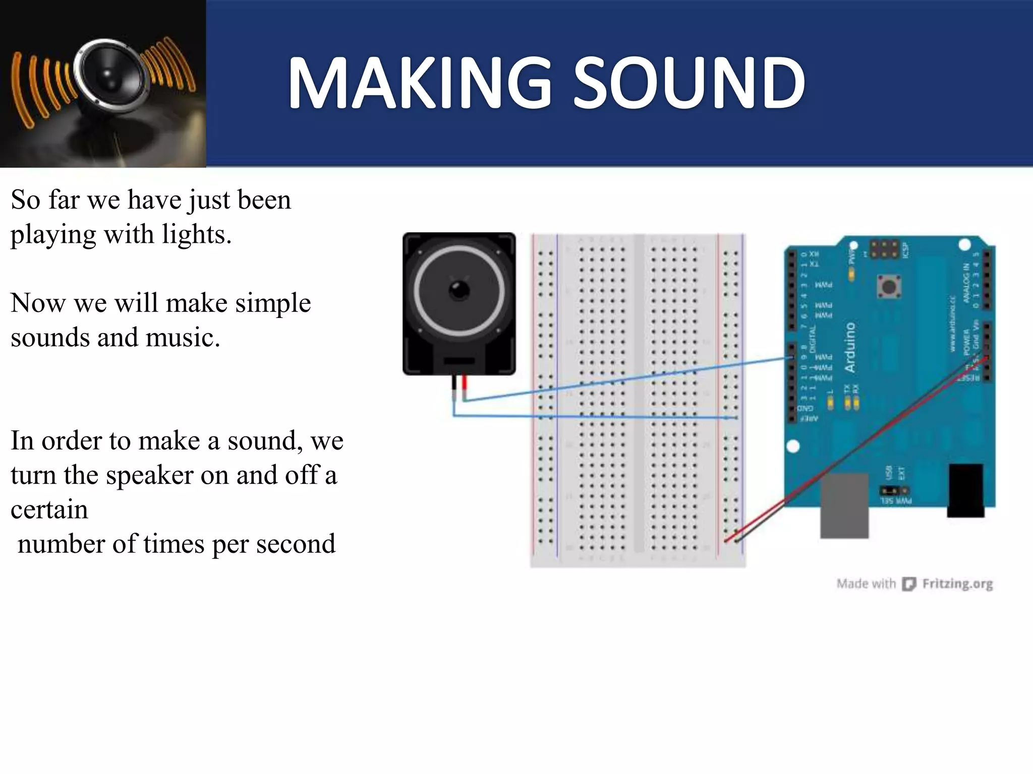
![1] Simply makes Speaker ON for some time.
2] Play some simple tone
3] Play Happy Birthday song
4] Play Song Melody
5] Playing One song Tone](https://image.slidesharecdn.com/arduinoworkshop-160204051621/75/Ardui-no-29-2048.jpg)
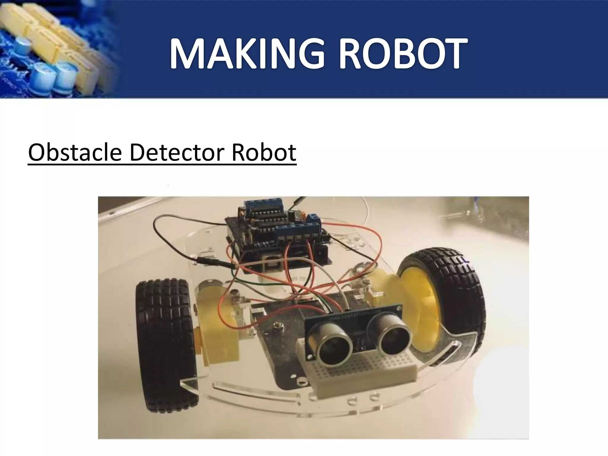
![1] Arduino
2] Motor Driver Shield
3] Ultrasonic Sensor
4] Dc Motors](https://image.slidesharecdn.com/arduinoworkshop-160204051621/75/Ardui-no-37-2048.jpg)