Download to read offline
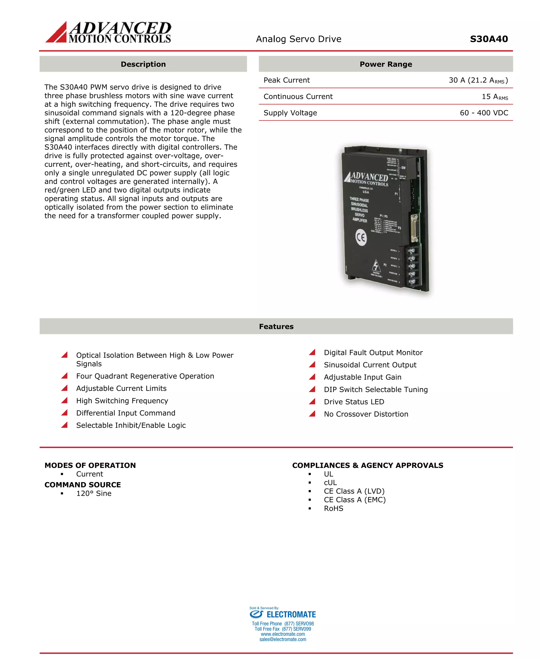
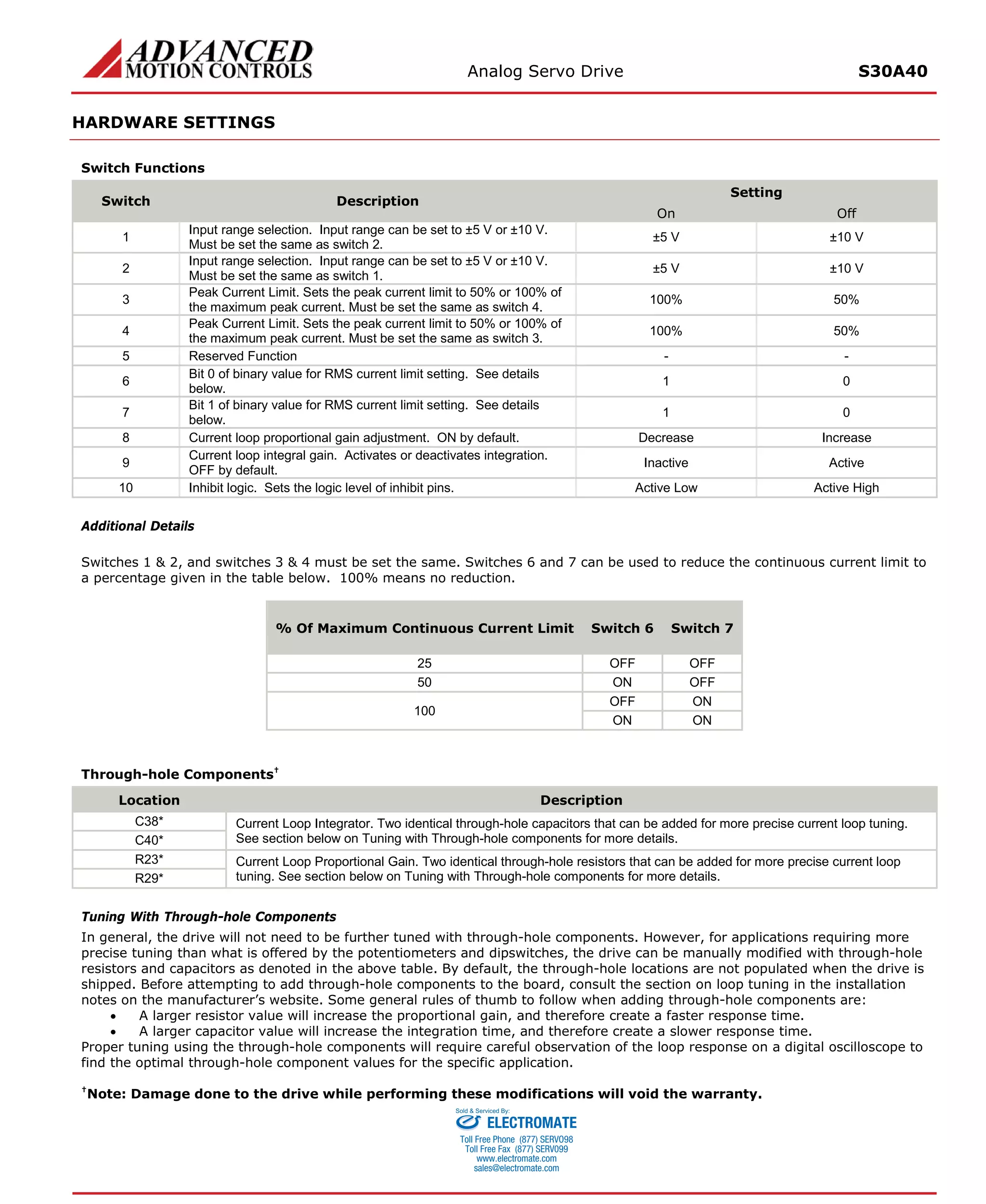

The S30A40 analog servo drive is designed to drive 3-phase brushless motors with sine wave current. It interfaces with digital controllers and requires 2 sinusoidal command signals with 120° phase shift for motor commutation. The drive provides protection against overvoltage, overcurrent and other faults. It operates from a single DC power supply and has optical isolation between high and low power signals.


![Coded Agents – with UiPath SDK + LangGraph [Virtual Hands-on Workshop]](https://cdn.slidesharecdn.com/ss_thumbnails/codedagentsdeck-251215155422-5497c599-thumbnail.jpg?width=640&height=640&fit=bounds)


