Download to read offline
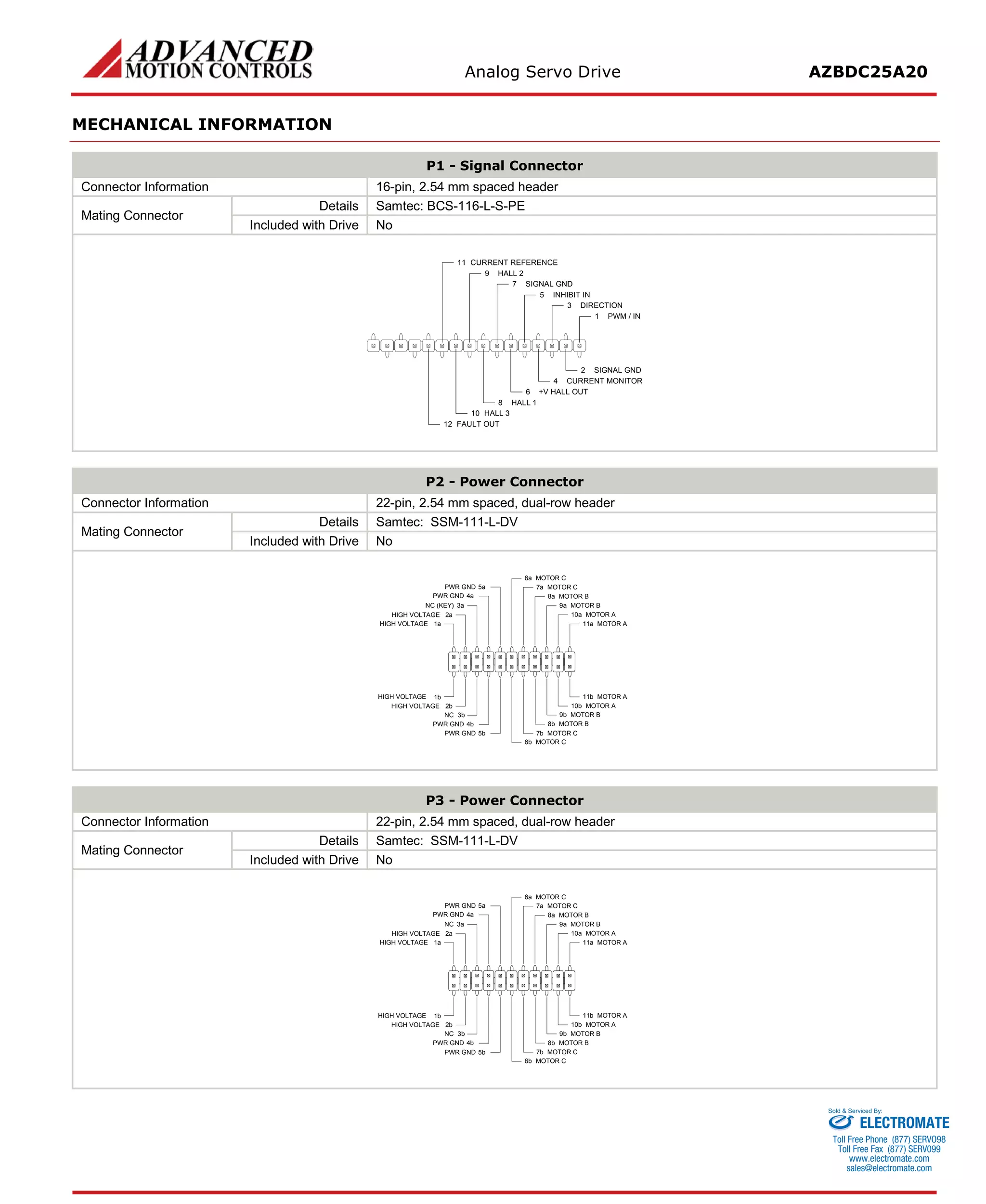

The AZBDC25A20 is a PWM servo drive designed to drive brushless and brushed DC motors. It has a peak current of 25A, continuous current of 12.5A, and operates on a supply voltage of 40-175VDC. The drive provides motor control and protection from over/under voltage, overcurrent, and overheating. It interfaces with digital controllers using PWM and direction inputs.


