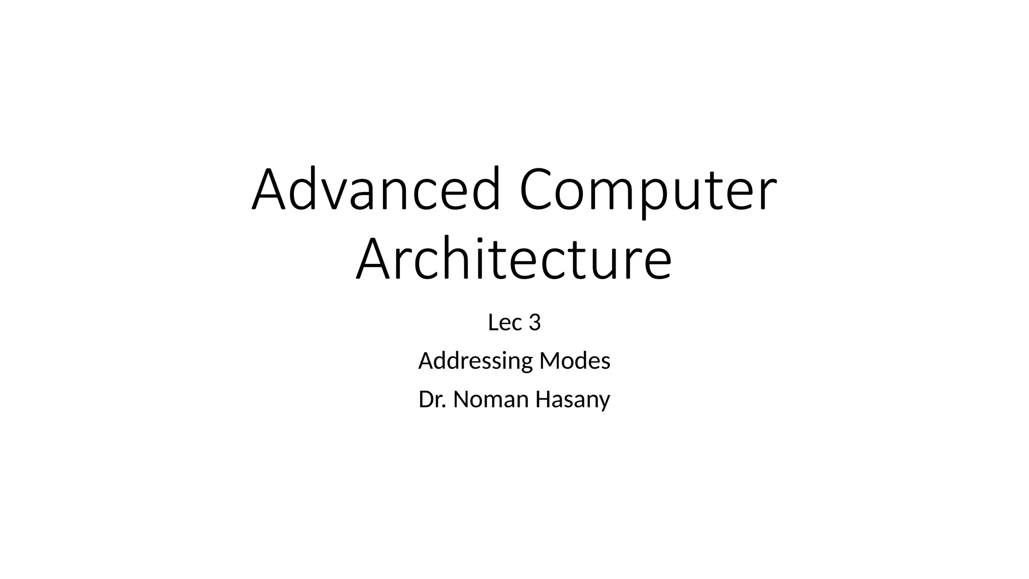
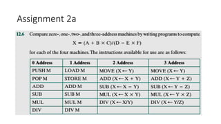
CPU with theSystem Bus
A simplified view of a processor,
indicating its connection to the
rest of the system via the
system bus.
A bus that connects major computer
components (processor, memory,
I/O) is called a system bus.
The most common computer
interconnection structures are based
on the use of one or more system
buses
3.
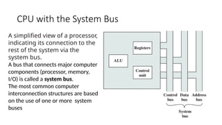
Bus Interconnection schemes
The operation of the bus is as follows. If one module wishes to send data
to
another, it must do two things: (1) obtain the use of the bus, and (2)
transfer data via the bus.
If one module wishes to request data from another module, it must (1)
obtain the use of the bus, and (2) transfer a request to the other module
over the appropriate control and address lines. It must then wait for that
second module to send the data.
4.
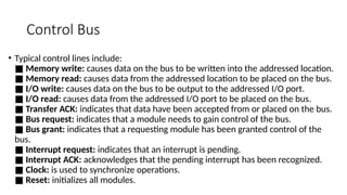
Control Bus
• Typicalcontrol lines include:
■ Memory write: causes data on the bus to be written into the addressed location.
■ Memory read: causes data from the addressed location to be placed on the bus.
■ I/O write: causes data on the bus to be output to the addressed I/O port.
■ I/O read: causes data from the addressed I/O port to be placed on the bus.
■ Transfer ACK: indicates that data have been accepted from or placed on the bus.
■ Bus request: indicates that a module needs to gain control of the bus.
■ Bus grant: indicates that a requesting module has been granted control of the
bus.
■ Interrupt request: indicates that an interrupt is pending.
■ Interrupt ACK: acknowledges that the pending interrupt has been recognized.
■ Clock: is used to synchronize operations.
■ Reset: initializes all modules.
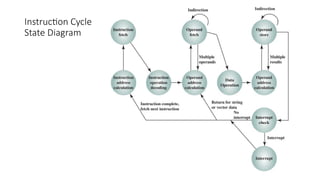
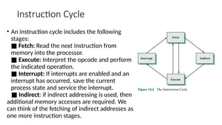
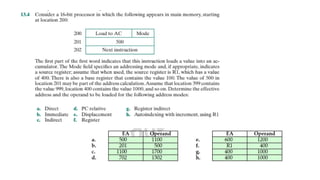
Instruction Cycle
• Aninstruction cycle includes the following
stages:
■ Fetch: Read the next instruction from
memory into the processor.
■ Execute: Interpret the opcode and perform
the indicated operation.
■ Interrupt: If interrupts are enabled and an
interrupt has occurred, save the current
process state and service the interrupt.
■ Indirect: if indirect addressing is used, then
additional memory accesses are required. We
can think of the fetching of indirect addresses as
one more instruction stages.
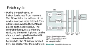
Fetch cycle
• Duringthe fetch cycle, an
instruction is read from memory.
The PC contains the address of the
next instruction to be fetched. This
address is moved to the MAR and
placed on the address bus. The
control unit requests a memory
read, and the result is placed on the
data bus and copied into the MBR
and then moved to the IR.
Meanwhile, the PC is incremented
by 1, preparatory for the next fetch.
9.
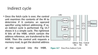
Indirect cycle
• Oncethe fetch cycle is over, the control
unit examines the contents of the IR to
determine if it contains an operand
specifier using indirect addressing. If so,
an indirect cycle is performed. Fig 14.7
shows it is a simple cycle. The rightmost
N bits of the MBR, which contain the
address reference, are transferred to the
MAR. Then the control unit requests a
memory read, to get the desired address
of the operand into the MBR.
10.
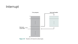
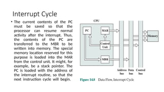
Interrupt Cycle
• Thecurrent contents of the PC
must be saved so that the
processor can resume normal
activity after the interrupt. Thus,
the contents of the PC are
transferred to the MBR to be
written into memory. The special
memory location reserved for this
purpose is loaded into the MAR
from the control unit. It might, for
example, be a stack pointer. The
PC is loaded with the address of
the interrupt routine, so that the
next instruction cycle will begin.
11.
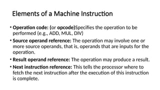
Elements of aMachine Instruction
• Operation code: (or opcode)Specifies the operation to be
performed (e.g., ADD, MUL, DIV)
• Source operand reference: The operation may involve one or
more source operands, that is, operands that are inputs for the
operation.
• Result operand reference: The operation may produce a result.
• Next instruction reference: This tells the processor where to
fetch the next instruction after the execution of this instruction
is complete.
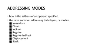
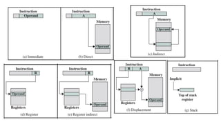
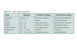
ADDRESSING MODES
• howis the address of an operand specified.
• the most common addressing techniques, or modes:
Immediate
■
Direct
■
Indirect
■
Register
■
Register indirect
■
Displacement
■
Stack
■
15.
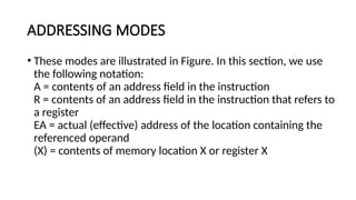
ADDRESSING MODES
• Thesemodes are illustrated in Figure. In this section, we use
the following notation:
A = contents of an address field in the instruction
R = contents of an address field in the instruction that refers to
a register
EA = actual (effective) address of the location containing the
referenced operand
(X) = contents of memory location X or register X
18.
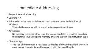
Immediate Addressing
• Simplestform of addressing
• Operand = A
• This mode can be used to define and use constants or set initial values of
variables
• Typically the number will be stored in twos complement form
• Advantage:
• No memory reference other than the instruction fetch is required to obtain
the operand, thus saving one memory or cache cycle in the instruction cycle
• Disadvantage:
• The size of the number is restricted to the size of the address field, which, in
most instruction sets, is small compared with the word length
19.
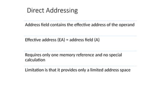
Direct Addressing
Address fieldcontains the effective address of the operand
Effective address (EA) = address field (A)
Requires only one memory reference and no special
calculation
Limitation is that it provides only a limited address space
20.
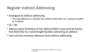
Indirect Addressing
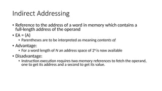
• Referenceto the address of a word in memory which contains a
full-length address of the operand
• EA = (A)
• Parentheses are to be interpreted as meaning contents of
• Advantage:
• For a word length of N an address space of 2N
is now available
• Disadvantage:
• Instruction execution requires two memory references to fetch the operand,
one to get its address and a second to get its value.
21.
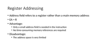
Register Addressing
• Addressfield refers to a register rather than a main memory address
• EA = R
• Advantage:
• Only a small address field is needed in the instruction
• No time-consuming memory references are required
• Disadvantage:
• The address space is very limited
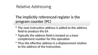
Relative Addressing
The implicitlyreferenced register is the
program counter (PC)
• The next instruction address is added to the address
field to produce the EA
• Typically the address field is treated as a twos
complement number for this operation
• Thus the effective address is a displacement relative
to the address of the instruction.
Editor's Notes
#18 The simplest form of addressing is immediate addressing, in which the operand value is present in the instruction
Operand = A
This mode can be used to define and use constants or set initial values of variables. Typically, the number will be stored in twos complement form; the leftmost bit of the operand field is used as a sign bit. When the operand is loaded into a data register, the sign bit is extended to the left to the full data word size. In some cases, the immediate binary value is interpreted as an unsigned nonnegative integer.
The advantage of immediate addressing is that no memory reference other than the instruction fetch is required to obtain the operand, thus saving one memory or cache cycle in the instruction cycle. The disadvantage is that the size of the number is restricted to the size of the address field, which, in most instruction sets, is small compared with the word length.
#19 A very simple form of addressing is direct addressing, in which the address field contains the effective address of the operand:
EA = A
The technique was common in earlier generations of computers but is not common on contemporary architectures. It requires only one memory reference and no special calculation. The obvious limitation is that it provides only a limited address space.
#20 With direct addressing, the length of the address field is usually less than the word length, thus limiting the address range. One solution is to have the address field refer to the address of a word in memory, which in turn contains a full-length address of the operand. This is known as indirect addressing:
EA = (A)
As defined earlier, the parentheses are to be interpreted as meaning contents of. The obvious advantage of this approach is that for a word length of N, an address space of 2N is now available. The disadvantage is that instruction execution requires two memory references to fetch the operand: one to get its address and a second to get its value.
Although the number of words that can be addressed is now equal to 2N, the number of different effective addresses that may be referenced at any one time is limited to 2K, where K is the length of the address field. Typically, this is not a burdensome restriction, and it can be an asset. In a virtual memory environment, all the effective address locations can be confined to page 0 of any process. Because the address field of an instruction is small, it will naturally produce low-numbered direct addresses, which would appear in page 0. (The only restriction is that the page size must be greater than or equal to 2K.) When a process is active, there will be repeated references to page 0, causing it to remain in real memory. Thus, an indirect memory reference will involve, at most, one page fault rather than two.
A rarely used variant of indirect addressing is multilevel or cascaded indirect addressing:
EA = ( . . . (A) . . . )
In this case, one bit of a full-word address is an indirect flag (I). If the I bit is 0, then the word contains the EA. If the I bit is 1, then another level of indirection is invoked. There does not appear to be any particular advantage to this approach, and its disadvantage is that three or more memory references could be required to fetch an operand.
#21 With direct addressing, the length of the address field is usually less than the word length, thus limiting the address range. One solution is to have the address field refer to the address of a word in memory, which in turn contains a full-length address of the operand. This is known as indirect addressing:
EA = (A)
As defined earlier, the parentheses are to be interpreted as meaning contents of. The obvious advantage of this approach is that for a word length of N, an address space of 2N is now available. The disadvantage is that instruction execution requires two memory references to fetch the operand: one to get its address and a second to get its value.
Although the number of words that can be addressed is now equal to 2N, the number of different effective addresses that may be referenced at any one time is limited to 2K, where K is the length of the address field. Typically, this is not a burdensome restriction, and it can be an asset. In a virtual memory environment, all the effective address locations can be confined to page 0 of any process. Because the address field of an instruction is small, it will naturally produce low-numbered direct addresses, which would appear in page 0. (The only restriction is that the page size must be greater than or equal to 2K.) When a process is active, there will be repeated references to page 0, causing it to remain in real memory. Thus, an indirect memory reference will involve, at most, one page fault rather than two.
A rarely used variant of indirect addressing is multilevel or cascaded indirect addressing:
EA = ( . . . (A) . . . )
In this case, one bit of a full-word address is an indirect flag (I). If the I bit is 0, then the word contains the EA. If the I bit is 1, then another level of indirection is invoked. There does not appear to be any particular advantage to this approach, and its disadvantage is that three or more memory references could be required to fetch an operand.
#22 Just as register addressing is analogous to direct addressing, register indirect addressing is analogous to indirect addressing. In both cases, the only difference is whether the address field refers to a memory location or a register. Thus, for register indirect address,
EA = (R)
The advantages and limitations of register indirect addressing are basically the same as for indirect addressing. In both cases, the address space limitation (limited range of addresses) of the address field is overcome by having that field refer to a word- length location containing an address. In addition, register indirect addressing uses one less memory reference than indirect addressing.
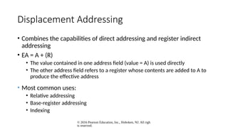
#23 A very powerful mode of addressing combines the capabilities of direct addressing and register indirect addressing. It is known by a variety of names depending on the context of its use, but the basic mechanism is the same. We will refer to this as displacement addressing:
EA = A + ( R )
Displacement addressing requires that the instruction have two address fields, at least one of which is explicit. The value contained in one address field (value = A) is used directly. The other address field, or an implicit reference based on opcode, refers to a register whose contents are added to A to produce the effective address.
We will describe three of the most common uses of displacement addressing:
• Relative addressing
• Base-register addressing
• Indexing
#24 For relative addressing, also called PC-relative addressing, the implicitly referenced register is the program counter (PC). That is, the next instruction address is added to the address field to produce the EA. Typically, the address field is treated as a twos complement number for this operation. Thus, the effective address is a displacement relative to the address of the instruction.
Relative addressing exploits the concept of locality that was discussed in Chapters 4 and 8. If most memory references are relatively near to the instruction being executed, then the use of relative addressing saves address bits in the instruction.