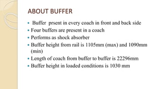
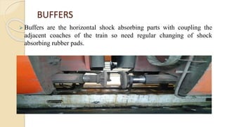
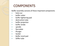
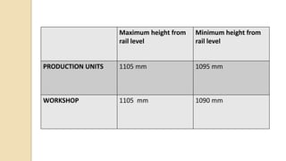
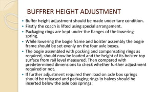
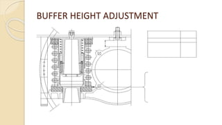
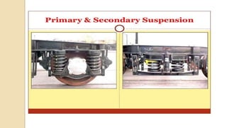
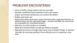
PROJECT REVIEW
ANALYSIS OF BUFFER IN COACHES
SUBMITED BY:-
RITESH ROHAN
BE/6258/11
OBJECTIVE
 Indispensible need for proper maintenance of buffer
and bolster assembly to improve shock absorbing
capacity of coaches to provide safety and comfort to the
passengers travelling . It is necessary that correct
practices are followed and other maintenance
schedules , so that it works efficiently and give trouble
free service on time.
INTRODUCTION
 Indian railways was first introduced in 1853 with a stretch of 34 km from
Bombay to Thane.
 IR operates both long distance and suburban rail systems on a multi-gauge
network of broad, metre and narrow gauges.
 Indian Railways manufactures much of its heavy engineering components
at its six manufacturing plants, called Production Units, which are managed
directly by the Ministry. Popular production units are CLW and DLW for
electric and diesel locomotives; ICF and RCF for passenger coaches .
 Each of these production units is headed by a general manager, who also
reports directly to the Railway Board.
DANAPUR DIVISION
 Danapur divison was formed on 1925
 The eastern railway was formed on 14.04.1952 and
Danapur division came under the control of eastern
railway. It came under the control of east central railway
w.e.f 01.10.2002.
 Danapur division is being an integral part of ECR is well
renowned for maintainance practices for ICF coaches.
MAINTENANCE
 Intermediate overhauling(IOH): 9 months or 2 lakh km
 Periodic overhauling(POH): 18 months or 4 lakh km
 Maintenance schedules:-
 Schedule A (1 month ± 3 days): can be done on washing line
when needed can be sent to sick line
 Schedule B (3 month ± 7 days): can be done on washing line
when needed can be sent to sick line
 Schedule C (6 month ± 15 days): can only be done on sick line
ABOUT BUFFER
 Buffer prsent in every coach in front and back side
 Four buffers are present in a coach
 Performs as shock absorber
 Buffer height from rail is 1105mm (max) and 1090mm
(min)
 Length of coach from buffer to buffer is 22296mm
 Buffer height in loaded conditions is 1030 mm
 Buffers are the horizontal shock absorbing parts with coupling the
adjacent coaches of the train so need regular changing of shock
absorbing rubber pads.
BUFFERS
COMPONENTS
Buffer assembly consists of these important components
 helix nut
 buffer cotter
 buffer tightening pad
 destruction tube
 buffer projection
 buffer stroke
 spindle
 face plate
 Plunger
 Socket
 Buffer recoil pad
 Stiffer tube
Maximum height from
rail level
Minimum height from
rail level
PRODUCTION UNITS 1105 mm 1095 mm
WORKSHOP 1105 mm 1090 mm
BUFFRER HEIGHT ADJUSTMENT
 Buffer height adjustment should be made under tare condition.
 Firstly the coach is lifted using special arrangement.
 Packaging rings are kept under the flanges of the lowering
spring.
 While lowering the bogie frame and bolster assembly the bogie
frame should be set evenly on the four axle boxes.
 The bogie assembled with packing and compensating rings as
required, should now be loaded and the height of its bolster top
surface from rail level measured. Then compared with
predetermined dimensions to check whether further adjustment
required or not.
 If further adjustment required then load on axle box springs
should be released and packaging rings in halves should be
inserted below the axle box springs.
BUFFER HEIGHT ADJUSTMENT
PROBLEMS ENCOUNTERED
 Cases of buffer casing /socket crack are very high
Remedy: insufficient heat treatment is the main reason
proper and timely maintenance can remove this defect
 Rubber pad wears out
Reject pads which show tears, large material chunks, large bond failures, or
extreme wear into the steel plate edges. . Creases and folds are normal and
are acceptable for reconditioned gears.
 Split pins are either broken or corroded
Nyloc Nut instead of Bolt-nut-split pin fitted on Coaches.
 Repeated occurrence of bogie side frame crack at bottom flange in axle box
Remedy: By removing welding of heat affected zone at suspension strap
area.
THANK YOU

A project on buffer

  • 1.
    PROJECT REVIEW ANALYSIS OFBUFFER IN COACHES SUBMITED BY:- RITESH ROHAN BE/6258/11
  • 2.
    OBJECTIVE  Indispensible needfor proper maintenance of buffer and bolster assembly to improve shock absorbing capacity of coaches to provide safety and comfort to the passengers travelling . It is necessary that correct practices are followed and other maintenance schedules , so that it works efficiently and give trouble free service on time.
  • 3.
    INTRODUCTION  Indian railwayswas first introduced in 1853 with a stretch of 34 km from Bombay to Thane.  IR operates both long distance and suburban rail systems on a multi-gauge network of broad, metre and narrow gauges.  Indian Railways manufactures much of its heavy engineering components at its six manufacturing plants, called Production Units, which are managed directly by the Ministry. Popular production units are CLW and DLW for electric and diesel locomotives; ICF and RCF for passenger coaches .  Each of these production units is headed by a general manager, who also reports directly to the Railway Board.
  • 4.
    DANAPUR DIVISION  Danapurdivison was formed on 1925  The eastern railway was formed on 14.04.1952 and Danapur division came under the control of eastern railway. It came under the control of east central railway w.e.f 01.10.2002.  Danapur division is being an integral part of ECR is well renowned for maintainance practices for ICF coaches.
  • 5.
    MAINTENANCE  Intermediate overhauling(IOH):9 months or 2 lakh km  Periodic overhauling(POH): 18 months or 4 lakh km  Maintenance schedules:-  Schedule A (1 month ± 3 days): can be done on washing line when needed can be sent to sick line  Schedule B (3 month ± 7 days): can be done on washing line when needed can be sent to sick line  Schedule C (6 month ± 15 days): can only be done on sick line
  • 6.
    ABOUT BUFFER  Bufferprsent in every coach in front and back side  Four buffers are present in a coach  Performs as shock absorber  Buffer height from rail is 1105mm (max) and 1090mm (min)  Length of coach from buffer to buffer is 22296mm  Buffer height in loaded conditions is 1030 mm
  • 7.
     Buffers arethe horizontal shock absorbing parts with coupling the adjacent coaches of the train so need regular changing of shock absorbing rubber pads. BUFFERS
  • 8.
    COMPONENTS Buffer assembly consistsof these important components  helix nut  buffer cotter  buffer tightening pad  destruction tube  buffer projection  buffer stroke  spindle  face plate  Plunger  Socket  Buffer recoil pad  Stiffer tube
  • 9.
    Maximum height from raillevel Minimum height from rail level PRODUCTION UNITS 1105 mm 1095 mm WORKSHOP 1105 mm 1090 mm
  • 10.
    BUFFRER HEIGHT ADJUSTMENT Buffer height adjustment should be made under tare condition.  Firstly the coach is lifted using special arrangement.  Packaging rings are kept under the flanges of the lowering spring.  While lowering the bogie frame and bolster assembly the bogie frame should be set evenly on the four axle boxes.  The bogie assembled with packing and compensating rings as required, should now be loaded and the height of its bolster top surface from rail level measured. Then compared with predetermined dimensions to check whether further adjustment required or not.  If further adjustment required then load on axle box springs should be released and packaging rings in halves should be inserted below the axle box springs.
  • 11.
  • 13.
    PROBLEMS ENCOUNTERED  Casesof buffer casing /socket crack are very high Remedy: insufficient heat treatment is the main reason proper and timely maintenance can remove this defect  Rubber pad wears out Reject pads which show tears, large material chunks, large bond failures, or extreme wear into the steel plate edges. . Creases and folds are normal and are acceptable for reconditioned gears.  Split pins are either broken or corroded Nyloc Nut instead of Bolt-nut-split pin fitted on Coaches.  Repeated occurrence of bogie side frame crack at bottom flange in axle box Remedy: By removing welding of heat affected zone at suspension strap area.
  • 14.