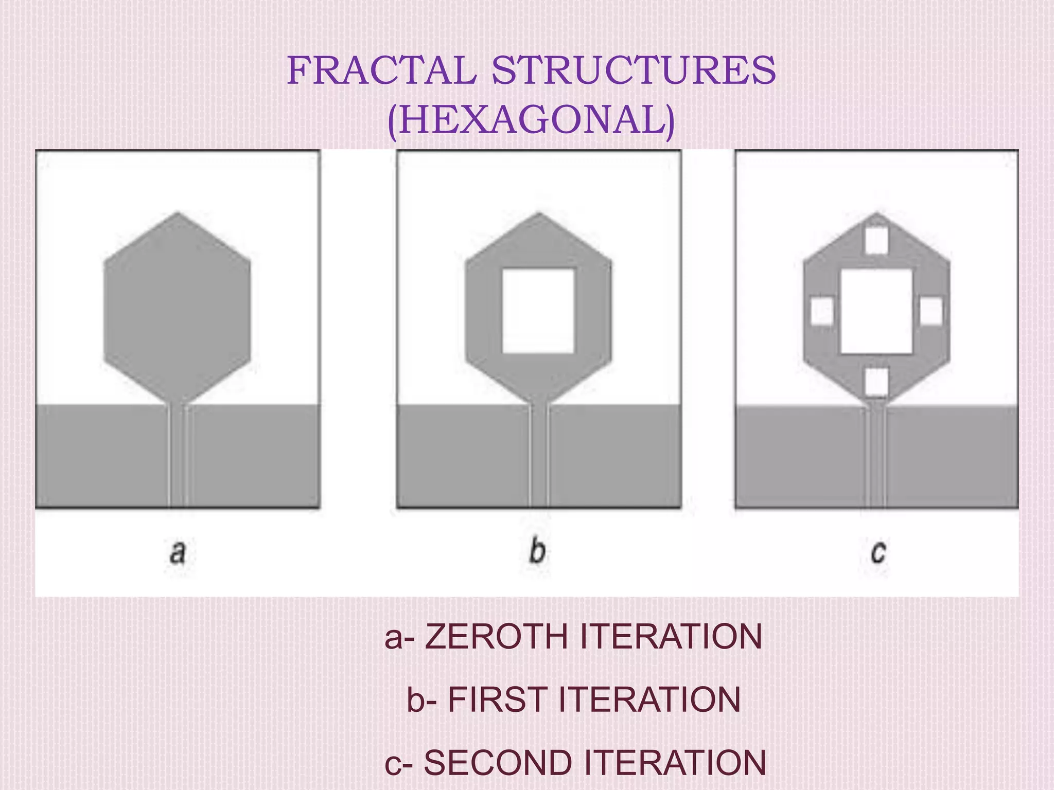
CPW – FED HEXAGONAL
SIERPINSKI SUPER WIDE
BAND FRACTAL ANTENNA
By: R.Sreekar
151fa05047
Guide: N.Srikanth
CONTENTS:
•INTRODUCTION
•EXPLANATION OF BASIC TERMS
•ANTENNA DESIGN
•FRACTIONING OF ANTENNA
•PERFORMANCE PARAMETERS
•ADVANTAGES
•APPLICATIONS
•CONCLUSION
WHAT IS AN ANTENNA?
 Antennas act as both transmitters and as receivers
of information where the information in electrical form is
converted into the electro magnetic form or radio waves.
 These are later received and the reverse process
takes place and the information can be gathered. This is
helpful for wireless transmission.
 But in today's world every electronic device has
reduced it’s size to a large extent. So there is a need to
reduce the size of the antenna.
 But if we reduce the size of the antenna the
bandwidth and efficiency will also reduce since the size
of antenna is proportional to one fourth of wavelength of
transmitted wave.
Length of antenna = wavelength/4
= C/4*f
where c= velocity of light and
f= frequency of transmitted wave
BASIC TERMS
FRACTIONING:
To avoid this problem we need fractioning of
antenna. It means, the shape of the antenna is changed or
fractioned into parts of other forms. For example an
antenna of hexagonal shape fractioned with square shape.
CPW-FED:
coplanar wave guide is an electrical
transmission line which acts as a feeding to convert signal
to radio waves. It has a conducting path fitted on to a
dielectric substrate with a pair of return conductors held in
parallel, hence called coplanar.
This wave guide also helps in distortion less transmission. It acts
as a barrel of a gun which restricts the expansion of hot gases
providing speed to the bullet. Just like that the wave guide plays
an important role in an antenna. Feeding also helps at the
receiver side for the conversion of radio waves to the electrical
waves.
But cpw-feeding is preferred most as it provides more band
width when compared to other feeds. Even it provides better
impedance matching for max. power transfer. .
ANTENNA DESIGN
 This antenna structure consists of a hexagonal radiator
loaded with two iterations of square slot to form the hexagonal
Sierpinski radiator, coplanar waveguide feed line and partial
rectangular ground planes.
 The reason behind using the hexagonal radiator is that the
bandwidth performance of a circular patch antenna is better in
comparison with any other geometry and hexagonal geometry is
approximately equal to that of circular patch.
 Coplanar waveguide feeding technique is utilized due
to its several advantages of coplanar nature, ease of
fabrication, less losses etc…
FRACTIONING OF ANTENNA
 The basic or zeroth iteration of the designed antenna
structure consists of a hexagonal radiator, coplanar waveguide
feeding and partial rectangular ground planes symmetrical to the
feed line.
 This hexagonal radiator is loaded with a rectangular slot
due to the fact that the current density is concentrated along the
periphery of the radiator and zero or negligible current is present
at the central portion.
 So removal of this zero current density portion does not
affect the antenna performance. This slot loading resulted into first
SIERPINSKI
It is a name given to the structures which are self similar to each
other and are divided into many parts of that particular shape.
Consider sierpinski triangle, which has similar type of equilateral
triangles with in itself repeatedly constructed to form a mesh like
structure as shown.
Initially they are in the form of a may be a triangle, rectangle,
square, e.t.c.. But the distribution of current is not present at
the center of the structure as it is concentrated along the
transmission line. So the part of same or a different structure
with sides less than the previous structure must be cut to form
a fractal structure. The formation of fractals is as shown.
FRACTAL STRUCTURES
(HEXAGONAL)
a- ZEROTH ITERATION
b- FIRST ITERATION
c- SECOND ITERATION
REFLECTION CO EFFICIENT:
A parameter that describes how much
of an electro magnetic wave is reflected by an impedance
discontinuity in the transmission medium. It is equal to the ratio of
the amplitude of the reflected wave to the incident wave.
RESONATING FREQUENCY:
The design expression of simple
circular micro strip antenna for calculating the resonant frequency
is given as,
where v0 is the velocity of the light
FREQUENCY VS REFLECTION CO EFFICIENT
HFSS
(High frequency electro magnetic field simulation)
 It an essential tool for engineers tasked with
executing accurate and rapid design in high-frequency
and high-speed electronic devices and platforms.
 This technology is based on finite element, integral
equation, and asymptotic and advanced hybrid methods
to solve a wide range of applications.
 In HFSS the analysis is carried out by dividing the
frequency spectrum into multiple parts.
 Basic performance characterization such as return loss,
input impedance, gain, directivity and a variety of polarization
characteristics can be analyzed in HFSS.
Dimension Value (mm) Dimension Value (mm)
Lsub 30 Wsub 28
Lg 8.5 Wg 13
g 0.1 Wf 1.4
T 0.3 a 8.3
b 7.19 c 2.4
PERFORMANCE PARAMETERS
There must be a way to describe how effectively an antenna
works. This can be done by using performance parameters.
There are 3 such parameters:
Peak power gain
Radiation efficiency
Total efficiency
The peak gain describes how well an antenna is able to
convert input power to radio waves during transmission and
the converse during receiving.
If the radiated equation of an antenna is given by U, then the peak
value of radiated intensity is given as Umax . The total radiated
power can be found by integrating the equation U. The equation
for gain is given as:
G = Eantenna * D
Where D is the directivity of the antenna. i.e..
D= 4∏*(Umax ∕ prad)
Radiation efficiency is defined as the ratio of radiated power to the
input power of an antenna, without considering the losses.
Similarly the total efficiency is the efficiency of an antenna
with consideration of losses like:
(a) Reflections because of the mismatch between the
transmission line and the antenna and
(b) I2R losses (conduction and dielectric).
Where ML is the mismatch loss of the antenna. The value of
total efficiency is always less than or equal to radiation
efficiency due to the value of ML which lies between 0 and 1.
For no loss, the value of ML is 1.
ADVANTAGES
 Size of the resultant antenna is compact
 Can be applicable for Super Wide Band and Ultra Wide
Band applications.
 The designed antenna configurations cover frequency
spectrum from 0.7969 to 17.4663 GHz and 2.6569 to 10.6948
GHz with dimensions of 135 × 90 and 39.5 × 36.9 mm2.
 Since it has variable band width, they can be used for
both short range and long range communications.
APPLICATIONS
Owing to the advantages of miniaturized size and wide
bandwidth over other antenna structures, this antenna
structure will be useful for
UWB and mobile applications,
Wireless access systems - (17.1–17.3 GHz)
Defense systems, broadband disaster relief applications
(BBDR) (4.94–4.99 GHz)
 Radio determination applications - (4.5–7 GHz, 13.4–14
GHz)
Industrial, scientific and medical (ISM) (24.25 GHz)
Wideband high definition television
Aeronautical radio navigation
We can use this fractioned antenna for various applications by
varying the dimensions of the antenna and even feeding.
CONCLUSION
The cpw-fed hexagonal sierpinski super wide
band fractal antenna can be used for SWB and
UWB applications and the size of antenna has
been reduced to a large extent with wider
applications, and the bandwidth can be
enhanced in a way to be useful for many other
applications.
Thank
you
Sreekar
151fa05047

A glimpse of fractal antenna design

  • 1.
    CPW – FEDHEXAGONAL SIERPINSKI SUPER WIDE BAND FRACTAL ANTENNA By: R.Sreekar 151fa05047 Guide: N.Srikanth
  • 2.
    CONTENTS: •INTRODUCTION •EXPLANATION OF BASICTERMS •ANTENNA DESIGN •FRACTIONING OF ANTENNA •PERFORMANCE PARAMETERS •ADVANTAGES •APPLICATIONS •CONCLUSION
  • 3.
    WHAT IS ANANTENNA?  Antennas act as both transmitters and as receivers of information where the information in electrical form is converted into the electro magnetic form or radio waves.  These are later received and the reverse process takes place and the information can be gathered. This is helpful for wireless transmission.  But in today's world every electronic device has reduced it’s size to a large extent. So there is a need to reduce the size of the antenna.
  • 4.
     But ifwe reduce the size of the antenna the bandwidth and efficiency will also reduce since the size of antenna is proportional to one fourth of wavelength of transmitted wave. Length of antenna = wavelength/4 = C/4*f where c= velocity of light and f= frequency of transmitted wave
  • 5.
    BASIC TERMS FRACTIONING: To avoidthis problem we need fractioning of antenna. It means, the shape of the antenna is changed or fractioned into parts of other forms. For example an antenna of hexagonal shape fractioned with square shape. CPW-FED: coplanar wave guide is an electrical transmission line which acts as a feeding to convert signal to radio waves. It has a conducting path fitted on to a
  • 6.
    dielectric substrate witha pair of return conductors held in parallel, hence called coplanar.
  • 7.
    This wave guidealso helps in distortion less transmission. It acts as a barrel of a gun which restricts the expansion of hot gases providing speed to the bullet. Just like that the wave guide plays an important role in an antenna. Feeding also helps at the receiver side for the conversion of radio waves to the electrical waves. But cpw-feeding is preferred most as it provides more band width when compared to other feeds. Even it provides better impedance matching for max. power transfer. .
  • 8.
    ANTENNA DESIGN  Thisantenna structure consists of a hexagonal radiator loaded with two iterations of square slot to form the hexagonal Sierpinski radiator, coplanar waveguide feed line and partial rectangular ground planes.  The reason behind using the hexagonal radiator is that the bandwidth performance of a circular patch antenna is better in comparison with any other geometry and hexagonal geometry is approximately equal to that of circular patch.
  • 9.
     Coplanar waveguidefeeding technique is utilized due to its several advantages of coplanar nature, ease of fabrication, less losses etc…
  • 10.
    FRACTIONING OF ANTENNA The basic or zeroth iteration of the designed antenna structure consists of a hexagonal radiator, coplanar waveguide feeding and partial rectangular ground planes symmetrical to the feed line.  This hexagonal radiator is loaded with a rectangular slot due to the fact that the current density is concentrated along the periphery of the radiator and zero or negligible current is present at the central portion.  So removal of this zero current density portion does not affect the antenna performance. This slot loading resulted into first
  • 11.
    SIERPINSKI It is aname given to the structures which are self similar to each other and are divided into many parts of that particular shape. Consider sierpinski triangle, which has similar type of equilateral triangles with in itself repeatedly constructed to form a mesh like structure as shown.
  • 12.
    Initially they arein the form of a may be a triangle, rectangle, square, e.t.c.. But the distribution of current is not present at the center of the structure as it is concentrated along the transmission line. So the part of same or a different structure with sides less than the previous structure must be cut to form a fractal structure. The formation of fractals is as shown.
  • 13.
    FRACTAL STRUCTURES (HEXAGONAL) a- ZEROTHITERATION b- FIRST ITERATION c- SECOND ITERATION
  • 14.
    REFLECTION CO EFFICIENT: Aparameter that describes how much of an electro magnetic wave is reflected by an impedance discontinuity in the transmission medium. It is equal to the ratio of the amplitude of the reflected wave to the incident wave. RESONATING FREQUENCY: The design expression of simple circular micro strip antenna for calculating the resonant frequency is given as, where v0 is the velocity of the light
  • 15.
  • 16.
    HFSS (High frequency electromagnetic field simulation)  It an essential tool for engineers tasked with executing accurate and rapid design in high-frequency and high-speed electronic devices and platforms.  This technology is based on finite element, integral equation, and asymptotic and advanced hybrid methods to solve a wide range of applications.  In HFSS the analysis is carried out by dividing the frequency spectrum into multiple parts.
  • 17.
     Basic performancecharacterization such as return loss, input impedance, gain, directivity and a variety of polarization characteristics can be analyzed in HFSS. Dimension Value (mm) Dimension Value (mm) Lsub 30 Wsub 28 Lg 8.5 Wg 13 g 0.1 Wf 1.4 T 0.3 a 8.3 b 7.19 c 2.4
  • 18.
    PERFORMANCE PARAMETERS There mustbe a way to describe how effectively an antenna works. This can be done by using performance parameters. There are 3 such parameters: Peak power gain Radiation efficiency Total efficiency The peak gain describes how well an antenna is able to convert input power to radio waves during transmission and the converse during receiving.
  • 19.
    If the radiatedequation of an antenna is given by U, then the peak value of radiated intensity is given as Umax . The total radiated power can be found by integrating the equation U. The equation for gain is given as: G = Eantenna * D Where D is the directivity of the antenna. i.e.. D= 4∏*(Umax ∕ prad) Radiation efficiency is defined as the ratio of radiated power to the input power of an antenna, without considering the losses.
  • 20.
    Similarly the totalefficiency is the efficiency of an antenna with consideration of losses like: (a) Reflections because of the mismatch between the transmission line and the antenna and (b) I2R losses (conduction and dielectric). Where ML is the mismatch loss of the antenna. The value of total efficiency is always less than or equal to radiation efficiency due to the value of ML which lies between 0 and 1. For no loss, the value of ML is 1.
  • 21.
    ADVANTAGES  Size ofthe resultant antenna is compact  Can be applicable for Super Wide Band and Ultra Wide Band applications.  The designed antenna configurations cover frequency spectrum from 0.7969 to 17.4663 GHz and 2.6569 to 10.6948 GHz with dimensions of 135 × 90 and 39.5 × 36.9 mm2.  Since it has variable band width, they can be used for both short range and long range communications.
  • 22.
    APPLICATIONS Owing to theadvantages of miniaturized size and wide bandwidth over other antenna structures, this antenna structure will be useful for UWB and mobile applications, Wireless access systems - (17.1–17.3 GHz) Defense systems, broadband disaster relief applications (BBDR) (4.94–4.99 GHz)  Radio determination applications - (4.5–7 GHz, 13.4–14 GHz)
  • 23.
    Industrial, scientific andmedical (ISM) (24.25 GHz) Wideband high definition television Aeronautical radio navigation We can use this fractioned antenna for various applications by varying the dimensions of the antenna and even feeding.
  • 24.
    CONCLUSION The cpw-fed hexagonalsierpinski super wide band fractal antenna can be used for SWB and UWB applications and the size of antenna has been reduced to a large extent with wider applications, and the bandwidth can be enhanced in a way to be useful for many other applications.
  • 25.