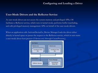
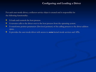
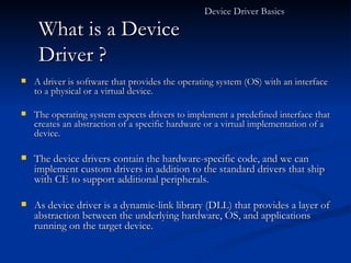
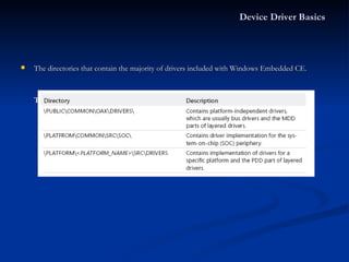
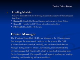
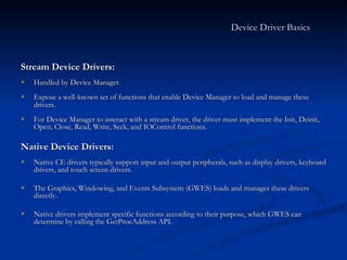
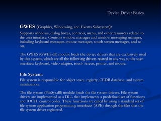
The document discusses device drivers in Windows Embedded CE 6.0, covering topics such as driver basics, implementing stream interface drivers, configuring and loading drivers, and implementing interrupt mechanisms in drivers. It provides details on driver architectures, the stream interface API, registry settings for loading drivers, and interrupt handling architecture in CE.
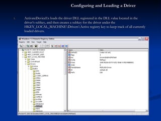
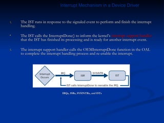
![Driver Naming Convention: The Device Manager registers the following three different file namespaces in the file system for accessing named stream drivers: Legacy: The classical naming convention for stream drivers consists of three upper case letters, a digit, and a colon. The format is XXX [0–9]:, where XXX stands for the three-letter driver name and [ 0–9 ] is the index of the driver as specified in the driver’s registry settings . For example, CreateFile(L"COM1:"…) Device - Based: A device namespace ($device) is similar to a legacy space but the former has no index restriction. format \$device\XXX[index]. For example, CreateFile(L"\$device\COM11"…) Bus - Based: This is for bus based devices as PCMCIA or USB. Format is \$bus\BUSNAME_[bus number]_[device number]_[function number] For example, CreateFile(L"\$ bus\PCMCIA_0_0_0"…). Implementing a Stream Interface Driver](https://image.slidesharecdn.com/DeviceDriverinCE6-123521324723-phpapp01/85/Device-Driver-in-WinCE-6-0-R2-27-320.jpg)