SlideShare a Scribd company logo
Revere
www.vpgtransducers.com
1
Model 9123
Technical contact in Americas: lc.usa@vishaypg.com;
Europe: lc.eur@vishaypg.com; Asia: lc.asia@vishaypg.com
Document No.: 11803
Revision: 31-Mar-2012
Single-Ended Beam Load Cell
FEATURES
•	Capacities: 500–5000 kg, 1k–20k lbs.
•	Low profile construction
•	Certified to OIML R-60, 4000d and NTEP III, 5000
divisions
•	Sealing: IP67 (DIN 40.050)
•	Stainless steel construction
•	Threaded load hole
•	Optional
❍❍ FM certified for use in potentially explosive
atmospheres
APPLICATIONS
•	Low profile platforms
•	Pallet truck weighing
•	Tank and silo weighing
DESCRIPTION
The 9123 is a low profile single-ended shear beam type
load cell. The 9123 is stainless steel.
These products are suitable for small and medium
platform scales, overhead track scales, hopper scales,
and process weighing applications.
Reliable sealing is ensured by the proprietary TRANSEAL
potting compound and additional mechanical protection
of the strain gage area.
Ease of installation is made possible through the use of
a partially threaded hole to accept levelling feet, load
buttons, or loading cables.
OUTLINE DIMENSIONS in millimeters
ØD (2x) J
F G H
A
E
6
L M
K
B
C
+ Excitation Red
– Excitation Black
+ Output Green
– Output White
Shield Transparent
Cable screen is not connected to load
cell body. Performance may be affected
if load cell cables are shortened.
Cable specifications:
Cable length: 6m
	
Capacity
Dimensions in mm Dimensions in inches
0.5T–2T 5T 1k–4k 5k–15k 20k
A 130.0 171.5 5.12 6.75 8.75
B 31.5 37.8 1.23 1.45 1.95
C 31.8 38.1 1.23 1.45 1.95
ØD 13.5 20.7 0.53 0.78 1.06
E 15.7 19.1 0.62 0.72 0.98
F 15.7 19.1 0.62 0.75 1.00
G 25.4 38.1 1.00 1.50 2.00
H 76.2 95.3 3.00 3.75 4.75
J M12x1.75-6H M20x2.5-6H ½-20UNF-2B ¾-16UNF-2B 1-12UNF-2B
K 15.7 19.1 0.62 0.75 0.98
L 57.2 76.2 2.25 3.12 4.00
ØM 13.5 20.7 0.53 0.78 1.030
Single-Ended Beam Load Cell
Document No.: 11803
Revision: 31-Mar-2012
Model 9123
Revere
www.vpgtransducers.com
2
Model 9123
Technical contact in Americas: lc.usa@vishaypg.com;
Europe: lc.eur@vishaypg.com; Asia: lc.asia@vishaypg.com
Document No.: 11803
Revision: 31-Mar-2012
Single-Ended Beam Load Cell
SPECIFICATIONS
PARAMETER VALUE UNIT
Standard capacities (Emax) 500, 1000, 2000, 5000 (1)
kg
Standard capacities (Emax) 1k, 2.5k, 4k, 5k, 10k, 15k, 20k (1)
lbs
Accuracy class according to OIML
R-60 /NTEP
NTEP III Non-Approved C3 C4
Max. no. of verfication intervals 5000 3000 4000
Min. verification interval (Vmin=Emax/Y) Emax/6000 Emax/8000
Min. verification interval, type MR Emax/10000 Emax/18000
Rated output (=S) 3 mV/V
Rated output tolerance 0.003 ±mV/V
Zero balance 1.0 ±% FSO
Combined error 0.0200 0.050 0.023 0.018 ±% FSO
Minimum dead load output return 0.0250 0.050 0.017 0.013 ±% applied load
Non-repeatability 0.0100 0.070 0.035 0.026 ±% FSO
Creep error (30 minutes) 0.060 0.025 0.018 ±% applied load
Temp. effect on min. dead load output (0.0008) 0.0250 0.0120 0.0088 ±% FSO/5°C (/°F)
Temp. effect on min. dead load output,
type MR
0.0070 0.0039 ±% FSO/5°C
Temperature effect on sensitivity (0.0010) 0.0250 0.0088 0.0065 % applied load/5°
Minimum dead load 0 % Emax
Maximum safe overload 150 % Emax
Ultimate overload 300 % Emax
Maximum safe side load 100 % Emax
Deflection at Emax
0.4 / 0.8 / 1.0 / 1.1—kg
0.4 / 0.8 / 1.0 / 0.9 / 1.1—lbs
mm
Excitation voltage 5 to 12 V
Maximum excitation voltage 15 V
Input resistance 350±3.5 Ω
Output resistance 350±3.5 Ω
Insulation resistance ≥5000 MΩ
Compensated temperature range –10 to +40 °C
Operating temperature range –40 to +80 °C
Storage temperature range –50 to +90 °C
Element material Stainless steel
Sealing (DIN 40.050 / EN60.529) IP67
Recommended torque on fixation bolts
0.5–2T and 1k–4k lbs.: 149
5k lbs. and 5T and over: 271
N*m
(1)
	 5T and 10k lbs. are not approved by OIML
FSO—Full Scale Output
Correct mounting of the load cell is essential to ensure optimum performance.
Further information is available on request.
All specifications subject to change without notice.
Vishay Precision Group, Inc.
www.vpgsensors.com
1
Legal Disclaimer Notice
Document No.: 63999
Revision: 15-Jul-2014
Disclaimer
ALL PRODUCTS, PRODUCT SPECIFICATIONS AND DATA ARE SUBJECT TO CHANGE WITHOUT NOTICE.
Vishay Precision Group, Inc., its affiliates, agents, and employees, and all persons acting on its or their behalf
(collectively, “VPG”), disclaim any and all liability for any errors, inaccuracies or incompleteness contained herein or in
any other disclosure relating to any product.
The product specifications do not expand or otherwise modify VPG’s terms and conditions of purchase, including but
not limited to, the warranty expressed therein.
VPG makes no warranty, representation or guarantee other than as set forth in the terms and conditions of purchase.
To the maximum extent permitted by applicable law, VPG disclaims (i) any and all liability arising out of the
application or use of any product, (ii) any and all liability, including without limitation special, consequential or
incidental damages, and (iii) any and all implied warranties, including warranties of fitness for particular purpose,
non-infringement and merchantability.
Information provided in datasheets and/or specifications may vary from actual results in different applications and
performance may vary over time. Statements regarding the suitability of products for certain types of applications
are based on VPG’s knowledge of typical requirements that are often placed on VPG products. It is the customer’s
responsibility to validate that a particular product with the properties described in the product specification is suitable for
use in a particular application. You should ensure you have the current version of the relevant information by contacting
VPG prior to performing installation or use of the product, such as on our website at vpgsensors.com.
No license, express, implied, or otherwise, to any intellectual property rights is granted by this document, or by any
conduct of VPG.
The products shown herein are not designed for use in life-saving or life-sustaining applications unless otherwise
expressly indicated. Customers using or selling VPG products not expressly indicated for use in such applications do
so entirely at their own risk and agree to fully indemnify VPG for any damages arising or resulting from such use or sale.
Please contact authorized VPG personnel to obtain written terms and conditions regarding products designed for such
applications.
Product names and markings noted herein may be trademarks of their respective owners.
Copyright Vishay Precision Group, Inc., 2014. All rights reserved.
Disclaimer
Legal Disclaimer Notice

More Related Content

What's hot

65016-TWA
65016-TWA65016-TWA
92-93
92-9392-93
3510
35103510
LOC
LOCLOC
65088
6508865088
65058S
65058S65058S
9303
93039303
60058
6005860058
RLC
RLCRLC
9423
94239423
60063
6006360063
60001
6000160001
60048
6004860048
ACB
ACBACB
65040W
65040W65040W
1042
10421042
5303
53035303
92001
9200192001
65114
6511465114
65023
6502365023

What's hot (20)

65016-TWA
65016-TWA65016-TWA
65016-TWA
 
92-93
92-9392-93
92-93
 
3510
35103510
3510
 
LOC
LOCLOC
LOC
 
65088
6508865088
65088
 
65058S
65058S65058S
65058S
 
9303
93039303
9303
 
60058
6005860058
60058
 
RLC
RLCRLC
RLC
 
9423
94239423
9423
 
60063
6006360063
60063
 
60001
6000160001
60001
 
60048
6004860048
60048
 
ACB
ACBACB
ACB
 
65040W
65040W65040W
65040W
 
1042
10421042
1042
 
5303
53035303
5303
 
92001
9200192001
92001
 
65114
6511465114
65114
 
65023
6502365023
65023
 

Viewers also liked

5203
52035203
BCOM
BCOMBCOM
LPS
LPSLPS
KSR
KSRKSR
SBC
SBCSBC
ASC
ASCASC
SQB
SQBSQB
KITCHEN EQUIPMENTS
KITCHEN EQUIPMENTSKITCHEN EQUIPMENTS
KITCHEN EQUIPMENTS
Eong Huat Corporation
 
IW2P1
IW2P1IW2P1
SSB MOUNT
SSB MOUNTSSB MOUNT
9102 MOUNT
9102 MOUNT9102 MOUNT
5223
52235223
RINSTRUM X320
RINSTRUM X320RINSTRUM X320
RINSTRUM X320
Eong Huat Corporation
 
RINSTRUM X320
RINSTRUM X320RINSTRUM X320
RINSTRUM X320
Eong Huat Corporation
 
HBB
HBBHBB

Viewers also liked (15)

5203
52035203
5203
 
BCOM
BCOMBCOM
BCOM
 
LPS
LPSLPS
LPS
 
KSR
KSRKSR
KSR
 
SBC
SBCSBC
SBC
 
ASC
ASCASC
ASC
 
SQB
SQBSQB
SQB
 
KITCHEN EQUIPMENTS
KITCHEN EQUIPMENTSKITCHEN EQUIPMENTS
KITCHEN EQUIPMENTS
 
IW2P1
IW2P1IW2P1
IW2P1
 
SSB MOUNT
SSB MOUNTSSB MOUNT
SSB MOUNT
 
9102 MOUNT
9102 MOUNT9102 MOUNT
9102 MOUNT
 
5223
52235223
5223
 
RINSTRUM X320
RINSTRUM X320RINSTRUM X320
RINSTRUM X320
 
RINSTRUM X320
RINSTRUM X320RINSTRUM X320
RINSTRUM X320
 
HBB
HBBHBB
HBB
 

Similar to 9123

614
614614
220
220220
CSP-M
CSP-MCSP-M
SEB
SEBSEB
9203
92039203
380
380380
9803
98039803
3310
33103310
65016
6501665016
3520
35203520
HOC
HOCHOC
1006
10061006
615 616
615 616615 616

Similar to 9123 (13)

614
614614
614
 
220
220220
220
 
CSP-M
CSP-MCSP-M
CSP-M
 
SEB
SEBSEB
SEB
 
9203
92039203
9203
 
380
380380
380
 
9803
98039803
9803
 
3310
33103310
3310
 
65016
6501665016
65016
 
3520
35203520
3520
 
HOC
HOCHOC
HOC
 
1006
10061006
1006
 
615 616
615 616615 616
615 616
 

9123

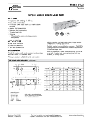
  • 1. Revere www.vpgtransducers.com 1 Model 9123 Technical contact in Americas: lc.usa@vishaypg.com; Europe: lc.eur@vishaypg.com; Asia: lc.asia@vishaypg.com Document No.: 11803 Revision: 31-Mar-2012 Single-Ended Beam Load Cell FEATURES • Capacities: 500–5000 kg, 1k–20k lbs. • Low profile construction • Certified to OIML R-60, 4000d and NTEP III, 5000 divisions • Sealing: IP67 (DIN 40.050) • Stainless steel construction • Threaded load hole • Optional ❍❍ FM certified for use in potentially explosive atmospheres APPLICATIONS • Low profile platforms • Pallet truck weighing • Tank and silo weighing DESCRIPTION The 9123 is a low profile single-ended shear beam type load cell. The 9123 is stainless steel. These products are suitable for small and medium platform scales, overhead track scales, hopper scales, and process weighing applications. Reliable sealing is ensured by the proprietary TRANSEAL potting compound and additional mechanical protection of the strain gage area. Ease of installation is made possible through the use of a partially threaded hole to accept levelling feet, load buttons, or loading cables. OUTLINE DIMENSIONS in millimeters ØD (2x) J F G H A E 6 L M K B C + Excitation Red – Excitation Black + Output Green – Output White Shield Transparent Cable screen is not connected to load cell body. Performance may be affected if load cell cables are shortened. Cable specifications: Cable length: 6m Capacity Dimensions in mm Dimensions in inches 0.5T–2T 5T 1k–4k 5k–15k 20k A 130.0 171.5 5.12 6.75 8.75 B 31.5 37.8 1.23 1.45 1.95 C 31.8 38.1 1.23 1.45 1.95 ØD 13.5 20.7 0.53 0.78 1.06 E 15.7 19.1 0.62 0.72 0.98 F 15.7 19.1 0.62 0.75 1.00 G 25.4 38.1 1.00 1.50 2.00 H 76.2 95.3 3.00 3.75 4.75 J M12x1.75-6H M20x2.5-6H ½-20UNF-2B ¾-16UNF-2B 1-12UNF-2B K 15.7 19.1 0.62 0.75 0.98 L 57.2 76.2 2.25 3.12 4.00 ØM 13.5 20.7 0.53 0.78 1.030 Single-Ended Beam Load Cell Document No.: 11803 Revision: 31-Mar-2012 Model 9123
  • 2. Revere www.vpgtransducers.com 2 Model 9123 Technical contact in Americas: lc.usa@vishaypg.com; Europe: lc.eur@vishaypg.com; Asia: lc.asia@vishaypg.com Document No.: 11803 Revision: 31-Mar-2012 Single-Ended Beam Load Cell SPECIFICATIONS PARAMETER VALUE UNIT Standard capacities (Emax) 500, 1000, 2000, 5000 (1) kg Standard capacities (Emax) 1k, 2.5k, 4k, 5k, 10k, 15k, 20k (1) lbs Accuracy class according to OIML R-60 /NTEP NTEP III Non-Approved C3 C4 Max. no. of verfication intervals 5000 3000 4000 Min. verification interval (Vmin=Emax/Y) Emax/6000 Emax/8000 Min. verification interval, type MR Emax/10000 Emax/18000 Rated output (=S) 3 mV/V Rated output tolerance 0.003 ±mV/V Zero balance 1.0 ±% FSO Combined error 0.0200 0.050 0.023 0.018 ±% FSO Minimum dead load output return 0.0250 0.050 0.017 0.013 ±% applied load Non-repeatability 0.0100 0.070 0.035 0.026 ±% FSO Creep error (30 minutes) 0.060 0.025 0.018 ±% applied load Temp. effect on min. dead load output (0.0008) 0.0250 0.0120 0.0088 ±% FSO/5°C (/°F) Temp. effect on min. dead load output, type MR 0.0070 0.0039 ±% FSO/5°C Temperature effect on sensitivity (0.0010) 0.0250 0.0088 0.0065 % applied load/5° Minimum dead load 0 % Emax Maximum safe overload 150 % Emax Ultimate overload 300 % Emax Maximum safe side load 100 % Emax Deflection at Emax 0.4 / 0.8 / 1.0 / 1.1—kg 0.4 / 0.8 / 1.0 / 0.9 / 1.1—lbs mm Excitation voltage 5 to 12 V Maximum excitation voltage 15 V Input resistance 350±3.5 Ω Output resistance 350±3.5 Ω Insulation resistance ≥5000 MΩ Compensated temperature range –10 to +40 °C Operating temperature range –40 to +80 °C Storage temperature range –50 to +90 °C Element material Stainless steel Sealing (DIN 40.050 / EN60.529) IP67 Recommended torque on fixation bolts 0.5–2T and 1k–4k lbs.: 149 5k lbs. and 5T and over: 271 N*m (1) 5T and 10k lbs. are not approved by OIML FSO—Full Scale Output Correct mounting of the load cell is essential to ensure optimum performance. Further information is available on request. All specifications subject to change without notice.
  • 3. Vishay Precision Group, Inc. www.vpgsensors.com 1 Legal Disclaimer Notice Document No.: 63999 Revision: 15-Jul-2014 Disclaimer ALL PRODUCTS, PRODUCT SPECIFICATIONS AND DATA ARE SUBJECT TO CHANGE WITHOUT NOTICE. Vishay Precision Group, Inc., its affiliates, agents, and employees, and all persons acting on its or their behalf (collectively, “VPG”), disclaim any and all liability for any errors, inaccuracies or incompleteness contained herein or in any other disclosure relating to any product. The product specifications do not expand or otherwise modify VPG’s terms and conditions of purchase, including but not limited to, the warranty expressed therein. VPG makes no warranty, representation or guarantee other than as set forth in the terms and conditions of purchase. To the maximum extent permitted by applicable law, VPG disclaims (i) any and all liability arising out of the application or use of any product, (ii) any and all liability, including without limitation special, consequential or incidental damages, and (iii) any and all implied warranties, including warranties of fitness for particular purpose, non-infringement and merchantability. Information provided in datasheets and/or specifications may vary from actual results in different applications and performance may vary over time. Statements regarding the suitability of products for certain types of applications are based on VPG’s knowledge of typical requirements that are often placed on VPG products. It is the customer’s responsibility to validate that a particular product with the properties described in the product specification is suitable for use in a particular application. You should ensure you have the current version of the relevant information by contacting VPG prior to performing installation or use of the product, such as on our website at vpgsensors.com. No license, express, implied, or otherwise, to any intellectual property rights is granted by this document, or by any conduct of VPG. The products shown herein are not designed for use in life-saving or life-sustaining applications unless otherwise expressly indicated. Customers using or selling VPG products not expressly indicated for use in such applications do so entirely at their own risk and agree to fully indemnify VPG for any damages arising or resulting from such use or sale. Please contact authorized VPG personnel to obtain written terms and conditions regarding products designed for such applications. Product names and markings noted herein may be trademarks of their respective owners. Copyright Vishay Precision Group, Inc., 2014. All rights reserved. Disclaimer Legal Disclaimer Notice