Download to read offline

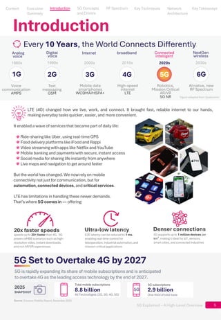

A clear, concise introduction to 5G from core concepts and architecture to spectrum and key techniques. This is a short ebook that explains, at a high level, the foundations of 5G based on 3GPP Release 15, covering: • 5G New Radio and adaptive air interface • mmWave, beamforming, and Massive MIMO • Cloud-native 5G Core and service-based architecture • Network slicing and differentiated connectivity • Mobile Edge Computing (MEC) • RAN evolution (RU / DU / CU)


